Ceco Dean Pump M300 Instruction manual

Magnetically C upled H riz ntal Pr cess Pumps
Instructi n Manual MC 1.3.10.2A DO NOT INSTALL, OPERATE, OR SERVICE THIS PUMP BEFORE READING THE ENTIRE MANUAL
DEAN PUMP® SERIES M300
6040 Gui n R ad • Indianap lis, IN 46254
(317) 293-2930 • FAX: (317) 297-7028
E-mail: inf @deanpump.c m • Web Site: www.deanpump.c m
MET-PRO
A Met-Pro Fluid Handling Technologies Business
Combining the Resources of Dean Pump, Fybroc & Sethco
Global Pump Solutions
Read the instruction manual completely, before installing, filling, operating, or maintaining this equipment.
Obtain, read, and heed the MSDS (Material Safety Data Sheet) for the fluids being handled before attempting to
fill, operate or maintain this equipment.
Obtain instructions from the Safety Engineer responsible for your facility before performing any work on the pump-
ing equipment and systems.
APPLICATION AND REAPPLICATION - At the time of installation, the equipment received should have already been
selected for the service required. You must read the paperwork for the installation and check serial number of the
pump to assure that you are installing the correct pump into the service for which it was selected.
Many pumps look identical from the outside but can be made of different materials and/or be constructed differently
inside. Personal injury, death, equipment damage, product (pumpage) damage, and/or product loss could occur if the
incorrect pump is installed.
Do not transfer an existing pump to any other service conditions until you have thoroughly reviewed the pump
construction, materials, sizing, sealing, pressure containing capability, head/capacity capability, and
temperature capability with respect to the required service. Consult your DEAN PUMP sales engineer with all the
service requirements and a full description of the existing pump (including the serial number), seal, and sub-systems
so that we can assist you in a successful reapplication.
INSTALLATION - Always wear the appropriate protective apparel when working on or around the pumping equipment.
Safety glasses with side shields, heavy work gloves (use insulated work gloves when handling hot items), steel toed
shoes, hard hat, and any other protective gear as needed for protection. One example of other gear would be
breathing apparatus when working near toxic materials.
Use lifting devices, manufactured expressly for the purpose of lifting, to move the pumping machinery. Do not attempt
to lift the assembly or its components manually. Use only devices with lifting capabilities in excess of the weight of
the unit being lifted. Inspect straps,chains, hooks, etc. for damage and lifting capability before use. Lift only at the
center of gravity.
Personal injury, death, and/or equipment damage could occur if good lifting practices are not used.
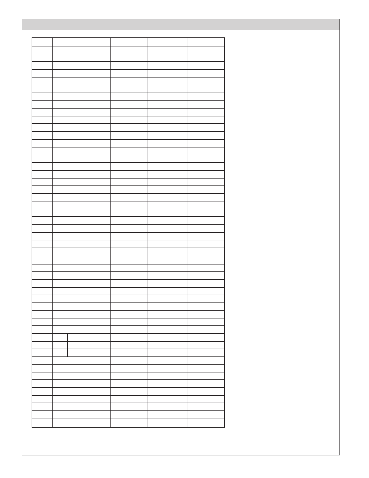
Install the equipment on a properly designed and built foundation. Assure that the driver (motor, turbine,or engine)
shaft is properly aligned to the pump shaft.
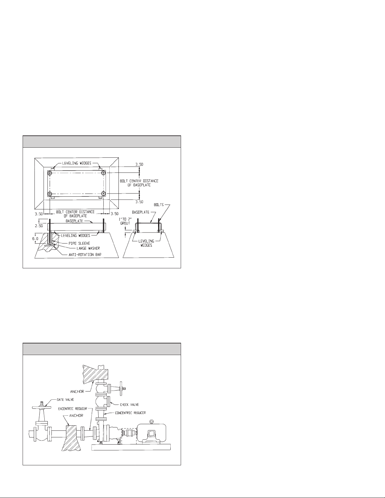
Connect the suction and discharge piping without forcing the piping into position. The pipe flanges must line up
with the pump flanges “freely”. Strain caused by “forcing” and/or misalignment may cause failure of the pumping
unit, flanges, and/or the piping resulting in fluid (pumpage) release. This could cause personal injury, death and/or
damage to this and/or other equipment.
Install a “new” bolt, of the correct size per ASME/ANSI B16.5 and the correct material per ASME/ANSI B16.5,
in every bolt hole. Tighten all bolts evenly. Use only new uncorroded fasteners.
Improper flange bolting may cause failure of the pumping unit, flanges, piping, and/or fluid (pumpage) release
which could cause personal injury, death, and/or damage to this and/or other equipment.
Connect all other (auxiliary) piping necessary for safe and successful operation of the equipment in the specific ser-
vice conditions of the application. Make sure that all piping is installed into it’s correct connection. Installation of a
pipe into an incorrect location could result in an explosion and personal injury or death as well as damage to this
and/or other equipment.
Install pressure relief valves in any cavities that could be subjected to pressures in excess of the allowable working
pressure of that cavity. Explosion, personal injury, death, and/or damage to this and/or other equipment may occur
if pressure exceeds allowable.
Recheck the alignment between the driver (motor, turbine, or engine) and pump shafts. Installation of piping may have
forced the pump out of alignment. If so, correct the piping to remove the distorting load.
Check to be certain that the shaft coupling spacer is not installed, and then gently bump the motor starter to check
the rotational direction of the motor. If this is not in the direction of rotation required for the pump, make the neces-
sary corrections.
Lock-out the power to the driver (motor, turbine, engine, etc.)
Install the shaft coupling spacer. Be sure that you install all the retaining devices and bolts and that they are tight.
Read and comply with the coupling manufacturer’s instructions. Personal injury, death, and/or equipment damage
could occur if the coupling spacer is not properly installed. Remove all debris and tools from the area near the shafts
and the shaft coupling. Do this to assure that nothing is caught and thrown by the rotating parts when the pump is
started. Bolt the coupling guard securely to the baseplate, checking to assure that it is not contacting any parts that
will rotate when the pump is started.
FILLING - Before filling the pump with liquid, check to see that all possible leak locations are sealed. See that all of
the connections into the pressure containing cavity are sealed or connected to a related piping system that also has
all possible leak paths sealed. Do not plug unused jacket cavities, as this could develop dangerous pressure build-
up. Use a wrench on all bolted joints to apply torque to assure that all gaskets are sealed in a tight joint. Check to
see that all threaded pipe connections are also tight enough to seal the liquid pressure that will be applied when
the system is started.
OPERATING - Before starting the unit, see that all personnel are a safe distance away from all possible hazards,
that all sub-systems are connected and operating, that all debris has been removed, that the shaft coupling guard
is securely in place, and that the pump is full of liquid.
Do not operate this pump at shut-off (no flow) as an explosion may result. This can occur with any liquid, even “cold
water”. Personal injury, death, equipment damage, and/or loss of product (pumpage) is likely to occur. If your sys-
tem is operated where it is possible for all outlets for the discharge from the pump to be closed while the pump is
still operating, a modification of the system needs to be made to assure a continual flow of pumpage through the
pump. Note that some people have a belief that a bypass line from the discharge side of the pump to the suction
side of the pump will relieve this problem, this is “NOT TRUE”; DO NOT ATTEMPT THIS.
MAINTENANCE, DISASSEMBLY AND REPAIR - Work must be performed only by thoroughly trained and qualified
personnel to assure quality repair and to reduce the possibilities of injury to personnel and/or damage to equip-
ment. If you do not have personnel who are capable of safe quality repair of this equipment, we advise you to return
the equipment to DEAN PUMP to be repaired.
When it is necessary to open the pump and/or the pumping system, the fluid will be exposed to the atmosphere
and personnel in the area. For the safety of all involved, the risk of exposure of personnel to the hazards of the
pumpage can be reduced by flushing the entire system with a compatible non-toxic, non-hazardous,stable liquid
before opening the pump or the system. In all cases, where the system is flushed or not, use the utmost care around
the pumpage and the pumping system.
Always wear the appropriate protective apparel when working on or around the pumping equipment. Safety glass-
es with side shields, heavy work gloves (use insulated work gloves when handling hot items), steel-toed shoes, hard
hat, and any other protective gear as needed for protection. One example of other gear would be breathing
apparatus when working near toxic materials.
Use only top quality tools.
Stop the pump. Turn off the power supply (electricity, steam, etc.) to the pump driver (motor, turbine, engine, etc.)
and lock the switching device so that it cannot be restarted. Tag the switching device so that no one will attempt to
restart the unit.
Close the suction and discharge valves completely to isolate the pump from the system. Lock the valves in the closed
position and tag them so that no one will attempt to open them.
Turn off, lock out, and tag all sub-systems and auxiliary equipment and auxiliary supply lines to isolate the pump-
ing unit from any and all power, energy, and/or fluids.
Do not attempt to perform any work on the unit until you are confident that the pump and its contents have been
stabilized at ambient temperature, and atmospheric pressure.
Put on protective wear to protect human tissue from attack by the fluids contained in the pump and any sub-systems,
and from any vapors or fumes that could possibly be released from these fluids. This could mean breathing apparatus,
face shields, heavy long sleeve rubber gloves, rubber apron, hood, and possibly more, dependent of course on the
properties of the fluids involved and the installed drain and vent piping arrangement. Personal injury and/or death
can occur if adequate precautions are not taken with regard to the fluid, the installation, and the possibilities of the
release of fluid, vapors, and/or fumes.
Remove the coupling guard. Remove the coupling spacer.
Drain all the fluids from the auxiliary sub-systems (lubrication, cooling, heating, seal barrier, etc.) that are connect-
ed to the pump. Drain each fluid into a separate container. Use caution required for each fluid after reading the
MSDS (Material Safety Data Sheet) for each.
Flush each sub-system with a compatible, non-toxic, non-hazardous, stable liquid. Drain into individual containers
for each fluid. Disconnect and remove all auxiliary piping.
Carefully bleed off any pressure remaining in the pump. Pressure remaining in the pump will be dependent upon
the pressure in the system when the pump was stopped; the quality, type, and condition of the isolation valves; the
thermal expansion valves of the fluid and the pump material; and the change in the vapor pressure of the fluid
between the temperature at the time the isolation valves were closed and the ambient temperature. Bleeding must
be through a valved drain line piped to a closed container mounted lower than the pump. The container must be
arranged with a relief passage to some point where pressure and fumes will not be harmful to personnel. The
container must also have a level device so that determination can be made that sufficient fluid has been drained to
empty the pump cavity and the volume of fluid that was contained in the run of suction and discharge pipe between
the isolation valves and the pump. After the initial rush of fluid from the pump relieves the pressure, the drain valve
can be opened further to speed the draining operation. When fluid quits running into the drain tank, gauge the
volume to see if it is sufficient to have fully drained the contents of the pump and the suction and discharge pipes
between the isolation valves.
If the system was constructed without any drain connections, it will be necessary to consult the designers of the system
for safe draining procedures.
Now drain any small piping, that contains the fluid pumped, from all low points, into the same container used to drain
the pump. Do not drain any other fluids (different than the pumpage) into this container as they may not be
compatible. Personal injury, death, and/or equipment damage could occur.
Even though it might appear that, the cavity being drained has completely drained, be extremely careful about
opening the system and/or opening the pump. If something solid in the pumpage moves to the vicinity of the drain
connection, it could seal-off the drain and maintain pressure in the cavity thought to have been drained. It is also
possible that the isolation valves are not sealing and therefore allowing liquid to flow from the system into the pump.
Personal injury, death, and/or equipment damage may occur if intense caution is not exercised.
Because of the above possibility, when you loosen the gasketed joint at the back of the casing (5), loosen the bolts or
nuts only one full turn, and then use jack screws to break the gasket seal. If fluid and/or pressure remains in the pump,
it will spray out now. Use extreme caution, wearing protective gear, to avoid injury. Do not proceed with disas-
sembly until leakage ceases completely. If leakage does not cease, the isolation valves may not be sealing. Note
that if the pump was purchased with out a drain, the pump will contain fluid which will flow out at the time the bolts
are loosened and the gasket seal is broken.
When you open the pump, the fluid will be exposed to the atmosphere and personnel in the area. For the safety of
all involved, the risk of exposure can be reduced by flushing the cavity that was just drained, with a compatible non-
toxic, non-hazardous, stable liquid, before disassembling the pump.
Remove the casing bolts or nuts and using mechanical lifting apparatus to support the weight, pull the rotating unit
from the casing.
Flush the wetted parts now exposed with compatible, non-toxic, non-hazardous, stable liquid.
Remove the gasket from the face of the casing (5) or the bearing housing (26) dependent on which one the gasket may
have adhered to. The type of gasket and material of construction will vary with service requirements. Attack by prying
and then, if necessary, layering off the old gasket with a sharp scraper, attempting to remove it in the largest possible
pieces. Wear heavy leather, long sleeve work gloves when using the scraper. Wet the gasket before and during the
scraping operation to reduce the possibility of fibers becoming airborne. Wear a respirator during this operation and
until all debris has been disposed of in a plastic bag. Remove all of the gasket material down to clean metal surfaces
on both parts that contacted the gasket. Place all of the gasket residue in a plastic bag, seal the bag and dispose of it
in compliance with all government requirements.
The rotating assembly of the pump can now be moved to a more convenient location for further disassembly. Use
only high quality tools. Flush parts as disassembled to removed hazardous residue from the pumpage and/or
sub-system fluids.
Wear protective equipment as advised at the beginning of these warnings.
Use mechanical lifting equipment to lift assemblies and components.
Do not apply heat to parts to assist in disassembly. Explosion could occur causing personal injury, death, and/or
damage to equipment.
Do not attempt to drill, saw, or otherwise cut parts to remove them. Explosion and/or fuming could occur causing
personal injury, death, and/or equipment damage.
Do not hammer on any parts. Personal injury and/or damage to equipment may occur.
Do not attempt to manufacture parts or modify Dean Pump parts in any manner. Death, personal injury, and/or
damage to equipment may occur.
One example of the above would be overboring the seal chamber, which removes metal that is required to contain
fluids. Removal of this metal reduces the pressure containing capability of the part, and may create a leak path
through the part.
Replace all gaskets, seals, bearings, and lubricants. Replace all parts that have worn, corroded, eroded, or other-
wise deteriorated.
Use only Dean Pump Met-Pro Corporation parts.
HAZARDOUS SITUATIONS MAY OCCUR UNLESS THIS EQUIPMENT IS APPLIED, INSTALLED, OPERATED, AND MAINTAINED BY THOROUGHLY QUALIFIED PERSONNEL
IN STRICT ACCORDANCE WITH THE INSTRUCTION MANUAL AND ALL APPLICABLE DRAWINGS AND CODES.
READ WARNINGS
©COPYRIGHT 2012 MET-PRO CORPORATION, DEAN PUMP DEAN PUMP ®IS A REGISTERED TRADEMARK OF MET-PRO CORPORATION. 09-5908 512

INDEX
Caution . . . . . . . . . . . . . . . . . . . . . . . . . . . . . . . . . . . . . . . . . . . . . . . . . . . . . . . . . . . . . . . . . . . . . . . . . . . . . . . . . . . . . .3
Product Inspection and Test . . . . . . . . . . . . . . . . . . . . . . . . . . . . . . . . . . . . . . . . . . . . . . . . . . . . . . . . . . . . . . . . . . . . .3
Product Warranty . . . . . . . . . . . . . . . . . . . . . . . . . . . . . . . . . . . . . . . . . . . . . . . . . . . . . . . . . . . . . . . . . . . . . . . . . . .3
Warning . . . . . . . . . . . . . . . . . . . . . . . . . . . . . . . . . . . . . . . . . . . . . . . . . . . . . . . . . . . . . . . . . . . . . . . . . . . . . . . . . . . .4
Receiving Pump . . . . . . . . . . . . . . . . . . . . . . . . . . . . . . . . . . . . . . . . . . . . . . . . . . . . . . . . . . . . . . . . . . . . . . . . . . . .4
Storage . . . . . . . . . . . . . . . . . . . . . . . . . . . . . . . . . . . . . . . . . . . . . . . . . . . . . . . . . . . . . . . . . . . . . . . . . . . . . . . . . .4
Mechanical Design Specifications . . . . . . . . . . . . . . . . . . . . . . . . . . . . . . . . . . . . . . . . . . . . . . . . . . . . . . . . . . . . . . . . . . .5
Standard Materials of Construction . . . . . . . . . . . . . . . . . . . . . . . . . . . . . . . . . . . . . . . . . . . . . . . . . . . . . . . . . . . . . . . . . .6
Pressure/Temperature . . . . . . . . . . . . . . . . . . . . . . . . . . . . . . . . . . . . . . . . . . . . . . . . . . . . . . . . . . . . . . . . . . . . . . . . . . .7
Installation . . . . . . . . . . . . . . . . . . . . . . . . . . . . . . . . . . . . . . . . . . . . . . . . . . . . . . . . . . . . . . . . . . . . . . . . . . . . . . . . . . .8
Pump Foundation . . . . . . . . . . . . . . . . . . . . . . . . . . . . . . . . . . . . . . . . . . . . . . . . . . . . . . . . . . . . . . . . . . . . . . . . . . .8
Suction and Discharge Piping . . . . . . . . . . . . . . . . . . . . . . . . . . . . . . . . . . . . . . . . . . . . . . . . . . . . . . . . . . . . . . . . . . .8
Baseplate Mounting and Alignment . . . . . . . . . . . . . . . . . . . . . . . . . . . . . . . . . . . . . . . . . . . . . . . . . . . . . . . . . . . . . . .9
Pump and Driver Alignment . . . . . . . . . . . . . . . . . . . . . . . . . . . . . . . . . . . . . . . . . . . . . . . . . . . . . . . . . . . . . . . . . . . .9
Grouting the Baseplate . . . . . . . . . . . . . . . . . . . . . . . . . . . . . . . . . . . . . . . . . . . . . . . . . . . . . . . . . . . . . . . . . . . . . .10
Allowable Piping Loads . . . . . . . . . . . . . . . . . . . . . . . . . . . . . . . . . . . . . . . . . . . . . . . . . . . . . . . . . . . . . . . . . . . . . . . . .11
Piping Connections . . . . . . . . . . . . . . . . . . . . . . . . . . . . . . . . . . . . . . . . . . . . . . . . . . . . . . . . . . . . . . . . . . . . . . . . . . . .12
Internal . . . . . . . . . . . . . . . . . . . . . . . . . . . . . . . . . . . . . . . . . . . . . . . . . . . . . . . . . . . . . . . . . . . . . . . . . . . . . . . . . .12
External . . . . . . . . . . . . . . . . . . . . . . . . . . . . . . . . . . . . . . . . . . . . . . . . . . . . . . . . . . . . . . . . . . . . . . . . . . . . . . . . .13
Optional Protection Systems . . . . . . . . . . . . . . . . . . . . . . . . . . . . . . . . . . . . . . . . . . . . . . . . . . . . . . . . . . . . . . . . . . . . . .14
Temperature Probe . . . . . . . . . . . . . . . . . . . . . . . . . . . . . . . . . . . . . . . . . . . . . . . . . . . . . . . . . . . . . . . . . . . . . . . . . .14
Electrical Power . . . . . . . . . . . . . . . . . . . . . . . . . . . . . . . . . . . . . . . . . . . . . . . . . . . . . . . . . . . . . . . . . . . . . . . . . . . .14
Vibration . . . . . . . . . . . . . . . . . . . . . . . . . . . . . . . . . . . . . . . . . . . . . . . . . . . . . . . . . . . . . . . . . . . . . . . . . . . . . . . . .14
Pressure Switch . . . . . . . . . . . . . . . . . . . . . . . . . . . . . . . . . . . . . . . . . . . . . . . . . . . . . . . . . . . . . . . . . . . . . . . . . . . .14
Level Switch . . . . . . . . . . . . . . . . . . . . . . . . . . . . . . . . . . . . . . . . . . . . . . . . . . . . . . . . . . . . . . . . . . . . . . . . . . . . . .14
Secondary Containment Seal . . . . . . . . . . . . . . . . . . . . . . . . . . . . . . . . . . . . . . . . . . . . . . . . . . . . . . . . . . . . . . . . . .14
Pump Lubrication . . . . . . . . . . . . . . . . . . . . . . . . . . . . . . . . . . . . . . . . . . . . . . . . . . . . . . . . . . . . . . . . . . . . . . . . . . . . . .14
Starting the Pump . . . . . . . . . . . . . . . . . . . . . . . . . . . . . . . . . . . . . . . . . . . . . . . . . . . . . . . . . . . . . . . . . . . . . . . . . . . . .15
Pump Start-Up Checklist . . . . . . . . . . . . . . . . . . . . . . . . . . . . . . . . . . . . . . . . . . . . . . . . . . . . . . . . . . . . . . . . . . . . . . . . .16
Spare Parts . . . . . . . . . . . . . . . . . . . . . . . . . . . . . . . . . . . . . . . . . . . . . . . . . . . . . . . . . . . . . . . . . . . . . . . . . . . . . . . . . .17
Ordering Spare Parts . . . . . . . . . . . . . . . . . . . . . . . . . . . . . . . . . . . . . . . . . . . . . . . . . . . . . . . . . . . . . . . . . . . . . . . .17
Secondary Containment Seal Section . . . . . . . . . . . . . . . . . . . . . . . . . . . . . . . . . . . . . . . . . . . . . . . . . . . . . . . . . . . . . . .17
Pump Section View . . . . . . . . . . . . . . . . . . . . . . . . . . . . . . . . . . . . . . . . . . . . . . . . . . . . . . . . . . . . . . . . . . . . . . . . . . . .18
Parts List . . . . . . . . . . . . . . . . . . . . . . . . . . . . . . . . . . . . . . . . . . . . . . . . . . . . . . . . . . . . . . . . . . . . . . . . . . . . . . . . .18
Internal Circulation Flow Path . . . . . . . . . . . . . . . . . . . . . . . . . . . . . . . . . . . . . . . . . . . . . . . . . . . . . . . . . . . . . . . . . . . . .19
Disassembly and Assembly Procedures . . . . . . . . . . . . . . . . . . . . . . . . . . . . . . . . . . . . . . . . . . . . . . . . . . . . . . . . . . . . . .20
Dean Pump Serial Number
Plant Property Number
Service
Location
Capacity ; T.D.H. ; Imp. Dia. ; Temp. ; RPM
Spare Parts in Plant Stock Room
Interchangeable with Dean Serial Numbers
CUSTOMER’SPLANT MAINTENANCE RECORD
2 27

26 3
w) Lay the assembly over so that the shaft is in a horizontal
position.
x) Remove the impeller nut (12), impeller washer (12A)
and the handle, or the optional eye bolt.
y) Lubricate the unslotted face of a new thrust collar (210)
with a light oil and place it over the exposed end of the
journal sleeve (200), so that the lubricated face mates
against the face of the bearing bushing (182). Place the
impeller key (4) into the keyway of the pump shaft (29),
being sure that it engages the slot in the end of the
journal sleeve (200). Drive the thrust collar dowel
(210A) into the impeller (3). Slide the impeller (3) onto
the pump shaft (29), being careful to have the thrust
collar (210) rotated to such a position that its dowel
hole receives the thrust collar dowel (210A). Place the
impeller washer (12A) over the end of the pump shaft
(29) and against the impeller (3). Place the impeller
spring washer (12B) over the end of the pump shaft
(29) so that its concave (dished) side rests against the
impeller washer (12A). Install and tighten the impeller
nut (12) to 30 ft. lb. (for Frames I and II) or 60 ft. lb.
(for Frame III) while holding the impeller (3) against
rotation with a piece of bar stock placed between the
impeller blades (3). It is important to restrain the
impeller (3) from rotation in this manner to reduce the
possibility of breaking the internal silicon carbide parts.
Apply two drops of Locite “Thread Lock” #222 to the
threads of a new locking set screw (12D) and thread it
into the impeller nut (12). Tighten the locking set screw
(12D) to 15 Ft. Lb., while holding the impeller (3)
against rotation as described above.
z) Press a new casing wear ring assembly (190) into
the casing (5) with the stepped side of the assembly
facing out.
CAUTION: Wear safety glasses, gloves, and a long
sleeved shirt during this operation. Care must be
exercised so that the brittle inner member of the
casing wear ring assembly (190) is not broken.
aa) Install any auxiliary piping which must be affixed to the
pump before it is mounted to the baseplate.
ab) Place a new casing gasket (77) into the casing (5) and
then carefully slide the rotating assembly into the casing
and tighten the casing bolts, slowly and evenly to 50 Ft. Lb.
ac) Rotate the drive shaft (29A) by hand to check for any
internal interference. Correct as required.
ad) Bolt the pump to the baseplate, install the coupling hubs,
realign the pump and driver; refer to “PUMP AND
DRIVER ALIGNMENT.”
ae) Check the motor rotation, install the coupling spacer
and the coupling guard.
af) Install any remaining auxiliary piping. Close any drain
valves or open connections in the auxiliary piping.
ag) Fill, lubricate, and vent the pump per the sections titled,
“PUMP LUBRICATION” and “STARTING THE PUMP.”
ah) Follow instructions under “PUMP START-UP CHECK LIST.”
CAUTION—THIS EQUIPMENT CONTAINS BRITTLE AND
MAGNETIC MATERIALS.
CAUTION—EXTREME HAZARD
HEART Magnets in/from this pump can upset the timing of
heart pacemakers and make them malfunction. This caution
cannot be overstated due to the health risk involved.
EYES, HANDS, FINGERS, EXPOSED FLESH Brittle materials
(such as silicon carbide and carbon used for wearing parts)
can fracture and propel hard, sharp particles causing serious
personal injury. Protective equipment must be utilized when
servicing these parts.
The magnets are also very brittle and if cracked or fractured
can propel hard, sharp particles causing serious personal
injury. Protective equipment must be utilized when servicing
these parts.
The magnets used in this pump are very strong and can cause
parts and tools to slam together injuring hands and fingers.
This could also crack the magnets and propel particles as
cautioned above.
WARNING—EQUIPMENT DAMAGE
Some equipment, instruments, and personal possessions could
be damaged and/or destroyed. For example, computers,
computer tapes, computer discs, credit cards and any other
magnetically actuated devices will be rendered useless if
exposed to the strong magnetic field of this pump or its parts.
Watches, spring driven or electronic, will be ruined if exposed
to the strong magnetic field of this pump or its parts.
WARNING—FREIGHT
When shipping raw or bare magnet assemblies, especially by
air, special precautions may be necessary. Usually the shipment
of an assembled pump is not a problem. Consultation with
Dean Pump and the freight company is recommended.
This pump is designed incorporating a relatively new concept
called a “Magnetic Coupling”, and many mechanics will not
have the experience to realize the potential hazard of the
energy stored in the very powerful magnets.
The magnets are installed in two different parts of the pump;
the outer magnet assembly (167), which is driven by the driver
(electric motor), and the inner magnet assembly (175), which is
driven through its magnetic attraction with the outer magnet
assembly (167). There is little magnetic field outside the confines
of the pump components when they are in a completely
assembled pump.
When the pump is partially or completely disassembled, how-
ever, there is a very strong magnetic field, which, if mishandled,
could cause personal injury and/or mechanical damage.
Pinched fingers and hands are the most common personal
injury when any ferrous part comes close to a magnetic field.
This hazard also exists when holding parts with your hands
during assembly.
The most common mechanical damage is chipped magnets and
ruined wrist watches. Chipped magnets, if used, can cause
extensive mechanical damage when particles come loose during
operation. Wrist watches stop dead when they are exposed to
the magnetic field. Non-magnetic tools should be used when
working on, or in close proximity to, magnetic assemblies.
Cleanliness of the magnetic parts is very important as it is
difficult to remove ferrous particles which are “stuck” to the
magnets. Magnetic parts should be sealed in plastic bags and
stored away from the presence of ferrous articles and particles.
The magnetic coupling in each individual pump is selected for
that particular service and is mated with the motor size (power
and inertia) and coupling size. It is critical that maximum and
minimum values of operating condition are known; particularly
temperature, vapor pressure, specific gravity, and viscosity. Any
change in operating conditions which affects specific gravity,
viscosity, differential head, temperature, specific heat, capacity
or speed, may cause the couplings to dis-engage. Change of
motor or coupling could cause the same problem.
If any of the above changes are desired, contact Dean Pump
with all the changes in conditions and we will recalculate the
unit to see if it is acceptable or, if not, what modifications might
be possible.
PRODUCT INSPECTION AND TEST
The Products of Dean Pump Division are subject to thorough
and rigorous quality control and inspection procedures through-
out the whole of the manufacturing process to assure proper
operation in full conformity with established performance
standards. On completion of inspection, each unit is sprayed
internally with rust inhibitor (if material is subject to atmospheric
corrosion), sealed against the entrance of dirt, and tagged with
a signed certificate of inspection prior to shipment. Each pump
when shipped is ready to perform the service for which it was
designed with minimum maintenance and expense if properly
installed and operated in accordance with the instructions
furnished.
DEAN PRODUCT WARRANTY
We warrant to the purchaser from us of Dean Pump products
and parts of our own manufacture (Dean Products) that the
Dean Products are free “under rated use and service” from
defects in design, material and workmanship for a period of
one (1) year from the date of installation, but not to exceed
eighteen (18) months from the date of shipment by us. This
warranty does not cover (I) any loss or damage resulting from
wear, corrosion, abrasion or deterioration due to normal use in
rated service; (II) replacement of service items such as lip seals,
and mechanical seals; (III) products or parts manufactured by
others but furnished by us which, if defective, shall be repaired
or replaced only to the extent of the original manufacturer‘s
CAUTION

4 25
safety glasses, gloves, and a long sleeved shirt during
this operation. Care must be exercised so that the brittle
inner member of the casing cover wear ring assembly
(195) is not broken. Drive the clamp ring dowel (149A)
into the casing cover (22).
l) Slide a new bearing cartridge (180) into the casing cover
(22) and rotate it until the four bolt holes line up with the
four tapped holes in the casing cover (22). The four holes
are unequally spaced so that the bearing cartridge (180)
will be in correct orientation with the casing cover (22). Be
sure the tapped holes and the cap screws are clean. Apply
two drops of Loctite “Thread Lock” #222 to the threads of
each of the cap screws (180A) and secure the bearing
cartridge (180) to the casing cover (22). Tighten the bearing
housing screws (180A) to 15 Ft. Lb. on Frames I & II which
have 5/16” screws, or 35 Ft. Lb. on Frame III which has
7/16” screws.
m) Be sure that the pump shaft (29) is clean. Snap new
tolerance rings (200B) into the two grooves in the pump
shaft (29) closest to the larger end of the pump shaft (29).
Rotate the tolerance rings (200B) so that their joints are 180
degrees apart. Press a new journal sleeve (200), slotted end
first, onto the pump shaft (29), against the shaft shoulder,
being careful to align the slot in the journal sleeve (200)
with the keyway in the pump shaft (29). Handle the journal
sleeves (200) very carefully as they are very brittle and
therefore will break easily.
Place a new sleeve gasket (77H), the bearing spacer
(17) and a second sleeve gasket (77H) over the pump
shaft (29). Install two new tolerance rings (200B) into the
remaining grooves in the pump shaft (29). Rotate the
tolerance rings (200B) so that their joints are 180
degrees apart. Press a new journal sleeve (200), slotted
end last, onto the pump shaft (29) being careful to align
the slot in the journal sleeve (200) with the keyway in the
pump shaft (29).
n) CAUTION: The inner magnet assembly (175) contains
powerful magnets. Be sure that the inner magnet
assembly (175) is clean. Ferrous particles attracted to
the magnets are very difficult to remove. A piece of
masking tape drawn “sticky side” across the surface of
the inner magnet assembly (175) will help remove parti-
cles. Place the inner rotor key (171A) into the keyway
in the pump shaft (29), being sure that it engages the
slot in the journal sleeve (200). Apply four drops of
Loctite “Thread Lock” #222 to the diameter of the pump
shaft (29) which engages the inner magnet assembly
(171). Carefully slide the pump shaft (29) into the inner
magnet assembly (175) until the shoulder of the pump
shaft (29) seats firmly against the face of the counter-
bore in the inner magnet assembly (175); a light press
may be required. Set this assembly aside, with the shaft
horizontal, until the Loctite dries.
o) Carefully place a new thrust collar (210), slotted end first,
over the pump shaft (29) and into the inner magnet
assembly (175) positioning the slot to engage the inner
rotor key (171A).
p) Lubricate the bearings (182), the journal sleeves (200)
and the face of the thrust collar (210) with a light oil.
Slide the pump shaft (29) carefully through the bearings
(182) in the bearing cartridge (180). It is most important
when assembling these parts to assure that the thrust
collar (210) does not move away from its seating face
in the inner magnet assembly (175); therefore, in all
handling of this assembly be sure that the impeller (3)
end of the pump shaft (29) is always kept higher than
the inner magnet assembly (175) end.
q) Place the handle, described in paragraph b of the
Disassembly Procedures, over the end of the pump shaft
(29) and clamp it into place with the impeller washer
(12A) and the impeller nut (12), or use the optional
eye bolt.
r) Place a new containment shell gasket (77G) into the
groove in the casing cover (22). Place the containment
shell (150) into position over the bearing cartridge
(180) and place the clamping ring (149) into position,
engaging the dowel pin in the casing cover (22). Apply
two drops of Loctite “Thread Lock” #222 to the threads
of each of the cap screws (149B) and tighten them to
20 Ft. Lb. on Frames I & II which have 3/8” screws, or
35 Ft. Lb. on Frame III which has 7/16” screws, to
secure the clamping ring (149) to the casing cover (22).
s) If the pump is equipped with an optional “Secondary
Containment Seal”, place a new frame gasket (77K) into
the O-ring groove in the casing cover (22).
t) Remove the 1/8" thick rubber protective pad, as
described in paragraph g), from the inside of the outer
magnet assembly (167). Clean both the outer magnet
assembly (167) and the containment shell (150) of any
particles which might have been attracted to them, to
prevent damage to the magnets during operation.
Ferrous particles which stick to the magnet surfaces can
be removed by using a piece of masking tape rubbed
“sticky side” across the magnet surfaces.
u) CAUTION: Strong magnetic field, parts must be mechanically
restrained to prevent injury or damage.
Stand the frame (26) assembly up vertically on the end of
the drive shaft (29A) and have one man hold it in position
while a second man, using a small hoist, hooked to the
handle or eyebolt described in paragraph q, carefully low-
ers the inner magnet assembly (175) into the outer magnet
assembly (167). CAUTION: The outer magnet assembly
(167) will strongly attract the inner magnet assembly (175)
when the magnetic fields approach each other, snapping the
parts together rapidly. Fingers attempting to hold the parts
during this assembly could be severely damaged. The
containment shell (150) must also be carefully centered as it
is lowered into the outer magnet assembly (167) so that it
does not strike and damage the magnets.
v) Rotate the casing cover (22) until the two tapped holes
line up with the drilled holes in the frame (26). These
holes are unequally spaced so that the parts will locate in
only one position. Install and tighten the two cap screws.
warranty; (IV) any loss or damage to or defects in any Dean
Products resulting from the misuse or improper storage, installa-
tion, or operation thereof; or (V) any loss or damages to or
defects in any Dean Products resulting from any alteration or
modification thereof not expressly authorized and approved by
us in writing. We shall not be liable, directly or indirectly,
under any circumstances for consequential or incidental dam-
ages, including, but not limited, to (I) any loss of business or
profits; and (II) labor, material or other charges, claims, losses
or damages incurred or suffered from, in connection with or in
consequence of the working upon, alteration, or repair of any
defective Dean Products by persons or firms other than us. Our
liability for breach of warranty hereunder is limited solely to
the repair in our factory or the replacement F.O.B. our factory,
as the case may be, of any Dean Products which shall have
been determined by us, after notice to us and inspection by us
within the warranty period, to be so defective when shipped
by us.
THIS WARRANTY AND THE LIABILITY SET FORTH HEREIN ARE
EXCLUSIVE AND IN LIEU OF ALL OTHER LIABILITIES AND
WARRANTIES, EXPRESS OR IMPLIED, INCLUDING IMPLIED
WARRANTIES OF MERCHANTABILITY AND FITNESS FOR
PARTICULAR PURPOSE.
WARNING
Proper storage while not in use and proper installation and
start-up are essential for successful pump operation. Misuse or
improper storage, installation or operation of pumps may result
in serious loss or damage. Dean Pump Division is not responsi-
ble for any loss or damage resulting from causes beyond its
control, and is not liable for charges for work performed or
materials furnished to repair such loss or damage.
ALL INSTALLATION, OPERATION, AND MAINTENANCE
MUST BE DONE BY THOROUGHLY QUALIFIED PERSONNEL
IN STRICT ACCORDANCE WITH THIS MANUAL AND MUST
COMPLY WITH ALL LOCAL, STATE AND FEDERAL CODES.
ONLY DEAN AUTHORIZED SERVICE PARTS SHOULD BE USED
IN THE REPAIR OF THESE PUMPS.
RECEIVING PUMP
When the pump is received from the transportation company, it
should be promptly inspected for damage and such damage
noted on the bill of lading before it is signed. Claims for ship-
ping damage must be filed against the carrier.
Care should be exercised in unloading and handling the pump.
Magnetically coupled pumps quite often contain brittle compo-
nents which can be broken by the shock of mishandling or
dropping of the unit.
STORAGE
Pumps must be properly covered and protected against mois-
ture, dirt, and physical damage during storage prior to installa-
tion. If prolonged storage is anticipated, a heavy protective
coating should be applied to all exposed machined surfaces. A
rust preventative must be used to protect all steel or cast iron
parts. The pump shaft and the motor shaft must be rotated by
hand every three months.
Pumps must also be protected from moisture, dirt, and physical
damage during and after installation while the system is being
completed. Pumps “stored” on their foundations must be com-
pletely checked for proper installation prior to start-up.
Care in storage and installation will preserve the built in
quality of each Dean Product.

MECHANICAL DESIGN SPECIFICATIONS
Frame I Frame II Frame III
Direction of Rotation CW CW CW
(viewed from coupling end)
Corrosion Allowance Casing 0.125” 0.125” 0.125”
Shell (.047” min wall thickness) .010” (Hastelloy C) .010” (Hastelloy C) .010” (Hastelloy C)
Impeller Balance: Standard Single Plane Dynamic Balance
Magnet Assembly Balance: Standard
Double Plane Dynamic Balance
Flanges
ANSI Class 150 150 150
Facing: Standard F. F. F. F. F. F.
Optional R. F. R. F. R. F.
Finish 125 Ra 125 Ra 125 Ra
Outer Bearings (Ball)
Radial 6210 2 RS 6012 2 RS 6012 2 RS
Thrust 6305NR 2 RS 6307NR 2 RS 6307NR 2 RS
Lubrication Grease Lube for Life Grease Lube for Life Grease Lube for Life
Internal Bearings Silicon Carbide vs. Silicon Carbide vs. Silicon Carbide vs.
Silicon Carbide Silicon Carbide Silicon Carbide
Magnets Samarium Cobalt Samarium Cobalt Samarium Cobalt
Hydrostatic Test Pressure 430 psig 430 psig 430 psig
Minimum Operating Temp. 0˚F 0˚F 0˚F
Maximum Operating Temp. ⁄350˚F 350˚F 350˚F
Maximum Working Pressure⁄
@ 100˚F
Minimum Viscosity 0.3 Cp. 0.3 Cp. 0.3 Cp.
Maximum Viscosity 300 Cp. 300 Cp. 300 Cp.
Maximum Solids Size 100 Micron 100 Micron 100 Micron
Maximum Solids Content 1.5% 1.5% 1.5%
Pump Shaft Dimensions:
Diameter at Coupling 0.875” 1.125” 1.125”
Diameter at Impeller 0.750” .750” 1.250”
Minimum Pump Shaft End Play
0.009” 0.009” 0.009”
Maximum Pump Shaft End Play 0.030” 0.030” 0.030”
Maximum Drive Shaft End Play 0.010” 0.010” 0.010”
Casing Bolt Torque 50 Ft.Lb. 50 Ft.Lb. 50 Ft.Lb.
Containment Shell (Clamp Ring) 20 Ft.Lb. 20 Ft.Lb. 35 Ft.Lb.
Bolt Torque
Bearing Cartridge Bolt Torque 15 Ft.Lb. 15 Ft.Lb. 35 Ft.Lb.
REASSEMBLY PROCEDURE
WARNING: Use only high quality tools.
Wear protective equipment as advised at the beginning of this section.
Use mechanical lifting equipment to lift assemblies and components.
Do not hammer on any parts. Personal injury and/or damage
to equipment may occur.
Use only Dean Pump Division of Met-Pro Corporation parts.
Do not attempt to manufacture parts or modify Dean Pump
parts in any manner. Death, personal injury, and/or damage
to equipment may occur.
WARNING—EXTREME HAZARD TO PERSONS WITH PACE MAKERS:
DO NOT WORK IN CLOSE PROXIMITY WITH UNASSEMBLED OR
DISASSEMBLED MAGNETIC PARTS WITHOUT FIRST CONSULTING
YOUR PHYSICIAN. IT IS POSSIBLE THAT THE STRONG
MAGNETIC FIELD ASSOCIATED WITH THESE PARTS COULD
RESET YOUR PACEMAKER HEART RATE OR CAUSE OTHER
SERIOUS PROBLEMS.
CAUTION: This unit contains powerful magnets. Personal injury
could occur if parts are not adequately restrained when in the
presence of the magnetic field. Remove your watch as the mag-
netic field will ruin it.
Assemble the pump in an area that has been cleared of loose
ferrous articles and particles. A wood bench is the preferred work
top, but a steel bench with a 3/4" plywood board, laid on top,
will suffice.
To assemble the pump, perform the following steps
a) Clean all parts thoroughly. Make certain that all ports,
lubrication grooves, and flow passages are completely
clean and free of any debris.
b) Replace all worn, corroded, eroded, or otherwise deteriorat-
ed parts. Use only new gaskets, new ball bearings, new
O-rings and new tolerance rings.
c) Replace the frame foot (9) if it was removed.
d) If the pump is furnished with the optional “Secondary
Containment Seal”, install a new drive shaft O-ring
(77L) into the outer magnet assembly (167) and apply
some light oil to lubricate the O-ring.
e) Thoroughly clean the outer magnet assembly (167). Be
certain that all ferrous particles are removed. A piece of
masking tape, rubbed “sticky side” across the surface of the
part, is quite effective in removing such particles. Press a
new inboard bearing (25) onto the outer magnet assembly
(167). Press only on the inner race. Support the end of the
outer magnet assembly (167) on a sheet of gasket material
when performing this operation to protect the magnets.
f ) If the pump is equipped with an optional “Secondary
Containment Seal”, install new gland O-rings (324 &
325) into the groves in the gland (13) and lubricate the
O-rings with a light oil. Carefully remove both O-rings
from a new mechanical seal assembly (95), lubricate
them with the special lubricant supplied, and then re-
install them into the mechanical seal assembly. Separate
the stationary portion of the mechanical seal assembly
(95) and carefully push it into the gland (13) with the
polished face exposed. Lubricate the polished face with
a light film of light oil. Place the carbon face of the
rotating portion of the mechanical seal against the
polished face and center it. Press a new lip seal (76)
into the gland (13) with the lip pointed towards the
mechanical seal (95). Lubricate the lip seal (76) with a
light oil. Be sure that the “rotating” portion of the
mechanical seal assembly (95) is centered in the gland
(13). Carefully slide this assembly over the outer magnet
assembly (167) and against the inboard bearing (25).
g) Insert the outer rotor key (163A) into the keyway in the
drive shaft (29A) and slide the drive shaft (29A) into the
outer magnet assembly (167).
CAUTION: Do not strike the magnets with the drive shaft
(29A) as you are installing it, the magnetic field will
attract the shaft. A piece of 1/8" thick rubber gasket
sheet cut 3-1/2" by 14" for frames I and II or 4" by
17" for frame III and coiled into a cylinder and then
inserted into the bore of the magnets before installing
the rotor shaft will make this assembly easier, and
reduce the possibility of damage.
h) Stand the drive shaft (29A) and outer magnet assembly
(167) with the shaft axis vertical and the magnets down,
upon the cupped end of the drive shaft (29) on a non-
magnetic (brass, bronze or 316 S/S) spindle so that the
outboard bearing (25A) can be pressed onto the shaft.
Press a new outboard bearing (25A) onto the drive shaft
(29A) with the snap ring, in its outer diameter, towards the
outer end of the drive shaft (29A). Pressing only on the
inner race, press the outer bearing (25A) against the
outer magnet assembly (167). Place a new bearing lock
washer (31A) onto the drive shaft (29A), screw the
bearing lock nut (31) onto the drive shaft (29A) and
snug against the outboard bearing (25A). Do not
wrench tighten at this time.
i) Remove the snap ring from the outside diameter of the
thrust bearing (25A). If the pump is furnished with an
optional “Secondary Containment Seal”, lubricate the
O-rings (324, 325) and the inside diameters of the frame
(26) where the "O" rings (324, 325) seal with a light oil.
Carefully slide the outer magnet assembly (167) into the
frame (26) until the snap ring groove in the outboard
bearing (25A) appears on the outboard bearing cover
(28) end of the frame (26). Install the snap ring into the
groove in the outboard bearing (25A).
j) Tighten the bearing lock nut (31) while holding the drive
shaft (29A) against rotation with a hook spanner in the
keyway of the drive shaft (29A). Bend one of the bear-
ing lock washer (31A) tabs into one of the slots in the
bearing lock nut (31) to keep the nut tight.
Place the outboard bearing cover (28) over the end of the
drive shaft (29A) and bolt it to the bearing housing (26),
tighten the bolts to 20 Ft. Lb. Set this assembly aside and
cover it with a clean cloth to restrict the accumulation of
ferrous particles on the magnet surfaces.
k) Press the casing cover ring assembly (195) into the
casing cover (22) with the stepped side of the assembly
facing out from the casing cover (22). CAUTION: Wear
Pump Sizes
1 x 11/2x 6
11/2x 3 x 6
1 x 11/2x 8
2 x 3 x 6
11/2x 3 x 81/2
2 x 3 x 81/2
3 x 4 x 81/2
1 x 2 x 10
11
/2
x 3 x 10
2 x 3 x 10
3 x 4 x 10
4 x 6 x 10
Ductile Iron 250 psig
316 Stainless Steel 275 psig
Alloy 20 230 psig
Ductile Iron 250 psig
316 Stainless Steel 275 psig
Alloy 20 230 psig
Ductile Iron 250 psig
316 Stainless Steel 275 psig
Alloy 20 230 psig
⁄
Refer to Allowable Working Pressure vs Pumping Temperature on page 7.
24 5

Any loose metal attracted to the magnets must be completely
removed before re-assembly; therefore, attempt to keep the
surfaces as clean as possible.
f) Continue disassembly on a clean, wooden (nonferrous)
surface.
g) Use an Allen wrench to remove the eight socket head
cap screws (149B) which retain the clamp ring (149) to
the casing cover (22). Remove the clamp ring (149), the
containment shell (150) and the containment shell gasket
(77G). The clamp ring dowel pin (149A) may also be
removed if so desired.
h) Remove the impeller nut (12), the impeller washer (12A)
and handle from the pump shaft (29), or remove the
optional eye bolt.
i) Slide the inner magnet assembly (175), pump shaft
(29), rear thrust collar (210), bearing spacer (17), and
journal sleeves (200) from the casing cover (22) and
bearing bushings (182).
j) Press the pump shaft (29) with the sleeves (200) and bear-
ing spacer (17) from the inner magnet assembly (175) and
remove the rear thrust collar (210) from the inner magnet
assembly (175).
k) Store the inner magnet assembly (175) in a ziplock
plastic bag, or some similar container, as soon as
possible to reduce the amount of material which might
be attracted by the magnetic field. Any such material is
difficult to remove.
1) Remove the inner rotor key (171A) from the pump shaft (29).
m) Pull the journal sleeves (200) and the bearing spacer
(17) from the pump shaft (29). The journal sleeves (200)
may be tight on the pump shaft (29) and require sub-
stantial pull. If the journal sleeves (200) do not need to
be replaced, do not remove them. If they do need to be
replaced, and you cannot pull them off, you can fracture
them by placing them in a vice and closing it.
CAUTION: This operation will fling sharp particles.
Wear face shield, gloves, and a long sleeved shirt
during this operation and be careful to not squeeze
on the bearing spacer (17). Remove and discard the
sleeve gaskets (77H).
n) Remove the four tolerance rings (200B) from the pump
shaft (29) and discard them.
o) CAUTION: Strong magnetic field - steel wrenches will be
attracted. A protective pad will make the job easier. Coil a
piece of 1/8" thick rubber gasket sheet - cut 3-1/2" by 14"
for Frames I & II or 4" by 17" for Frame III - into a cylinder
and insert it into the bore of the magnets in the outer magnet
assembly (167) to protect the face of the magnets.
p) Remove the four outboard bearing cover cap screws
and pull the outboard bearing cover (28) off the end of
the drive shaft (29A).
Bend the tab of the bearing lock washer (31A) out of
the slot in the bearing lock nut (31) and loosen the
bearing lock nut (31) about a half turn while holding
the drive shaft (29A) against rotation with a hook
spanner in the keyway of the drive shaft (29A).
q) Remove the snap ring from the outer race of the out-
board bearing (25A). Do not remove the bearing lock
nut (31). Push the outer magnet assembly (167), drive
shaft (29A), inboard bearing (25) and outboard bearing
(25A), as a unit, from the frame (26). If the pump was sup-
plied with an optional “Secondary Containment Seal”, it
will also come out of the frame with the above unit.
r) Remove the bearing lock nut (31) and bearing lock
washer (31A) and press the drive shaft (29A) through
the outboard bearing (25A) and the outer magnet
assembly (167). CAUTION: Do not strike the magnets
with the drive shaft (29A) as you are removing it, the
magnetic field will attract the shaft. The rubber gasket
sheet (described in paragraph o) inserted into the bore
of the magnets before removing the rotor shaft will help
to protect the magnets’ inner diameter. Also, support the
end of the outer magnet assembly (167) on a sheet of
gasket material when performing this operation to
protect the face of the assembly.
s) If the pump has the optional “Secondary Containment
Seal”, pull the gland (13), mechanical seal (95) and lip
seal (76) as an assembly from the outer magnet assembly
(167). Remove the lip seal (76), mechanical seal (95)
and O-rings (324 and 325) from the gland (13).
Remove drive shaft O-ring (77L) from the outer magnet
assembly (167). Remove the frame gasket (77K) from the
casing cover (22).
t) Press the inboard bearing (25) from the outer magnet
assembly (167). Store the outer magnet assembly (167)
in a zip-lock plastic bag, or some similar container, as
soon as possible to reduce the amount of material which
might be attracted by the magnetic field. Any such
material is difficult to remove.
u) Remove the four cap screws (180A) which retain the bearing
cartridge (180) to the casing cover (22). Slide the bearing
cartridge (180) from the casing cover (22). The flange of the
bearing cartridge (180) is tapped to accept two jackscrews
to facilitate disassembly if necessary.
v) Remove the casing cover ring assembly (195) by prying it
from the casing cover (22). Remove only if it is to be
replaced. The inner component is made of carbon and will
most likely be broken during removal. CAUTION: Wear
face shield, gloves, and a long sleeved shirt during this
disassembly as the carbon ring is under compression and
may fly apart.
w) If the pump has a removable frame foot (9), it can be
removed from the frame (26) if so desired.
x) Clean all of the parts thoroughly and inspect them for wear
and/or damage. Make certain that all ports, lubrication
grooves, and flow passages are completely clean and free
of any debris. Replace parts as required. We recommend
that you always replace all gaskets, lip seals, O-rings, bear-
ings and tolerance rings whenever the pump is disassembled.
Store the magnetic parts (167 & 175) in an area free from
loose ferrous articles and particles.
STANDARD MATERIALS OF CONSTRUCTION
Part # Part Name Class 22 Class 50 Class 60
3 Impeller Cast Iron (1) 316 S/S (2) Alloy 20 (3)
4 Impeller Key 316 S/S (15) 316 S/S (15) Alloy 20
5 Casing Ductile Iron (4) 316 S/S (2) Alloy 20 (3)
5A Casing Drain Plug Steel 316 S/S (15) Alloy 20
9❍Frame Foot Cast Iron (5) Cast Iron (5) Cast Iron (5)
9F Frame Foot Jack Bolt Steel Steel Steel
9G Frame Foot Jack Bolt Nut Steel Steel Steel
12 Impeller Nut 316 S/S (15) 316 S/S (15) Alloy 20
12A Impeller Washer 316 S/S (15) 316 S/S (15) Alloy 20
12B Impeller Spring Washer 316 S/S (15) 316 S/S (15) Hastelloy C
12D Locking Set Screw Steel 316S/S (15) Hastelloy C
13 ▲Gland 316 S/S (15) 316 S/S (15) 316 S/S (15)
17 Bearing Spacer 316 S/S (15) 316 S/S (15) Alloy 20
22 Casing Cover Ductile Iron (4) 316 S/S (2) Alloy 20 (3)
25 Inboard Bearing Steel Steel Steel
25A Outboard Bearing Steel Steel Steel
26 Frame Ductile Iron (4) Ductile Iron (4) Ductile Iron (4)
28 Outboard Bearing Cover Cast Iron (5) Cast Iron (5) Cast Iron (5)
29 Pump Shaft 316 S/S (6) 316 S/S (6) Alloy 20 (7)
29A Drive Shaft Steel (8) Steel (8) Steel (8)
31 Bearing Lock Nut Steel Steel Steel
31A Bearing Lock Nut Washer Steel Steel Steel
76 ▲Lip Seal Viton (10) Viton (10) Viton (10)
77 Casing Gasket Teflon (16) Teflon (16) Teflon (16)
77G Containment Shell Gasket Viton (10) Viton (10)
77H Sleeve Gasket Aramid Fiber Teflon (16) Teflon (16)
77L ▲Drive Shaft O-ring Viton (10) Viton (10) Viton (10)
95 ▲Mechanical Seal Carbon/416ss Carbon/416ss Carbon/416ss
149 Clamp Ring 316 S/S (15) 316 S/S (15) 316 S/S (15)
149A Clamp Ring Dowel Steel Steel Steel
149B Clamp Ring Screw Steel Steel Steel
150 Containment Shell Hastelloy C (9) Hastelloy C (9) Hastelloy C (9)
163A Outer Rotor Key Steel Steel Steel
167 Outer Magnet Assembly Sam. Cobalt (11) Sam. Cobalt (11) Sam. Cobalt (11)
171A Inner Rotor Key 316 S/S (15) 316 S/S (15) Alloy 20
175 Inner Magnet Assembly Sam. Cobalt (12) Sam. Cobalt (12) Sam. Cobalt (13)
180 Bearing Cartridge
181 Bearing Housing Steel 316 S/S Alloy 20
182 Bearing Bushing Silicon Carbide Silicon Carbide Silicon Carbide
182A Bearing Dowel 316 S/S 316 S/S Alloy 20
180A Bearing Housing Screw 316 S/S 316 S/S Alloy 20
190 Casing Ring Assembly Carbon/316 S/S Carbon/316 S/S Carbon/Alloy 20
195 Casing Cover Ring Assembly Carbon/316 S/S Carbon/316 S/S Carbon/Alloy 20
200 Journal Sleeve Silicon Carbide Silicon Carbide Silicon Carbide
200B Tolerance Ring Hastelloy-C (9) Hastelloy-C (9) Hastelloy-C (9)
210 Thrust Collar Silicon Carbide Silicon Carbide Silicon Carbide
210A Thrust Collar Dowel 316 S/S (15) 316 S/S (15) Alloy 20
324▲Gland 0-ring Viton (10) Viton (10) Viton (10)
325▲Gland 0-ring Viton (10) Viton (10) Viton (10)
❍Frame I has foot cast integral with frame
▲Optional parts for secondary containment seal
1) ASTM A-278 Class 35
2) ASTM A-744 Grade CF8M
3) ASTM A-744 Grade CN-7M
4) ASTM A-395 Grade 60/40/18
5) ASTM A-48 Class 20
6) ASTM A-276 Grade 316
7) ASTM B-473 Grade-87
8) Alloy Steel 125TS, 100YP
9) ASTM B-575, C-276
10) Viton-Reg. Trademark of E.I. DuPont
deNemours & Co.
11) Samarium Cobalt magnets in steel assembly
12) Sam. Cobalt magnets in 316 S/S assembly
13) Sam. Cobalt magnets in Alloy 20 assembly
14) Buna “N” Rubber
15) AISI - 316 S/S
16) Teflon - Reg. Trademark of E.I. Dupont
deNemours & Co.
Teflon Encased Viton
(10 & 16)
6 23

Use mechanical lifting equipment to lift assemblies and components.
Do not apply heat to parts to assist in disassembly. Explosion
could occur causing personal injury, death, and/or damage to
the equipment.
Do not attempt to drill, saw or otherwise cut parts to remove
them. Explosion and/or fuming could occur causing personal
injury, death and/or equipment damage.
Do not hammer on any parts. Personal injury and/or damage
to equipment may occur.
WARNING—EXTREME HAZARD TO PERSONS WITH PACEMAKERS:
DO NOT WORK IN CLOSE PROXIMITY WITH UNASSEMBLED
OR DIS-ASSEMBLED MAGNETIC PARTS WITHOUT FIRST CON-
SULTING YOUR PHYSICIAN. IT IS POSSIBLE THAT THE STRONG
MAGNETIC FIELD ASSOCIATED WITH THESE PARTS COULD
RESET YOUR PACEMAKER HEART RATE OR CAUSE OTHER
SERIOUS PROBLEMS.
CAUTION: This unit contains powerful magnets. Personal injury
could occur if parts are not adequately restrained when in the
presence of the magnetic field. Remove your watch as the magnetic
field will ruin it. Proceed with dis-assembly in an area which has
been cleared of loose, ferrous articles and particles. A wood bench
is the preferred work top, but a steel bench, with a 3/4" plywood
board laid on top, will suffice.
If there is any question about the strength of the magnetic coupling,
it should be checked at this time.
Measure the strength of the magnetic coupling (the attracting force
between the inner magnet assembly (175) and the outer magnet
assembly (167)) to see if the magnets are still capable of transmit-
ting the needed power. Hold the impeller (3) against rotation by
inserting a piece of flat steel into it’s periphery between the blades
for use as a lever. DO NOT use the impeller nut (12) to resist the
torque. Use a torque wrench to apply torque to the coupling end of
the drive shaft (29A).
Apply torque gently and evenly until you feel a “slight” softening of
resistance, and read this torque. Do not continue to increase the
torque beyond this point as the magnets will disengage (decouple)
and jump one sixth (60 degrees) of a revolution. If the magnets
disengage and “jump” the shock could break the internal bearing
components.
Compare the torque reading you obtain with the chart below for
the size of the magnetic coupling in your pump.
The number of rows of magnets in your pump will be shown in
the paperwork for that particular pump. If you do not have that
information at hand, you can measure the axial length of the
magnets in the outer magnet assembly (167) and compare it
with the value shown in the chart above for your particular
pump size. This, of course, can not be accomplished until the
pump is further disassembled.
If the torque you obtain is less than the minimum value shown
in the chart, the inner magnet assembly (175), the outer mag-
net assembly (167), or both need to be replaced. Return these
to Dean Pump for determination of which or both are bad.
To further dismantle the pump, perform the following steps in
the sequence shown
a) Insert a piece of flat steel into the periphery of the
impeller (3), between the blades of the impeller (3), to
restrain it from turning while loosening the locking set
screw (12D), and then the impeller nut (12) (both right
hand threads). Remove the locking set screw (12D),
from the impeller nut (12),and throw it away. Remove
the impeller nut (12), the impeller spring washer (12B),
the impeller washer (12A), the impeller (3), the impeller
key (4) and the front thrust collar (210).
b) Make a handle by drilling a hole in the middle of a
piece of flat steel bar stock. For Frame I & II pumps, use
a 1/2" or 5/8" thick, 1-1/2" or 2" wide, 15" to 18"
long bar and drill a 3/4" or 13/16" diameter hole. For
Frame III pumps, use a 1/2" or 5/8" thick, 2" or 2-
1/2" wide, 16" to 20" long bar, and drill a 1-1/4" to
1-3/8" diameter hole. Place this handle over the pump
shaft (29) and replace the impeller washer (12A) and
impeller nut (12).
An optional eye bolt is available from Dean Pump which
screws onto the end of the pump shaft to facilitate lifting
instead of the bar described above. The eye bolt would
provide a place to hook a hoist.
c) Remove the two cap screws which hold the frame (26)
to the casing cover (22).
d) Stand the unit up on end so that the pump shaft axis is
vertical and the unit is resting upon the face of the
coupling hub. Support the pump in this position.
Use a small hoist hooked to the flat bar handle
described in paragraph (b) or to the optional eye bolt
mentioned in paragraph (b). Using great caution, lift
the inner rotating assembly out of the frame (26).
CAUTION: the assemblies which you are separating contain
very strong magnets which will resist the separation. You
must have both assemblies held firmly as they are pulled
apart because the energy in the magnets will work to
“snap” them back together like a strong spring.
DO NOT attempt this separation manually due to the
possibility of personal injury and damage to equipment.
e) CAUTION: The inner (175) and the outer (167) magnet
assemblies are now exposed and will attract any fer-
rous metal which comes within about four inches.
Wrenches will “snap” rapidly against the magnets and
pinch fingers or chip the magnets.
Pump Size Rows of Magnets/Length
123456
.6” 1.1” 1.7” 2.3” 2. ” 3.4”
1 x 11
/
2x 6 7.5 16.7 27.2 38.4 NA NA
11
/
2x 3 x 6 7.5 16.7 27.2 38.4 NA NA
1 x 11
/
2x 8 7.5 16.7 27.2 38.4 NA NA
2 x 3 x 6 7.5 16.7 27.2 38.4 50.3 62.4
11
/
2x 3 x 81
/
27.5 16.7 27.2 38.4 50.3 62.4
Rows of Magnets/Length
All Other 12345
Pump Sizes . ” 1.5” 2.3” 3.0” 3. ”
22.8 58.2 90.6 125 159
ALLOWABLE WORKING PRESSURE VS. PUMPING TEMPERATURE
22 7
MINIMUM TORQUE INFOOT-POUNDS

f) Flush each sub-system with a compatible, non-toxic, non-
hazardous, stable liquid. Drain into individual containers
for each fluid. Disconnect and remove all auxiliary piping.
g) Carefully bleed off any pressure remaining in the pump.
Pressure remaining in the pump will be dependent upon
the pressure in the system when the pump was stopped;
the quality, type, and condition of the isolation valves;
the thermal expansion values of the fluid and the pump
material; and the change in the vapor pressure of the
fluid between the temperature at the time the isolation
valves were closed and the ambient temperature.
Bleeding must be through a valved drain line from the
casing drain piped to a closed container mounted lower
than the pump. The container must be arranged with a
relief passage to some point where pressure and fumes
will not be harmful to personnel. The container must also
have a level device so that determination can be made
that sufficient fluid has been drained to empty the pump
cavity and the volume of fluid that was contained in the
run of suction and discharge pipe between the isolation
valves and the pump. After the initial rush of fluid from
the pump relieves the pressure, the drain valve can be
opened further to speed the draining operation. When
fluid quits running into the drain tank, gage the volume
to see if it is sufficient to have fully drained the contents
of the pump and the suction and discharge pipes
between the isolation valves. Now drain pumpage from
the containment shell drain connection in the same man-
ner as above for the casing drain.
If the system was constructed without any drain connec-
tions, it will be necessary to consult the designers of the
system for safe draining procedures.
h) Now drain any small piping, that contains the fluid
pumped, from all low points into the same container
used to drain the pump. Do not drain any other fluids
(different then the pumpage) into this container as they
may not be compatible. Personal injury, death, and/or
equipment damage could occur. Remove the frame drain
plug which will drain any fluid that may have leaked
into the frame. Drain and remove any auxiliary piping.
Remove the 1/4” NPT plug from the secondary contain-
ment seal drain connection in the bottom of the frame
(26). Drain the oil and/or any residual pumpage from a
possible leak of the primary pressure containment.
Remove the frame foot mounting bolts.
WARNING: Even though it might appear that the cavity being
drained has completely drained, be extremely careful about
opening the system and/or opening the pump. If something
solid in the pumpage moves to the vicinity of the drain connec-
tion, it could seal-off the drain and maintain pressure in the
cavity thought to have been drained. It is also possible that the
isolation valves are not sealing and therefore allowing liquid to
flow from the system into the pump. Personal injury, death
and/or equipment damage may occur if great caution is not
exercised.
i) Because of the above possibility, when you loosen the
gasketed joint at the back of the casing (5), loosen the
casing bolts (5D) only one full turn, and then use jack
screws in the flange of the casing cover (22) to break the
gasket seal. If fluid and/or pressure remains in the pump
it will spray out now. Use extreme caution, wearing
protective gear, to avoid injury. Do not proceed with
disassembly until leakage ceases completely. If leakage
does not cease, the isolation valves may not be sealing.
Note that if the pump was purchased without a drain, the
pump will contain fluid which will flow out at the time the
bolts are loosened and the gasket seal is broken.
WARNING: When you open the pump, the fluid will be exposed
to the atmosphere and personnel in the area. For the safety of
all involved, the risk of exposure can be reduced by flushing the
cavity that was just drained with a compatible, non-toxic, non-
hazardous, stable liquid, before disassembling the pump.
j) Remove the casing bolts (5D) and using a mechanical lifting
apparatus to support the weight, pull the frame assembly
from the casing (5).
In some instances, it may be necessary to remove the
coupling hubs from the drive shaft and the motor shaft to
allow the removal of the frame assembly.
k) Flush the wetted parts, now exposed, with a compatible,
non-toxic, non-hazardous, stable liquid.
l) Remove the gasket from the face of the casing (5) or the
casing back cover (22) dependent on which one the gasket
may have adhered to. The type of gasket and material of
construction will vary with service requirement. Attack by
prying and then, if necessary, layering off the old gasket
with a sharp scraper, attempting to remove it in the
largest possible pieces. Take care to not scratch the metal
surfaces. Wear heavy leather, long sleeve work gloves
when using the scraper. Wet the gasket before and during
the scraping operation to reduce the possibility of fibers
becoming airborne. Wear a respirator during this operation
and until all debris has been disposed of in a plastic
bag. Remove all of the gasket material down to clean
metal surfaces on both parts that contacted the gasket.
Place all of the gasket residue in a plastic bag, seal the
bag and dispose.
m) Remove the casing ring assembly (190) by prying it out
of the casing (5). Remove only if it needs to be replaced.
The inner component is made of carbon and will most
likely be broken during removal. CAUTION Wear face
shield, gloves and a long sleeved shirt during this
disassembly as the carbon ring is under compression
and may fly apart.
n) The frame assembly of the pump can now be moved to
a more convenient location for further disassembly. Use
mechanical lifting equipment to move assemblies and
components.
DISASSEMBLY OF THE “FRAME ASSEMBLY”
WARNING: Use only high quality tools.
Flush parts as disassembled to remove hazardous residue from
the pumpage and/or sub-system fluids.
Wear protective equipment as advised at the beginning of this
section.
PUMP FOUNDATION
The pump foundation provides rigid support to the baseplate
and maintains the alignment of the pumping unit. Baseplates
are designed to rigidly support the pump and driver without
vibration or distortion only when they are properly set, leveled
and secured to the foundation.
The purchaser may elect to mount the pump without grouting
the baseplate. In any case, the baseplate must be fully support-
ed by the customer's mounting means to prevent vibration and
distortion.
SUCTION AND DISCHARGE PIPING
Suction and discharge nozzle sizes of Dean pumps are select-
ed for proper performance of the pumping unit and are not
intended to determine the sizes of the suction and discharge
pipes. Pipe sizes must be determined by the user based on the
system requirements.
Suction piping should have a minimum friction loss and thus
should be as short and straight as possible with a pipe diameter
as large as economically feasible for the flow rate handled.
The suction pipe should be straight, for a minimum of eight
pipe diameters, into the pump. Suction piping should never be
smaller in diameter than the suction nozzle size. When the suction
piping is larger than the suction nozzle size, an eccentric
reducer is required at the suction flange and must be installed
with the taper located on the underside to eliminate air or
vapor pockets.
Discharge piping may be the same size as, larger, or smaller
than the discharge nozzle as the system flow may demand.
In new installations or rebuilt systems, dirt, pipe scale, welding
slag and general construction debris may get into the piping. It
is important to prevent this material from entering the pump
and damaging pump parts. Bearings and magnets are espe-
cially subject to damage even by very small particles. To pre-
vent damage, a strainer or filter installed in the suction line is
recommended. Commercially available strainers or filters as
recommended by their manufacturers can do an excellent job.
Another form may be a cone strainer of 100 mesh installed in
a pipe cross placed with the cross in a vertical position and uti-
lizing blank flanges to cover the openings. In this set-up, the
top flange may be opened for inspection and the bottom flange
opened for cleanout. Ferrous particles in the pump system will
be attracted by the magnetic coupling and can cause rapid
wear of the containment shell. A magnet installed in the suction
strainer will attract the smaller ferrous particles which could
pass through the suction strainer. The magnet must be of a
material which can tolerate the corrosive effects of the liquid
and the temperature. In addition, special filtering and flushing
guards may be required. Consult your Dean representative.
Suction line screens or strainers may usually be removed when,
after several days of use, no dirt has been collected and the
system is clean.
Remember that screens and filters in the suction line are restrict-
ing devices which reduce the net positive suction head (NPSH)
available to the pump and should be considered at the time the
system is designed.
Whenever a filtering device is used, some operating procedure
must be established, to assure that restriction of liquid flow, to
the pump does not occur. As the filter traps debris, flow
becomes more and more restricted. The rate of plugging is
dependent upon the free area of the filter selected, and the
amount of debris in the system. Do not allow debris to accumu-
late to the point where the NPSH available to the pump is as
low as the NPSH required by the pump.
If the suction and discharge lines are insulated, be sure that no
insulation is placed on the pump except at the casing. It is
especially important that no insulation be placed on any air
cooling surfaces of the pump or its auxiliary piping.
INSTALLATION
TYPICAL FOUNDATION LAYOUT
TYPICAL PUMP PIPING
8 21

WARNING: Work must be performed only by thoroughly
trained and qualified personnel to assure quality repair and to
reduce the possibilities of injury to personnel and/or damage
to equipment. If you do not have personnel who are capable of
safe quality repair of this equipment, we advise you to return
the equipment to DEAN PUMP to be repaired.
Always wear the appropriate protective apparel when working
on or around the pumping equipment. Safety glasses with side
shields, heavy work gloves (use insulated work gloves when
handling hot items), steel-toed shoes, hard hat, and any other
protective gear as needed for protection. One example of other
gear would be breathing apparatus when working near toxic
materials.
CAUTION - EXTREME HAZARD
HEART. Magnets in/from this pump can upset the timing of
heart pacemakers and make them malfunction. This caution
cannot be overstated due to the health risk involved.
EYES, HANDS, FINGERS, EXPOSED FLESH. Brittle materials
(such as silicon carbide and carbon used for wearing parts)
can fracture and propel hard, sharp particles causing serious
personal injury. Protective equipment must be utilized when
servicing these parts.
The magnets are also very brittle and, if cracked or fractured,
can propel hard, sharp particles causing serious personal
injury. Protective equipment must be utilized when servicing
these parts.
The magnets used in this pump are very strong and can cause
parts and tools to slam together injuring hands and fingers.
This could also crack the magnets and propel particles as
cautioned above.
CAUTION: In addition to safety related cautions due to the
mechanics of a magnetically coupled pump, safety precautions
must be taken due to the nature of the liquid being pumped.
When it is necessary to open the pump and/or the pumping
system the fluid will be exposed to the atmosphere and personnel
in the area. For the safety of all involved, the risk of exposure of
personnel to the hazards of the pumpage can be reduced by
flushing the entire system with a compatible, non-toxic, non-
hazardous, stable liquid before opening the pump or the system.
In all cases, where the system is flushed or not, use the utmost
care around the pumpage and the pumping system.
Sealless pumps often handle flammable, toxic or hazardous
liquids. The user shall take caution that all the fluid is drained
from the containment shell before disassembly and repair work
is begun.
If the pump was not purchased with casing and shell drains, a
considerable amount of liquid will remain in the pump.
When the pump is handling flammable, toxic or hazardous fluids,
the internals of the pump must be properly decontaminated by
qualified personnel before disassembly. This may include flushing
the pump and system before disassembly. Prior to flushing,
decontamination and disassembly the Material Safety Data Sheet
(MSDS) for the pumped liquid shall be reviewed to ensure proce-
dures and precautions as specified are adhered to. Proper attire
shall be worn during disassembly and decontamination.
Pumps requiring factory repair must not be returned or trans-
ported until a certified and documented decontamination has
taken place.
Decontamination certificate and MSDS must be part of the
shipment package returned for factory repair.
CAUTION: In spite of thorough cleaning and flushing prior to
maintenance of sealless pumps, some contamination of pump
internals may exist. Repair shop personnel should be advised
of the nature of the hazardous liquid handled, and of the
requirement for protective clothing and equipment needed
during maintenance work. Care must be taken in disposing
of residue and contaminated parts being replaced.
Use only top quality tools.
REMOVING THE PUMP’S ”FRAME ASSEMBLY
“
The Dean magnetic coupled pump, with “back pull out” cen-
trifugal design, allows the complete disassembly of the pump
without disturbing the suction or discharge piping.
a) Stop the pump. Turn off the power supply (electricity,
steam, etc.) to the pump driver (motor, turbine, engine,
etc.) and lock the switching device so that it can not be
restarted. Tag the switching device so that no one will
attempt to restart the unit.
b) Close the suction and discharge valves completely to iso-
late the pump from the system. Lock the valves in the
closed position and tag them so that no one will attempt
to open them.
c) Turn off, lock out, and tag all sub-systems and auxiliary
equipment and auxiliary supply lines to isolate the pump-
ing unit from any and all power, energy, and/or fluids.
WARNING: Do not attempt to perform any work on the unit until
you are confident that the pump and its contents have been
stabilized at ambient temperature, and atmospheric pressure.
Put on protective wear to protect human tissue from attack by
fluids contained in the pump and any sub-systems, and from any
vapors or fumes that could possibly be released from these fluids.
This could mean breathing apparatus face shields, heavy long
sleeve rubber gloves, rubber apron, hood, and possibly more,
dependent, of course, on the properties of the fluids involved and
the installed drain and vent piping arrangement. Personal injury
and/or death can occur if adequate precautions are not taken
with regard to the fluid, the installation and the possibilities of
the release of fluid, vapors, and/or fumes.
d) Remove the coupling guard. Remove the coupling spacer.
e) Drain all the fluids from all the auxiliary sub-systems
(lubrication, cooling, heating, etc.) that are connected to
the pump. Drain each fluid into a separate container.
Use caution required for each fluid after reading the
MSDS (Material Safety Data Sheet) for each.
DISASSEMBLY AND ASSEMBLY PROCEDURES If the pump has optional drain connections, there will be a
drain connection in the bottom of the casing (5) and a contain-
ment shell drain in the bottom of the casing cover (22). Do not
connect these two drains together, as it would cause a “short
circuit” in the internal lubrication and cooling flow. This would
cause severe failure.
BASEPLATE MOUNTING AND ALIGNMENT
The sequence of mounting which must be observed for proper
baseplate and pump mounting is
1) Place baseplate, with pump and driver mounted there-
on, on the pump foundation.
2) Use wedges under the baseplate edges, adjacent to each
foundation bolt, to properly level the unit. Check this with
a spirit level. Tightly pull down the baseplate mounting
bolt nuts and recheck for levelness. Correct if necessary.
3) Check driver rotation by removing the coupling spacer
and bumping the motor starting button. Operating the
pump in reverse rotation may cause extensive damage.
If driver rotation is correct, proceed with alignment. If
not, reconnect the motor wiring properly and again
check for rotation. When the driver rotation is correct,
proceed with the alignment.
4) Align the driver to the pump. (See PUMP AND DRIVER
ALIGNMENT.)
5) Grout the baseplate. Do not grout the baseplate to the
foundation until the pump and driver are correctly
aligned.
6) Determine that piping to the pump is in exact alignment
with the pump flanges and imposes no piping strain on
the pumping unit. When the alignment is exact, the
piping may be bolted in place.
7) Recheck pump and driver alignment to ensure that no
distortion of the pump unit has been caused by piping
strain. Correct piping if misalignment has occurred and
again align pump and driver.
8) When alignment is correct, install the coupling spacer.
9) The pump and driver alignment must again be checked
at the operating temperature and alignment corrected
under the hot condition.
10) After about two weeks of normal pump operation, the
pump and driver alignment should again be checked
under the hot condition. If alignment is still correct, the
driver feet may be doweled to the baseplate. If the
alignment has changed, realign the unit and recheck
after two weeks.
PUMP AND DRIVER ALIGNMENT
Proper running life of a pump and driver unit depends on the
accuracy with which the axis of the driver shaft coincides with
the axis of the rotor shaft when the unit is running. Although
pumps and drivers are check aligned at the factory, handling
during shipment and installation will cause the alignment to
change. The pump and driver alignment must always be
checked and corrected before the baseplate is grouted to the
foundation and again before the pump is first started. If the
baseplate mounting instructions have been carefully followed,
no difficulties in making the alignment should be experienced.
Failure to properly align the unit will result in vibration and
short bearing life, and unit failure.
Pumps are not constructed to be used as pipe anchors. Both
suction and discharge piping must be supported independently
of the pumping unit and thermal expansion joints provided to
guard against expansion loads on the pump. Pipes should be
anchored between the expansion joint and the pump and as
closely to the pump as possible. Failure to provide proper
piping support and expansion joints may impose strains on
the pumping unit which will result in serious misalignment.
Maximum allowable piping loads are shown on page 11 of
this manual.
No allowance for thermal expansion is made for motor driven
units in mounting the driver. Allowance for turbine mounting
should be in accordance with the turbine manufacturer‘s
recommendations. Final alignment must always be checked
and corrected at the operating temperatures of the pump
and driver.
Misalignment of the two shafts is of two kinds. The first of these
is angular misalignment where the axis of one shaft is at an
angle from the other. The other is offset alignment where the
center of one shaft is offset from the center of the other shaft.
These effects usually occur together so that both angular and
offset misalignment are present.
Coincident alignment of the driver and rotor shaft is measured
at the faces of the coupling hubs. Because of the variety of
coupling types furnished at customer’s request, the procedure
given here is general in nature but may be applied by simple
adaption to most coupling types.
The first step is to remove the spacer from the coupling. To one
of the remaining coupling hubs, firmly seated on the shaft,
attach a dial indicator. Let the indicator button ride on the face
of the other coupling hub and near the outside diameter. Rotate
the shaft on which the dial indicator is mounted, allowing the
indicator button to move on the stationary coupling hub. The
indicator dial movement will show the difference in distance
between the two hubs. This indicates the amount of angular
misalignment between the hubs and, therefore, the shaft axes.
Good practice suggests alignment to within 0.002" T.I.R.
20 9

10 19
The internal circulation flow path through the bearings and the
magnetic coupling is supplied with discharge pressure and
returns to discharge pressure. The differential pressure required
to do this is supplied by an impeller built into the outer end of
the inner magnet assembly (175). This flow provides cooling to
the magnets (175) and the containment shell (150) and also
lubrication as well as cooling to the bearings (182), journal
sleeves (200) and thrust collars (210).
The flow (as shown in the drawing above) is fed from the
perimeter of the impeller (3) and flows through a passage in
the casing cover (22) to an area between the bearings (182).
The flow splits at this point with part of the flow proceeding
between the front bearing (182) and journal (200), past the
front thrust collar (210), through the balance holes in the
impeller (3) back to the suction of the pump. The rest of the flow
passes through the bearing spacer (17) and the pump shaft
(29) to the end of the inner bearing assembly (175) where the
impeller blades on this assembly increase the pressure, forcing
the pumpage between the inner magnet assembly (175) and
the containment shell (150), through a passage in the casing
cover (22) back to the perimeter of the impeller (3). A small
amount of this flow is diverted before it can enter the passage
in the casing cover (22) and passes between the rear bearing
(182), thrust washer (210) and journal (200) and then returns
to the bearing spacer (17) where it merges with a new supply
of internal circulation flow.
INTERNAL CIRCULATION FLOW PATH
To check the offset alignment, mount the dial indicator as
above except with the indicator button on an outside diameter
of the stationary coupling hub. Rotate the shaft on which the
dial indicator is mounted, allowing the indicator button to ride
on the outside diameter of the stationary hub. The indicator
dial movement will show the difference in the center locations
of the two shafts. Good practice suggests alignment to within
0.002" T.I.R.
Angular and offset alignment is adjusted by placing thin metal
shims under the driver mounting feet to bring the drive into
exact alignment with the bolted down pump. If misalignment
is of major proportions, the baseplate has been improperly
installed on the foundation and must be releveled before
proceeding with alignment.
Moderate alignment adjustments may be made by using the
jack bolts provided on some frame feet. Loosen the frame foot
hold-down bolt(s) and the jack bolt lock nuts. Adjustments of
the jack bolts may then be made.
After each change, by shims or jack bolts, it is necessary to
recheck both angular and offset alignment of the coupling.
After the pump and driver are aligned, tighten all hold-down
and jack bolt lock nuts and then recheck alignment.
Allowable error of shaft alignment is somewhat dependent on
the coupling type. However, the closer the running alignment,
the better the running life will be, as any misalignment applies
loads to both the pump and motor. The greater the misalign-
ment, the greater the load.
GROUTING THE BASEPLATE
Channel type baseplates are made with open ends to allow
easy grouting and do not require grouting holes in the base-
plate. Do not grout the baseplate until the alignment explained
under “Baseplate Mounting and Alignment,” steps 1 through 4
has been completed. Fill the entire void under the baseplate
with grout and firmly embed the baseplate edges.
INDICATOR SETUP TO READ OFFSET MISALIGNMENT
INDICATOR SETUP TO READ ANGULAR MISALIGNMENT

18 11
Part # Part Name
28 Outboard Bearing Cover
29 Pump Shaft
29A Drive Shaft
31 Bearing Lock Nut
31A Bearing Lock Nut Washer
76 ▲Lip Seal
77 Casing Gasket
77G Containment Shell Gasket
77H Sleeve Gasket
77K▲Frame Gasket
77L ▲Drive Shaft O-ring
95 ▲Mechanical Seal
149 Clamp Ring
149A Clamp Ring Dowel
149B Clamp Ring Screw
150 Containment Shell
163A Outer Rotor Key
Part # Part Name
167 Outer Magnet Assembly
171A Inner Rotor Key
175 Inner Magnet Assembly
180 Bearing Cartridge
181 Bearing Housing
182 Bearing Bushing
182A Bearing Dowel
180A Bearing Housing Screw
190 Casing Ring Assembly
195 Casing Cover Ring Assembly
200 Journal Sleeve
200B Tolerance Ring
210 Thrust Collar
210A Thrust Collar Dowel
324▲Gland 0-ring
325▲Gland 0-ring
Part # Part Name
3 Impeller
4 Impeller Key
5 Casing
5A Casing Drain Plug
9❍Frame Foot
9F Frame Foot Jack Bolt
9G Frame Foot Jack Bolt Nut
12 Impeller Nut
12A Impeller Washer
12B Impeller Spring Washer
12D Locking Set Screw
13 ▲Gland
17 Bearing Spacer
22 Casing Cover
25 Inboard Bearing
25A Outboard Bearing
26 Frame
❍Frame I has foot cast integral with the bearing housing.
▲Optional parts for secondary containment seal.
Pump Flanges
Forces Moments ∑Discharge Suction ∑
Fx Fy Fz ∑F Mx My Mz ∑M F & M Fr Mr Fr Mr Fr & Mr
1 x 1.5 x 6 394 267 311 284 556 384 182 350 194 56 267 136
1.5 x 3 x 6 394 270 311 285 556 532 182 395 194 136 270 182
1 x 1.5 x 8 394 222 311 274 556 264 182 321 194 56 222 136
2 x 3 x 6 484 489 519 431 1035 391 260 568 225 234 489 391
1.5 x 3 x 8.5 484 455 519 422 1035 391 260 568 221 136 455 391
2 x 3 x 8.5 484 482 519 429 1035 391 260 568 205 234 482 380
3 x 4 x 8.5 484 488 519 431 1035 391 260 568 185 391 488 391
1 x 2 x 10 484 387 519 407 468 391 260 331 221 56 397 234
1.5 x 3 x 10 484 399 519 407 1035 391 260 568 221 136 399 391
2 x 3 x 10 484 421 519 413 1035 391 260 568 205 234 421 219
3 x 4 x 10 484 473 519 426 1035 391 260 568 185 391 473 391
4 x 6 x 10 454 488 554 433 1202 391 260 645 123 391 454 391
Pump
Size
Frame IFrame II
Frame III
ALLOWABLE PIPING LOADS M300 SERIES PUMPS
NOTES:
1) All forces and moments are considered at, through and
about the three axes x, y and z.
a) All forces (Fx, Fy, Fz, ∑F) and moments (Mx, My, Mz,
∑M) listed under the ”Pump“ section of the chart are
considered at the intersection of the three axes and
apply to the pump as a complete unit.
b) All forces (Fr) and moments (Mr) listed under the
“Flanges” section of the chart are resultant values, and
are considered at the intersection of the axis and the
face of that particular flange.
c) All values are maximums and no value may be exceeded.
The summation of forces (∑F) applies whenever forces
exist in more than one direction. The summation of
moments (∑M) applies whenever moments exist about
more than one axis.
d) All forces are given in pounds.
e) All moments are given in foot pounds.
f) All of these values are good for pumps constructed of
ductile iron, steel, and stainless steels. For pumps of
any other materials, contact the engineering depart-
ment for the allowable piping loads.
2) Forces and moments are limited by reduction of internal
pump clearances and/or a movement of 0.010 inch of
the coupling end of the pump shaft.
∑F (Actual)
∑F (Allowable) +≤1.0
∑M (Actual)
∑M (Allowable)
Fr (Actual)
Fr (Allowable) +≤1.0
Mr (Actual)
Mr (Allowable)
3) The pump and motor shafts must be realigned after the
forces and moments are applied, to reduce the frequency
of bearing and mechanical seal maintenance.
4) The summation of forces (∑F) is obtained by taking the
square root of the sum of squares of the individual forces.
∑F = [ (Fx)2+ (Fy)2+ (Fz)2]1
/
2
5) The summation of moments (∑M) is obtained by taking
the square root of the sum of the squares of the individual
moments.
∑M = [ (Mx)2+ (My)2+ (Mz)2]1
/
2
6) The three axes are identified as follows
a) The x axis is the same as the axial centerline of the
pump shaft.
b) The y axis is vertical through the center of the
discharge flange and intersects and is perpendicular
to the x axis.
c) The z axis is horizontal through the intersection of
the x and y axes, and is perpendicular to both the
x and y axes.
PUMP SECTION VIEW

To avoid prolonged down time and facilitate rapid repair of
damaged pump parts, Dean recommends the pump user
maintain a minimum stock of spare parts. If the pump service is
critical or the pump parts are of special materials, a spare
parts stock is even more important to the user. Such a spares
inventory may extend from spare bearings and gaskets through
complete casing cover-impeller-frame assemblies prepared for
immediate insertion into the pump casing. Consult your Dean
representative who will assist you in selecting your spares stock.
ORDERING SPARE PARTS
Spare part orders will be handled with a minimum delay if the
following information is furnished by the customer with the order
1) Give the pump serial number and size. These may be
found on the pump nameplate. The serial number is
also stamped on the suction flange.
2) Give the part name, part number and material of construc-
tion. These should agree with the standard parts list.
3) Give the quantity of each part required.
4) Give complete shipping instructions.
SPARE PARTS
OPTIONAL SECONDARY CONTAINMENT SEALING ARRANGEMENT
12 17
PIPING CONNECTIONS FOR M300 SERIES PUMPS - INTERNAL

16 13
These points must be checked after
pump installation and before starting up
the pump.
1) Read the instruction manual
thoroughly and understand it.
2) Review the pump order headsheet
for the service rating of the pump
and any special features.
3) Check all piping connections making
certain they are both tight and in the
proper places. Piping includes flush-
ing, cooling or heating piping.
Be sure that the casing drain and
the containment shell drain are not
connected together.
4) Make certain no insulation has been
placed over any air cooling surfaces
of the pump or its auxiliary piping.
5) Make sure the baseplate has been
properly installed.
6) Check the electrical or steam line
connections to the driver.
7) If the pump is equipped with air
cooled (finned) auxiliary piping,
make sure the drive motor is fan
cooled.
8) Break the coupling by removing
the coupling spacer and bump the
motor starting button to check
motor rotation. Operating the
pump in reverse rotation may
cause extensive damage.
If the driver rotation is incorrect,
reconnect the wiring for proper
rotation and re-check.
9) Check the coupling for proper
alignment of the motor and rotor
shafts. Re-align if necessary.
Replace the coupling spacer.
10) If the pump has the optional
“Secondary Containment Seal”
check to see that it is properly
lubricated.
11) Make sure the pump is filled with
liquid and vented to remove any air.
12) Turn on any cooling or heating to the
pump and/or auxiliary equipment.
13) Rotate the pump shaft by hand to
be sure there is no binding or rub-
bing within the pump or driver.
Correct any difficulties at once.
14) Remove all dirt, waste, tools and
construction debris from the area.
15) Make sure the coupling guard is
securely in place.
16) Start the pump and immediately
check for proper flow and pressure.
17) Perform extra venting procedure if
required. See “Starting the Pump”.
PUMP START-UP CHECKLIST PIPING CONNECTIONS FOR M300 SERIES PUMPS - EXTERNAL

14 15
STARTING THE PUMP
The pump must be primed prior to start-up.
When the source of liquid supplied to the pump is below
atmospheric pressure or located below the pump, priming may
be accomplished in any of the three ways listed below
1) An exhauster may be connected to the discharge piping
between the pump and the discharge shut-off valve.
With the discharge shut-off valve closed and the suction
valve open, the air can be exhausted from the pump
and piping.
2) With a foot valve installed in the suction piping, the
pump may be filled with liquid introduced somewhere
above the pump in the discharge line. A foot valve may
create excessive friction losses and should be taken into
consideration in calculating the available NPSH.
3) A vacuum pump (preferably a wet vacuum pump) may
be used for evacuating air from the pump and piping.
The vacuum pump should be connected in the same
manner as the exhauster (See step 1).
When the source of liquid supplied to the pump is above the
atmospheric pressure or above the pump centerline, the pump
may be filled by venting through a bleed-off line to atmosphere
or back to the pump suction source.
When the pump is supplied with the standard “internal/inter-
nal” flush path, for cooling the magnets and lubricating the
bearings, the containment shell area of the pump is automati-
cally vented when the above procedure is followed. If the
pump is arranged with an “external/ internal” flush path, all
high points in the flush piping must also be vented when filling
to remove any trapped gas (air). If the pump is arranged with
an “external/external” flush path, all high points in the flush
piping must be vented when filling and vented again several
times during the first start up period until the pump reaches
stabilized operating temperature.
It is important that a pump should never be subjected to ther-
mal or pressure shock. The liquid should, therefore, be allowed
to flow into the casing slowly. A centrifugal pump should never
be started until all the parts are up to the temperature of the
liquid to be pumped.
If an external flush system is equipped with cooling water piping,
this should be turned on before filling the pump. Any other
heating or cooling should be turned on before starting the
pump. Turn the coupling end of the rotor shaft to see if the
pump turns freely. If it does not, investigate and correct the
cause before starting the motor.
CAUTION–EXTREME HAZARD TO PERSONNEL: Do not
operate a pump at no flow condition. Do not operate a pump
at a low flow condition, unless provision has been made to
prevent dangerous heat build up within the pump. Operating
this pump with the discharge and/or suction valves closed may
be extremely hazardous. The liquid in the pump will heat up
and this may result in high pressure in the pump in a short
time. Such pressure may result in a rupture of the pressure
containing parts and cause severe hazard to personnel and/or
damage to the system. The heat will also severely damage the
pump.
This pump should never be run without liquid in the casing.
Extensive damage will result, particularly to the sleeve bearings
and the magnets. When the pump is furnished with external
flushing piping, vent liquid through the high points in the pip-
ing system to provide lubrication to the sleeve bearings.
It is important to check the direction of rotation of the pump
before allowing the pump to come up to speed. To check rota-
tion direction, remove the coupling spacer, push the starting
button and instantly push the stop button. This will allow the
motor to turn over a few revolutions and the direction of rota-
tion to be observed. A direction of rotation arrow is shown on
the front of the pump casing. If rotation is incorrect, change the
wiring connections and recheck the rotation. Replace the cou-
pling spacer and the coupling guard. Operating the pump in
reverse rotation may cause extensive damage.
If the rotation direction is correct and the pump properly filled
with liquid, it may now be started.
A centrifugal pump should be started with the suction valve
completely opened and the discharge valve opened a slight
amount.
As soon as the pump is up to speed, the discharge valve must be
opened slowly. A centrifugal pump cannot be operated with the
discharge valve closed without heating up dangerously. During
the first several minutes of operating, watch the pump carefully
for overheating, vibration and other abnormal conditions. If
trouble develops, stop pump at once and correct the problem.
CAUTION – When the pump is started, immediately observe
the discharge pressure gauge and/or the flow meter to confirm
that the pump is actually operating and at the expected values
of pressure and flow.
Operation of a magnetically coupled pump cannot be confirmed
by visual observation of the driver shaft (29A) (outer pump shaft)
rotation. The motor shaft and the driver shaft (29A) (visible,
external pump shaft) may be turning at full speed, but if the
magnetic coupling (inside the pump) has disengaged, the pump
is not moving liquid. This condition, if not stopped immediately,
will cause rapid overheating, equipment damage and possible
rupture of the pressure containing parts.
The M300 series pumps incorporate the latest technology and
are expertly manufactured and assembled to provide long,
trouble free operation. Additional security and safety can be
achieved with the installation of one or more optional monitoring
and protection systems.
1) TEMPERATURE PROBE. Many operational malfunctions
will directly result in a rapid increase in temperature of
the containment shell and/or the return flush liquid.
Temperature probes can be installed in the shell temperature
connection to monitor the containment shell and the
return flush liquid. The output signal from the temperature
probe(s) can be used to sound an alarm and should be
wired to shut down the pump when readings exceed
pre-set limits.
2) ELECTRICAL POWER. Current and power sensing devices
are available, to be mounted in the user's electrical
cabinet, which allows setting to electrical current or
power levels for shut down of the motor. In the event of
a disengagement (de-coupling) of the magnetic coupling,
the lower amperage or power sensed would shut down
the motor to protect the pump from more serious damage.
3) VIBRATION. A transducer is available which mounts on
the frame of the pump to monitor the vibration. It sends a
signal to a vibration switch mounted on the baseplate to
shut down the pump in the event of excessive vibration.
4) PRESSURE SWITCH. A pressure switch can be mounted
to sense pressure from the 1/4" NPT frame connection
or the 1/4" NPT frame drain. Pressure at these connections
would occur in case of a containment shell leakage and
would shut down the motor.
5) LEVEL SWITCH. A liquid level switch can be mounted to
the baseplate to detect leakage through the 1/4" NPT
frame drain in case of a containment shell leak to shut
down the motor.
6) SECONDARY CONTAINMENT SEAL. In the unlikely event
of a containment shell rupture, a secondary containment
sealing device, located in the frame, can be provided for
backup protection against leakage of hazardous liquids
to the atmosphere. If a shell rupture should occur, the
pumpage is contained in the frame surrounding the
containment shell, by a conventional mechanical seal.
CAUTION: The secondary sealing arrangement is provided
for short term emergency backup only and is not intended
for prolonged operation. The pump should be shut down
immediately after the secondary seal is activated. A
pressure or level switch as described above must be used
to sound an alarm and shut down the pump immediately.
The frame drain connection and the secondary contain-
ment seal drain are provided to drain any leakage to a
safe area, before opening the pumping unit for repairs.
PUMP LUBRICATION
The ball type rotor shaft bearings are permanently grease
lubricated and require no additional lubrication.
The sleeve type bearings on the pump shaft are lubricated by
the liquid being pumped through internal flush passages, or
from an external flush. Conditioning of the liquid may be
required (such as filtering or cooling) for proper lubrication.
If the pump is fitted with the optional “Secondary Containment
Sealing Arrangement” it will be necessary to provide lubricant
for the mechanical seal. Use a good grade of rust and oxida-
tion inhibiting, non-foaming, industrial oil of 425-525 SSU
Viscosity at 100°F (ISO 100) for this lubrication.
Remove the oil fill plug from the top of the frame (26) (located
between the ball bearings [25 and 25A] near the coupling end
of the frame). Remove the oil level plug from the side of the
frame (26). Pour oil into the oil fill connection until it runs from
the oil level connection. This will be only about one cubic inch
of oil (approximately 0.5 fluid ounce). Replace the oil fill and
the oil level plugs and tighten.
OPTIONAL PROTECTION SYSTEMS

16 13
These points must be checked after
pump installation and before starting up
the pump.
1) Read the instruction manual
thoroughly and understand it.
2) Review the pump order headsheet
for the service rating of the pump
and any special features.
3) Check all piping connections making
certain they are both tight and in the
proper places. Piping includes flush-
ing, cooling or heating piping.
Be sure that the casing drain and
the containment shell drain are not
connected together.
4) Make certain no insulation has been
placed over any air cooling surfaces
of the pump or its auxiliary piping.
5) Make sure the baseplate has been
properly installed.
6) Check the electrical or steam line
connections to the driver.
7) If the pump is equipped with air
cooled (finned) auxiliary piping,
make sure the drive motor is fan
cooled.
8) Break the coupling by removing
the coupling spacer and bump the
motor starting button to check
motor rotation. Operating the
pump in reverse rotation may
cause extensive damage.
If the driver rotation is incorrect,
reconnect the wiring for proper
rotation and re-check.
9) Check the coupling for proper
alignment of the motor and rotor
shafts. Re-align if necessary.
Replace the coupling spacer.
10) If the pump has the optional
“Secondary Containment Seal”
check to see that it is properly
lubricated.
11) Make sure the pump is filled with
liquid and vented to remove any air.
12) Turn on any cooling or heating to the
pump and/or auxiliary equipment.
13) Rotate the pump shaft by hand to
be sure there is no binding or rub-
bing within the pump or driver.
Correct any difficulties at once.
14) Remove all dirt, waste, tools and
construction debris from the area.
15) Make sure the coupling guard is
securely in place.
16) Start the pump and immediately
check for proper flow and pressure.
17) Perform extra venting procedure if
required. See “Starting the Pump”.
PUMP START-UP CHECKLIST PIPING CONNECTIONS FOR M300 SERIES PUMPS - EXTERNAL

To avoid prolonged down time and facilitate rapid repair of
damaged pump parts, Dean recommends the pump user
maintain a minimum stock of spare parts. If the pump service is
critical or the pump parts are of special materials, a spare
parts stock is even more important to the user. Such a spares
inventory may extend from spare bearings and gaskets through
complete casing cover-impeller-frame assemblies prepared for
immediate insertion into the pump casing. Consult your Dean
representative who will assist you in selecting your spares stock.
ORDERING SPARE PARTS
Spare part orders will be handled with a minimum delay if the
following information is furnished by the customer with the order
1) Give the pump serial number and size. These may be
found on the pump nameplate. The serial number is
also stamped on the suction flange.
2) Give the part name, part number and material of construc-
tion. These should agree with the standard parts list.
3) Give the quantity of each part required.
4) Give complete shipping instructions.
SPARE PARTS
OPTIONAL SECONDARY CONTAINMENT SEALING ARRANGEMENT
12 17
PIPING CONNECTIONS FOR M300 SERIES PUMPS - INTERNAL

18 11
Part # Part Name
28 Outboard Bearing Cover
29 Pump Shaft
29A Drive Shaft
31 Bearing Lock Nut
31A Bearing Lock Nut Washer
76 ▲Lip Seal
77 Casing Gasket
77G Containment Shell Gasket
77H Sleeve Gasket
77K▲Frame Gasket
77L ▲Drive Shaft O-ring
95 ▲Mechanical Seal
149 Clamp Ring
149A Clamp Ring Dowel
149B Clamp Ring Screw
150 Containment Shell
163A Outer Rotor Key
Part # Part Name
167 Outer Magnet Assembly
171A Inner Rotor Key
175 Inner Magnet Assembly
180 Bearing Cartridge
181 Bearing Housing
182 Bearing Bushing
182A Bearing Dowel
180A Bearing Housing Screw
190 Casing Ring Assembly
195 Casing Cover Ring Assembly
200 Journal Sleeve
200B Tolerance Ring
210 Thrust Collar
210A Thrust Collar Dowel
324▲Gland 0-ring
325▲Gland 0-ring
Part # Part Name
3 Impeller
4 Impeller Key
5 Casing
5A Casing Drain Plug
9❍Frame Foot
9F Frame Foot Jack Bolt
9G Frame Foot Jack Bolt Nut
12 Impeller Nut
12A Impeller Washer
12B Impeller Spring Washer
12D Locking Set Screw
13 ▲Gland
17 Bearing Spacer
22 Casing Cover
25 Inboard Bearing
25A Outboard Bearing
26 Frame
❍Frame I has foot cast integral with the bearing housing.
▲Optional parts for secondary containment seal.
Pump Flanges
Forces Moments ∑Discharge Suction ∑
Fx Fy Fz ∑F Mx My Mz ∑M F & M Fr Mr Fr Mr Fr & Mr
1 x 1.5 x 6 394 267 311 284 556 384 182 350 194 56 267 136
1.5 x 3 x 6 394 270 311 285 556 532 182 395 194 136 270 182
1 x 1.5 x 8 394 222 311 274 556 264 182 321 194 56 222 136
2 x 3 x 6 484 489 519 431 1035 391 260 568 225 234 489 391
1.5 x 3 x 8.5 484 455 519 422 1035 391 260 568 221 136 455 391
2 x 3 x 8.5 484 482 519 429 1035 391 260 568 205 234 482 380
3 x 4 x 8.5 484 488 519 431 1035 391 260 568 185 391 488 391
1 x 2 x 10 484 387 519 407 468 391 260 331 221 56 397 234
1.5 x 3 x 10 484 399 519 407 1035 391 260 568 221 136 399 391
2 x 3 x 10 484 421 519 413 1035 391 260 568 205 234 421 219
3 x 4 x 10 484 473 519 426 1035 391 260 568 185 391 473 391
4 x 6 x 10 454 488 554 433 1202 391 260 645 123 391 454 391
Pump
Size
Frame IFrame II
Frame III
ALLOWABLE PIPING LOADS M300 SERIES PUMPS
NOTES:
1) All forces and moments are considered at, through and
about the three axes x, y and z.
a) All forces (Fx, Fy, Fz, ∑F) and moments (Mx, My, Mz,
∑M) listed under the ”Pump“ section of the chart are
considered at the intersection of the three axes and
apply to the pump as a complete unit.
b) All forces (Fr) and moments (Mr) listed under the
“Flanges” section of the chart are resultant values, and
are considered at the intersection of the axis and the
face of that particular flange.
c) All values are maximums and no value may be exceeded.
The summation of forces (∑F) applies whenever forces
exist in more than one direction. The summation of
moments (∑M) applies whenever moments exist about
more than one axis.
d) All forces are given in pounds.
e) All moments are given in foot pounds.
f) All of these values are good for pumps constructed of
ductile iron, steel, and stainless steels. For pumps of
any other materials, contact the engineering depart-
ment for the allowable piping loads.
2) Forces and moments are limited by reduction of internal
pump clearances and/or a movement of 0.010 inch of
the coupling end of the pump shaft.
∑F (Actual)
∑F (Allowable) +≤1.0
∑M (Actual)
∑M (Allowable)
Fr (Actual)
Fr (Allowable) +≤1.0
Mr (Actual)
Mr (Allowable)
3) The pump and motor shafts must be realigned after the
forces and moments are applied, to reduce the frequency
of bearing and mechanical seal maintenance.
4) The summation of forces (∑F) is obtained by taking the
square root of the sum of squares of the individual forces.
∑F = [ (Fx)2+ (Fy)2+ (Fz)2]1
/
2
5) The summation of moments (∑M) is obtained by taking
the square root of the sum of the squares of the individual
moments.
∑M = [ (Mx)2+ (My)2+ (Mz)2]1
/
2
6) The three axes are identified as follows
a) The x axis is the same as the axial centerline of the
pump shaft.
b) The y axis is vertical through the center of the
discharge flange and intersects and is perpendicular
to the x axis.
c) The z axis is horizontal through the intersection of
the x and y axes, and is perpendicular to both the
x and y axes.
PUMP SECTION VIEW

10 19
The internal circulation flow path through the bearings and the
magnetic coupling is supplied with discharge pressure and
returns to discharge pressure. The differential pressure required
to do this is supplied by an impeller built into the outer end of
the inner magnet assembly (175). This flow provides cooling to
the magnets (175) and the containment shell (150) and also
lubrication as well as cooling to the bearings (182), journal
sleeves (200) and thrust collars (210).
The flow (as shown in the drawing above) is fed from the
perimeter of the impeller (3) and flows through a passage in
the casing cover (22) to an area between the bearings (182).
The flow splits at this point with part of the flow proceeding
between the front bearing (182) and journal (200), past the
front thrust collar (210), through the balance holes in the
impeller (3) back to the suction of the pump. The rest of the flow
passes through the bearing spacer (17) and the pump shaft
(29) to the end of the inner bearing assembly (175) where the
impeller blades on this assembly increase the pressure, forcing
the pumpage between the inner magnet assembly (175) and
the containment shell (150), through a passage in the casing
cover (22) back to the perimeter of the impeller (3). A small
amount of this flow is diverted before it can enter the passage
in the casing cover (22) and passes between the rear bearing
(182), thrust washer (210) and journal (200) and then returns
to the bearing spacer (17) where it merges with a new supply
of internal circulation flow.
INTERNAL CIRCULATION FLOW PATH
To check the offset alignment, mount the dial indicator as
above except with the indicator button on an outside diameter
of the stationary coupling hub. Rotate the shaft on which the
dial indicator is mounted, allowing the indicator button to ride
on the outside diameter of the stationary hub. The indicator
dial movement will show the difference in the center locations
of the two shafts. Good practice suggests alignment to within
0.002" T.I.R.
Angular and offset alignment is adjusted by placing thin metal
shims under the driver mounting feet to bring the drive into
exact alignment with the bolted down pump. If misalignment
is of major proportions, the baseplate has been improperly
installed on the foundation and must be releveled before
proceeding with alignment.
Moderate alignment adjustments may be made by using the
jack bolts provided on some frame feet. Loosen the frame foot
hold-down bolt(s) and the jack bolt lock nuts. Adjustments of
the jack bolts may then be made.
After each change, by shims or jack bolts, it is necessary to
recheck both angular and offset alignment of the coupling.
After the pump and driver are aligned, tighten all hold-down
and jack bolt lock nuts and then recheck alignment.
Allowable error of shaft alignment is somewhat dependent on
the coupling type. However, the closer the running alignment,
the better the running life will be, as any misalignment applies
loads to both the pump and motor. The greater the misalign-
ment, the greater the load.
GROUTING THE BASEPLATE
Channel type baseplates are made with open ends to allow
easy grouting and do not require grouting holes in the base-
plate. Do not grout the baseplate until the alignment explained
under “Baseplate Mounting and Alignment,” steps 1 through 4
has been completed. Fill the entire void under the baseplate
with grout and firmly embed the baseplate edges.
INDICATOR SETUP TO READ OFFSET MISALIGNMENT
INDICATOR SETUP TO READ ANGULAR MISALIGNMENT

WARNING: Work must be performed only by thoroughly
trained and qualified personnel to assure quality repair and to
reduce the possibilities of injury to personnel and/or damage
to equipment. If you do not have personnel who are capable of
safe quality repair of this equipment, we advise you to return
the equipment to DEAN PUMP to be repaired.
Always wear the appropriate protective apparel when working
on or around the pumping equipment. Safety glasses with side
shields, heavy work gloves (use insulated work gloves when
handling hot items), steel-toed shoes, hard hat, and any other
protective gear as needed for protection. One example of other
gear would be breathing apparatus when working near toxic
materials.
CAUTION - EXTREME HAZARD
HEART. Magnets in/from this pump can upset the timing of
heart pacemakers and make them malfunction. This caution
cannot be overstated due to the health risk involved.
EYES, HANDS, FINGERS, EXPOSED FLESH. Brittle materials
(such as silicon carbide and carbon used for wearing parts)
can fracture and propel hard, sharp particles causing serious
personal injury. Protective equipment must be utilized when
servicing these parts.
The magnets are also very brittle and, if cracked or fractured,
can propel hard, sharp particles causing serious personal
injury. Protective equipment must be utilized when servicing
these parts.
The magnets used in this pump are very strong and can cause
parts and tools to slam together injuring hands and fingers.
This could also crack the magnets and propel particles as
cautioned above.
CAUTION: In addition to safety related cautions due to the
mechanics of a magnetically coupled pump, safety precautions
must be taken due to the nature of the liquid being pumped.
When it is necessary to open the pump and/or the pumping
system the fluid will be exposed to the atmosphere and personnel
in the area. For the safety of all involved, the risk of exposure of
personnel to the hazards of the pumpage can be reduced by
flushing the entire system with a compatible, non-toxic, non-
hazardous, stable liquid before opening the pump or the system.
In all cases, where the system is flushed or not, use the utmost
care around the pumpage and the pumping system.
Sealless pumps often handle flammable, toxic or hazardous
liquids. The user shall take caution that all the fluid is drained
from the containment shell before disassembly and repair work
is begun.
If the pump was not purchased with casing and shell drains, a
considerable amount of liquid will remain in the pump.
When the pump is handling flammable, toxic or hazardous fluids,
the internals of the pump must be properly decontaminated by
qualified personnel before disassembly. This may include flushing
the pump and system before disassembly. Prior to flushing,
decontamination and disassembly the Material Safety Data Sheet
(MSDS) for the pumped liquid shall be reviewed to ensure proce-
dures and precautions as specified are adhered to. Proper attire
shall be worn during disassembly and decontamination.
Pumps requiring factory repair must not be returned or trans-
ported until a certified and documented decontamination has
taken place.
Decontamination certificate and MSDS must be part of the
shipment package returned for factory repair.
CAUTION: In spite of thorough cleaning and flushing prior to
maintenance of sealless pumps, some contamination of pump
internals may exist. Repair shop personnel should be advised
of the nature of the hazardous liquid handled, and of the
requirement for protective clothing and equipment needed
during maintenance work. Care must be taken in disposing
of residue and contaminated parts being replaced.
Use only top quality tools.
REMOVING THE PUMP’S ”FRAME ASSEMBLY
“
The Dean magnetic coupled pump, with “back pull out” cen-
trifugal design, allows the complete disassembly of the pump
without disturbing the suction or discharge piping.
a) Stop the pump. Turn off the power supply (electricity,
steam, etc.) to the pump driver (motor, turbine, engine,
etc.) and lock the switching device so that it can not be
restarted. Tag the switching device so that no one will
attempt to restart the unit.
b) Close the suction and discharge valves completely to iso-
late the pump from the system. Lock the valves in the
closed position and tag them so that no one will attempt
to open them.
c) Turn off, lock out, and tag all sub-systems and auxiliary
equipment and auxiliary supply lines to isolate the pump-
ing unit from any and all power, energy, and/or fluids.
WARNING: Do not attempt to perform any work on the unit until
you are confident that the pump and its contents have been
stabilized at ambient temperature, and atmospheric pressure.
Put on protective wear to protect human tissue from attack by
fluids contained in the pump and any sub-systems, and from any
vapors or fumes that could possibly be released from these fluids.
This could mean breathing apparatus face shields, heavy long
sleeve rubber gloves, rubber apron, hood, and possibly more,
dependent, of course, on the properties of the fluids involved and
the installed drain and vent piping arrangement. Personal injury
and/or death can occur if adequate precautions are not taken
with regard to the fluid, the installation and the possibilities of
the release of fluid, vapors, and/or fumes.
d) Remove the coupling guard. Remove the coupling spacer.
e) Drain all the fluids from all the auxiliary sub-systems
(lubrication, cooling, heating, etc.) that are connected to
the pump. Drain each fluid into a separate container.
Use caution required for each fluid after reading the
MSDS (Material Safety Data Sheet) for each.
DISASSEMBLY AND ASSEMBLY PROCEDURES If the pump has optional drain connections, there will be a
drain connection in the bottom of the casing (5) and a contain-
ment shell drain in the bottom of the casing cover (22). Do not
connect these two drains together, as it would cause a “short
circuit” in the internal lubrication and cooling flow. This would
cause severe failure.
BASEPLATE MOUNTING AND ALIGNMENT
The sequence of mounting which must be observed for proper
baseplate and pump mounting is
1) Place baseplate, with pump and driver mounted there-
on, on the pump foundation.
2) Use wedges under the baseplate edges, adjacent to each
foundation bolt, to properly level the unit. Check this with
a spirit level. Tightly pull down the baseplate mounting
bolt nuts and recheck for levelness. Correct if necessary.
3) Check driver rotation by removing the coupling spacer
and bumping the motor starting button. Operating the
pump in reverse rotation may cause extensive damage.
If driver rotation is correct, proceed with alignment. If
not, reconnect the motor wiring properly and again
check for rotation. When the driver rotation is correct,
proceed with the alignment.
4) Align the driver to the pump. (See PUMP AND DRIVER
ALIGNMENT.)
5) Grout the baseplate. Do not grout the baseplate to the
foundation until the pump and driver are correctly
aligned.
6) Determine that piping to the pump is in exact alignment
with the pump flanges and imposes no piping strain on
the pumping unit. When the alignment is exact, the
piping may be bolted in place.
7) Recheck pump and driver alignment to ensure that no
distortion of the pump unit has been caused by piping
strain. Correct piping if misalignment has occurred and
again align pump and driver.
8) When alignment is correct, install the coupling spacer.
9) The pump and driver alignment must again be checked
at the operating temperature and alignment corrected
under the hot condition.
10) After about two weeks of normal pump operation, the
pump and driver alignment should again be checked
under the hot condition. If alignment is still correct, the
driver feet may be doweled to the baseplate. If the
alignment has changed, realign the unit and recheck
after two weeks.
PUMP AND DRIVER ALIGNMENT
Proper running life of a pump and driver unit depends on the
accuracy with which the axis of the driver shaft coincides with
the axis of the rotor shaft when the unit is running. Although
pumps and drivers are check aligned at the factory, handling
during shipment and installation will cause the alignment to
change. The pump and driver alignment must always be
checked and corrected before the baseplate is grouted to the
foundation and again before the pump is first started. If the
baseplate mounting instructions have been carefully followed,
no difficulties in making the alignment should be experienced.
Failure to properly align the unit will result in vibration and
short bearing life, and unit failure.
Pumps are not constructed to be used as pipe anchors. Both
suction and discharge piping must be supported independently
of the pumping unit and thermal expansion joints provided to
guard against expansion loads on the pump. Pipes should be
anchored between the expansion joint and the pump and as
closely to the pump as possible. Failure to provide proper
piping support and expansion joints may impose strains on
the pumping unit which will result in serious misalignment.
Maximum allowable piping loads are shown on page 11 of
this manual.
No allowance for thermal expansion is made for motor driven
units in mounting the driver. Allowance for turbine mounting
should be in accordance with the turbine manufacturer‘s
recommendations. Final alignment must always be checked
and corrected at the operating temperatures of the pump
and driver.
Misalignment of the two shafts is of two kinds. The first of these
is angular misalignment where the axis of one shaft is at an
angle from the other. The other is offset alignment where the
center of one shaft is offset from the center of the other shaft.
These effects usually occur together so that both angular and
offset misalignment are present.
Coincident alignment of the driver and rotor shaft is measured
at the faces of the coupling hubs. Because of the variety of
coupling types furnished at customer’s request, the procedure
given here is general in nature but may be applied by simple
adaption to most coupling types.
The first step is to remove the spacer from the coupling. To one
of the remaining coupling hubs, firmly seated on the shaft,
attach a dial indicator. Let the indicator button ride on the face
of the other coupling hub and near the outside diameter. Rotate
the shaft on which the dial indicator is mounted, allowing the
indicator button to move on the stationary coupling hub. The
indicator dial movement will show the difference in distance
between the two hubs. This indicates the amount of angular
misalignment between the hubs and, therefore, the shaft axes.
Good practice suggests alignment to within 0.002" T.I.R.
20 9
Table of contents
Other Ceco Water Pump manuals

Ceco
Ceco Sethco PMSP-510 User manual

Ceco
Ceco Fybroc 1530 Series User manual

Ceco
Ceco DEAN PUMP RA Series User manual

Ceco
Ceco Sethco 2500 Series User manual

Ceco
Ceco Dean Pump R4000 Series User manual

Ceco
Ceco Sethco P90S User manual

Ceco
Ceco Dean Pump pH2110 Series Instruction manual

Ceco
Ceco DEAN PUMP R5000 Series Instruction manual

Ceco
Ceco Fybroc 8500 Series User manual
Popular Water Pump manuals by other brands

Erduro
Erduro BTS ENGINEERING Fluid Solutions BTKF-I user manual

BORNEMANN
BORNEMANN SLH-5G operating instructions

GORMAN-RUPP PUMPS
GORMAN-RUPP PUMPS 10 Series Installation, operation and maintenance manual

TOHATSU
TOHATSU VE1500A- Ti owner's manual

AQUASYSTEM
AQUASYSTEM KFC Series instruction manual

CAT Pumps
CAT Pumps 2560 Service manual