MECHANICAL DESIGN SPECIFICATIONS
Direction of Rotation (Viewed from Coupling End) . . . . . . . . . . . . . . . . . . . . . .CCW
Casing Thickness Minimum . . . . . . . . . . . . . . . . . . . . . . . . . . . . . . . . . . . .5/16"
Corrosion Allowance . . . . . . . . . . . . . . . . . . . . . . . . . . . . . . . . . . . . . .1/8"
Impeller — Standard . . . . . . . . . . . . . . . . . . . . . . . . . . . . . .Dynamically Balanced
Flanges — ANSI Rating . . . . . . . . . . . . . . . . . . . . . . . . . . . . . . . . . . . . .Class 300
Facing . . . . . . . . . . . . . . . . . . . . . . . . . . . . . . . . . . . .Standard Raised Face
Optional Extra . . . . . . . . . . . . . . . . . . . . . . . . . . . . . . . . . .Ring Type Joint
Finish . . . . . . . . . . . . . . . . . . . . . . . . . . . . . . . . . . . . . . . . . . . . . . .125 Ra
Seal Chamber & Bearing Housing Jacket Pressure Maximum . . . . . . . . . . .125 psig
Suction Pressure Maximum . . . .Max. Working Pressure Less Pump Developed Head
STANDARD, HORIZONTAL, SINGLE STAGE, END SUCTION, ENCLOSED IMPELLER, CENTRIFUGAL PROCESS PUMPS
TYPES R5140, R5170, R5180 AND R5240
2
† Carbon Steel with Cast Iron trim. Also available with 316SS trim.
WARNING: Use the “Allowable Workin Pressure VS. Pumpin Temperature” chart (below,
ri ht) to determine the allowable workin pressure at any allowable pumpa e temperature for
the material of construction selected.
MATERIAL MAXIMUM PUMPING TEMPERATURE HYDROSTATIC TEST PRESSURE
CLASS WORKING PRESSURE MINIMUM MAXIMUM R5140/R5170 R5180/R5240
40† 41 500 psig @ 650°F -20°F 800°F @ 350 psig 850 750
50 500 psig @ 100°F -20°F 850°F @ 305 psig psig psig
R5140 R5170 R5180 R5240
Horsepower Rating — Maximum
@ 3500 rpm 100 200 250 –
@ 1750 rpm 40 100 125 300
@ 1160 rpm 25 – 75 200
Bearings Type Ball Bearings Oil Lubricated
Thrust Bearing (Angular Contact Pair) 7309BG 7311BG 7312BG 7317BG
Radial Bearing 6309 6311 6312 6316
Approximate Oil Capacity of Bearing Housing 41 oz 36 oz 64 oz 120 oz
Seal Chamber Dimensions (Large Taper Bore)
Length (Depth) 3" 3" 41/2"4
7/8"
Inside Diameter (Bore Diameter) 31/2" 37/8" 41/4" 5"
Shaft Sleeve Diameter 13/4"2
1/8"2
1/4" 3"
Standard Bore (Stuffing Box) Dimensions
Length (Depth) 3" 3" 37/8" 41/8"
Inside Diameter (Bore Diameter) 21/2"2
7/8"3
1/4" 4"
Shaft Sleeve Diameter 13/4"2
1/8"2
1/4" 3"
Lantern Gland Width 5/8"5/8"3/4" 1"
Lantern Gland to Open End of Stuffing Box 11/2"1
1/2"1
1/2"2
3/8"
Packing Size Square 3/8"3/8"1/2"1/2"
Number of Rings with Lantern Ring 6666
Spacing 3G3 3G3 3G3 3G3
Number of Rings Lantern Omitted 7878
Pump Shaft Dimensions
Span Between Bearings C to C 6" 515/16"8
1/4" 103/16"
Span Between Radial Bearing C and Impeller C 8" 83/16" 103/4" 125/16"
Diameter at Coupling 11/8"1
5/8"1
5/8"2
3/8"
Diameter Between Bearings 21/8"2
5/8"2
3/4" 4"
Diameter at Impeller 11/8"1
1/4"1
1/2"2
1/4"
L3/D4
Sleeved 101 44 78 36
Solid 55 27 26 23
LL
LL
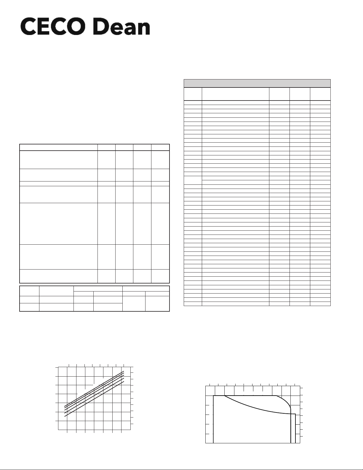
*GPM Flow Rate o Cooling Water Based on 70oF (21°C) Inlet Temp
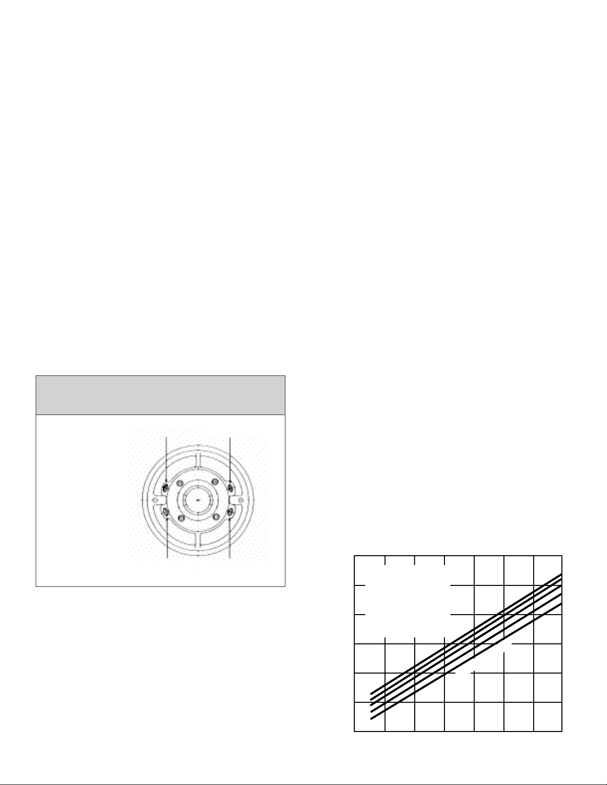
S al Chamb r T mp ratur VS. Pumping T mp ratur
with respect to the GPM of cooling water flowing through
the cooling jacket surrounding the seal chamber.
Specifications are subject to change without notice
PUMPING TEMPERATURE –°F
PUMPING TEMPERATURE – °C.
SEAL CHAMBER TEMPERATURE °C
100 150 200 250 300 350 400 450
200 300 400 500 600 700 800
350
300
250
200
150
100
50
180
160
140
120
100
80
60
40
20
0
1
2
3
4
5
4
8
11
15
19
COOLING WATER FLOW RATE°C
SEAL CHAMBER TEMPERATURE °F
GPM
1/min
MATERIAL SPECIFICATIONS (REFER TO NUMBERS IN PARENTHESES)
Pumping T mp ratur - °F
R5000 S ri s Pumps – Allowabl Working Pr ssur VS Pumping T mp ratur
Pumping T mp ratur - °C
-50 50 100 150 200 250 300 350 400 450
4000
3500
3000
2500
2000
1500
1000
500
0
Carbon Steel (Classes 40 & 41)
Carbon Steel Max. Temp.
316SS (Class 50)
316SS Max. Temp.
-100 100
100
200
200
300
300
400
400
500
500
600 700 800 900
0
0
Minimum Temperature Limit - 20 Deg. F.
Working Pr ssur - P.S.I.G.
Working Pr ssur - KPa
(1) Cast Iron (12) Manila Paper
(2) AISI 1020 (13) Fibre Sheet — Non-Asbestos Fibre
(3) 316SS — ASTM #A744 Grade CF8M (14) Buna N Rubber
(4) AISI 4140 ASTM #A193-B7 Steel (15) Steel Finned Stainless Steel Tube with Steel End Fittings
(5) ASTM #A194 Grade 2 Steel (16) Ductile Iron — ASTM-A536 Class 65-45-12
(6) ASTM #A216 Grade WCB Cast Steel ( -20 + 800°F ) (17) ASTM A743 Grade CA15 or Grade CA6NM
(7) Hardened Iron (18) ASTM A743 Grade CA40 Hardened to 475/525 Brinell
(8) AISI—316SS (19) AISI — 420 Stainless Steel
(9) AISI—304SS (20) ASTM A743 Grade CA40
(10) Alloy Steel —125 000 TS. 100 000 YP
(11) Grafoil — Registered trademark of Union Carbide Corp.
SEAL CHAMBER PRESSURE - R5000 SERIES PUMPS
**With Impeller Balance Holes—Seal Chamber Pressure Equals Pump Suction Pressure Plus .06 x Pump Developed Pressure in PSI
Without Impeller Balance Holes—Seal Chamber Pressure Equals Pump Suction Pressure Plus .75 x Pump Developed Pressure in PSI
Pumps are normally furnished with balance holes
3 Impeller
*4 Impeller Key
5 Casing
5A Casing Drain Plug
5C Casing Stud Nut
5D Casing Stud
*6 Casing Back Cover Ring
6A Casing Ring
7 Cradle Spacer
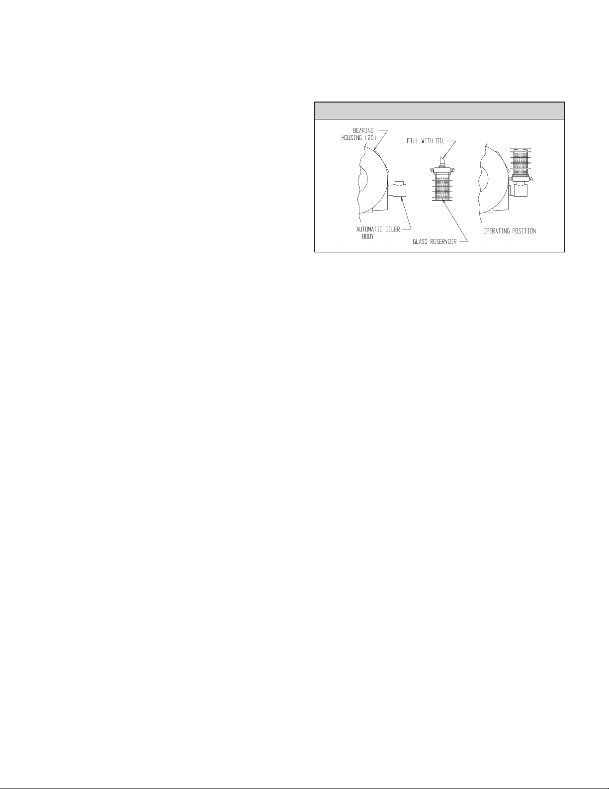
7A Automatic Oiler w/Bull’s Eye Gauge
7G Spacer to Bearing Housing Capscrew
9 Bearing Housing Foot
*10 Shaft Sleeve
*10K Shaft Sleeve Key
*12 Impeller Bolt (Nut on R5170)
*12A Impeller Washer
*12B Impeller Lock Washer
*12C Impeller Washer Pin
Seal Chamber Gland
Packing Gland
14 Gland Stud
15 Gland Nut
*17 Lantern Ring
22 Casing Back Cover
*22A Back Cover to Cradle Cap Screw
*25 Radial Bearing
*25A Thrust Bearing
*26 Bearing Housing
*27 Seal Ring
*28 Bearing End Cover
*28A Bearing End Cover Cap Screw
*29 Pump Shaft
*31 Thrust Bearing Lock Nut
*31A Thrust Bearing Lock Washer
*54 Throat Bushing
56 Casing Foot
*56B Casing Foot Dowel
*75B Retaining Ring (All Except R5240)
*76 Labyrinth Seal—Front
*76A Labyrinth Seal—Rear
77 Casing Gasket—Spiral Wound
*77B End Cover Gasket
*80 Bearing Housing Vent
*87 Impeller Ring—Back
87A Impeller Ring—Front
95A Mechanical Seal Stationary
95B Mechanical Seal Rotary
*109 Oil Cooler—(SS Tubing with Steel Fins)
302 Throttle Bushing—Gland
* Denotes parts interchangeable in all pump sizes of same type. † Registered Trademark of the E.I. DuPont Co.
STANDARD MATERIALS OF CONSTRUCTION
Carbon St l
w/ C.I. Trim
(C.I. 40)
Part NamPart No. Carbon St l
w/ 11-13 Cr.
Trim (C.I. 41)
316 SS
(C.I. 50)
C.I. (1)
Steel (2)
Steel (6)
Steel (2)
Steel (5)
Steel (4)
Iron (7)
Iron (7)
Steel (6)
Alum/Glass
Steel (2)
C.I. (1)
316 (8)
304 (9)
Steel (2)
Steel (2)
316 (8)
304 (9)
316 (8)
Steel (6)
Steel (4)
Steel (5)
C.I. (1)
Steel (6)
Steel (2)
Steel
Steel
C.I. (1)
C.I. (1)
C.I. (1)
Steel (2)
Steel (10)
Steel (2)
Steel (2)
C.I. (1)
C.I. (1)
Steel (2)
Steel
Bronze & Viton †
Bronze & Viton †
316 & Grafoil (11)
Buna (14)
Steel
Steel (2)
Steel (2)
Carbon
SS & Steel
—
—
11-13 Cr. (17)
Steel (2)
Steel (6)
Steel (2)
Steel (5)
Steel (4)
11-13 Cr. (18)
11-13 Cr. (18)
Steel (6)
Alum/Glass
Steel (2)
C.I. (1)
316 (8)
304 (9)
Steel (2)
Steel (2)
316 (8)
304 (9)
316 (8)
Steel (6)
Steel (4)
Steel (5)
C.I. (1)
Steel (6)
Steel (2)
Steel
Steel
C.I. (1)
C.I. (1)
C.I. (1)
Steel (2)
Steel (10)
Steel (2)
Steel (2)
11-13 Cr. (19)
C.I. (1)
Steel (2)
Steel
Bronze & Viton †
Bronze & Viton †
316 & Grafoil (11)
Buna (14)
Steel
11-13 Cr. (20)
11-13 Cr. (20)
Carbon
SS & Steel
—
—
316 (3)
316 (8)
316 (3)
316 (8)
Steel (5)
Steel (4)
316 (3)
316 (3)
Steel (6)
Alum/Glass
Steel (2)
C.I. (1)
316 (8)
304 (9)
316 (8)
316 (8)
316 (8)
316 (8)
316 (8)
316 (3)
304 (9)
304 (9)
316 (3)
316 (3)
Steel (2)
Steel
Steel
C.I. (1)
C.I. (1)
C.I. (1)
Steel (2)
316 (8)
Steel (2)
Steel (2)
316 (8)
C.I. (1)
Steel (2)
Steel
Bronze & Viton †
Bronze & Viton †
316 & Grafoil (11)
Buna (14)
Steel
316 (3)
316 (3)
Carbon
SS & Steel
—
—
13
700 Emlen Way, Telford, PA 18969 USA
Phone: 215.723.8155, Fax: 215-723-2197, Toll Free:800-392-7621