Ceco Sethco P90S User manual

PD-381-02B
MODEL P90S
STAINLESS STEEL 316
DRUM PUMP
PA RTS LIST
February 1, 2000
Supersedes PD-381-02A, dated 6-1-97
ALWAYS SPECIFY MODEL, SERIAL NUMBER, NAME PART NUMBER AND THIS DRAWING NUMBER WHEN ORDERING.
P
90
DRUM
PUMP
Features
115V AND 230V MOTOR
SEALLESS
CONTINUOUS DUTY SERVICE
SELF PRIMING
POWERFUL DOUBLE
INSULATED 1150 WATT MOTOR
STAINLESS STEEL
CONSTRUCTION
MADE IN U.S.A.
CECO Sethco:700 Emlen Way, Telford, PA 18969
Tel: 215-723-8155 •Website: www.cecoenviro.com • Email: gl dmdf q@onececo.com

NOTES
1. Includes 1 each of items 31, 32, 36, 37, 40 and 2 each of
item 33.
2. Includes 1 each of items 31A, 32A, 36, 37, 40 and 2 each of
item 33.
3. Includes items 36, 37, 40.
4. Included with item 51.
5. Included with item 52.
6. Includes items 31-50.
7. Includes items 31A-50.
8. Does not include plug.
MAINTENANCE
DISASSEMBLY
1. Isolate pump electrically.
2. Separate motor from pump.
—CAUTION—
WEAR PROTECTIVE CLOTHING AND EQUIPMENT
ALWAYS DISCONNECT FROM POWER SOURCE
BEFORE SERVICING.
3. Relocate motor to repair area.
4. Remove screws (47, 48).
5. Remove upper half of motor housing.
6. Remove screws (46) and clamps (38, 39).
7. Remove brush assemblies (33).
8. Remove field (32) and armature (31).
INSPECTION
1. Check brushes (33) for rough wear or cracks, and free travel.
2. Check all connections.
3. Check all wires for cuts or nicks.
4. Check bearings (36, 37) by rotating with fingers. If there is a
bumpy or sandy feeling, replace.
5 Check armature (31) If commutator's surfaces are rough or
winding wire burned, replace armature.
6 Check field (32) If winding is burned, replace.
7 Check switch (41) If rocker does not stay in ON or OFF position
replace switch.
ASSEMBLY
1. Slide armature (31) into field (32) with white wire facing
commutator.
2. With white wire facing up, place armature (31) and field (32) into
motor housing (43) so that bearings (36,37) and field (32) are
properly seated.
3. Install clamps (38, 39) using screws (46).
4. Check armature (31) for free rotation.
5. Install brush assemblies (33).
6. Install switch (41) with yellow sticker facing up.
7. Press black and white wires (black wire leading to the switch)
into the groove in motor housing, making sure no wire can come
in contact with armature.
8. Place O-ring (35) in upper half of motor housing.
9. Place two halves of motor housing together, properly aligned.
10.Secure motor housings with screws (47, 48).
11. Snap in switch (41) with cover (42).
TESTING
Jog motor and listen for smoothness of running.
Congratulations:
You have just purchased a quality industrial drum pump, manufactured to exacting standards.
To provide for the safe operation and prolong the life of your purchase, please review the operating instructions
and become familiar with the P90 drum pump.
Thank you for choosing a Sethco product. We look forward to serving your future requirements
ITEM NAME REQ’D PART NUMBER
31 Armature - 115V (Note 4) 1 020P990346-195
31A Armature - 230V (Note 5) 1 020P990971-195
32 Field - 115V (Note 4) 1 302P990347-195
32A Field - 230V (Note 5) 1 302P99068-195
33 Brush & Holder Assy. (Note 4 & 5) 2 032P80-195
34 Spade Connection 1 171P12646-195
35 O-Ring 1 590P2210-341
36 Bearing (Note 4 & 5) 1 080P622149-720
37 Bearing (Notes 4 & 5) 1 080P621221-720
38 Clamp 1 130P80716-720
39 Clamp 1 130P8004-720
40 Retaining Ring (Notes 4 & 5) 1 700P622167-720
41 Switch-115V 1 871P808-195
41A Switch - 230V 1 871P804≠1-195
42 Cover 1 140P101710-195
43 Motor Housing 1 450P80-593
44 Bend Relief 1 700P182-195
45 Cord - 115V 1 132P18216-195
45A Cord-230V (Note 8) 1 132P18217-195
46 Screw 4 790P101604-720
47 Pan Head Screw 4 790P10102-680
48 Pan Head Screw 3 790P101006-680
50 Connector 1 171P311-195
51
Armature - Field Set, 115V (Note 1)
1578P80-195
52
Armature - Field Set, 230V (Note 2)
1578P801-195
53 Motor Assy. - 115V (Note 6) 1 381-B
54 Motor Assy. - 230V (Note 7) 1 381-C
115V and 230V MOTORS
MOTORS
WARNING!
DO NOT USE WHEN
COMBUSTIBLE OR
FLAMMABLE
CONDITIONS EXIST.
MOTOR CAN SPARK!
EXPLOSION OR
INJURY OR DEATH
CAN OCCUR.

5
15 16
4
18
3
1
2
13
10
12
9
6
7
8
11
14
19
DISASSEMBLY:
1. Separate motor from pump by unscrewing collar, (8) from motor. Gently pull pump from motor.
2. Remove retaining ring (15) from lower head. Remove screw (16) and set aside
3. Place a wide screwdriver in coupling spider (6) to keep it from turning and unscrew impeller (5)
(left hand thread) using a screwdriver between two of the vanes of the impeller.
4. Remove coupling spider (6) by lifting out.
5. Hold coupling (7) to prevent rotation Insert a small screwdriver in the slot of coupling shaft (14)
and unscrew coupling
6. Unscrew ball bearing housing (17) from pump and remove complete assembly. including shaft,
from pump.
7. Place a small screwdriver in slot of coupling shaft (14) and, using a small pair of pliers, grip
shaft (2) just below the ball bearing housing (17). Unscrew pump shaft.
8. Insert the head of a small common nail into the bearing retainer (4). Hook the back end of
bearing retainer and pull it out along with the bearing (3)
9. Before dismantling ball bearing housing (17) inspect ball bearings (11) as follows: Grasp
coupling shaft (14) and rotate ball bearing housing (17) by hand slowly. Rotation should
be absolutely smooth with no roughness. If continued operation is questionable, replace ball
bearings (11).
NOTE: These ball bearings are lubricated with special grease. Replace with original factory
quality parts only. We strongly recommend that you replace ball bearings and seal together as
a complete assembly with coupling shaft. See item 14. Otherwise see ball bearing and seal
replacement instructions below.
BALL BEARING and SEAL REPLACEMENT:
1. Remove retaining ring (10) from both ends of ball bearing housing (17).
2. Remove bearing housing components by pushing out coupling shaft (14) and ball
bearings (11) simultaneously
3. While supporting a ball bearing (11) and seal (13), remove from coupling shaft (14)
4. Repeat step 3 for other ball bearing (11).
5. Replace ball bearings by pressing on to shaft in the same manner in which they were first
removed .
6 Once ball bearing (11) and seal (13) are located on coupling shaft (14), press entire
assembly into bearing housing (17) and install retaining rings (10).
REASSEMBLY:
(1) To assemble bearing (3) to bearing retainer (4), insert bearing into 3/8 inch diameter end of
bearing retainer and pull 1" of bearing through slot Wrap 1" end of bearing (3) onto bearing
retainer (4) for 3/4 of one turn. Bearing must be wrapped on the mid section of bearing retainer
so as not to interfere with shoulders at each end.
2. Install bearing (3) and bearing retainer (4) assembly into pump tube (1)
3. Screw shaft (2) into coupling shaft (14).
4. Carefully guide the shaft (2) into the center of pump tube (1) without force. Then secure ball
bearing housing (17) by screwing into pump tube
5. Install coupling (7) onto coupling shaft (14).
6. Insert coupling spider (6) into coupling (7).
7. While holding coupling spider (6), install impeller (5) onto shaft (2) (left hand thread) tighten
impeller using a screwdriver between two vanes of the impeller.
8. Install screen (16) and retaining ring (15) into pump tube (1) tighten impeller using a screwdriver
between 2 vanes of the impeller.
ITEM QTY DESCRIPTION MATERIAL 381-09040-ST
11 Pump Tube Assemby SS-316 910P9 040-670
21 Shaft Carp-20 850P800241-130
31 Bearing (Spiral) Teflon 080P102432-770
41 Bearing Retainer Teflon 700P8004-770
51 Impeller PVDF 430P97-384
61 Coupling Spider Nylon 170P801-585
71 Coupling Nylon 170P8051618-525
81 Collar Poly-pro 160P644-571
91 Retaining Ring Steel 700P5108196-880
10 2 Retaining Ring Steel 700P510039-720
11 2 Bearings 33-304 080P10268-680
12 1 Retaining Ring Steel 700P3000102-720
13 1 Seal Vapor Teflon 760P102017-770
14 1 Coupling Shaft SS-316 850P10201-670
15 1 Retaining Ring SS-316 700P80-670
16 1 Screen SS-316 870P102015-670
17* 1 Bearing Housing SS-316 440P201373-670
18* 1 Inner Tube Assembly SS-316 981P8041-670
19* 1 Teflon Spacer Teflon 770P80-770
20 (not shown) 1
Coupling/shaft/bearing/seal assembly
various 853P201427-671
*ITEMS (18) and (19) are part of item 1 (pump tube assembly) but can be
ordered separetly as spare parts.
†Includes item 10, 11, 13, and 14 fully assembled.
17

TROUBLE SHOOTING
Problem: Pump doesn’t pump
Probable Cause Remedy
1. Motor not turning 1. Check electric outlet & plug
2. Check rocker switch
3. Unplug motor and remove
pump, keeping fingers clear of
spine. Plug in and test motor.
4. Return to factory
2. Motor bearing “frozen” 1. Return to factory
3. Motor brushes worn 1. Return to factory
4. Pump coupling sheared 1. Replace
5. Solution solidified in pump 1. Flush
6. Impeller damaged 1. Replace
7. Pump bearings “frozen” 1. Replace
8. Debris in suction 1. Unplug pump motor & clear
9. Hose crimped 1. Straighten
10.Less than 2” of liquid in drum 1. Tilt drum
CECO Sethco:700 Emlen Way, Telford, PA 18969
Tel: 215-723-8155 • Website: www.cecoenviro.com • Email: gl dmdf q@onececo.com
1. KNOW YOUR UNIT—Read owners manual carefully. Learn its
applications, limitations, capabilities and proper use.
2. HAZARDOUS LOCATIONS—Use hazardous duty motor in
locations where fire or explosion hazards may exist due to
flammable gases or vapors. Use air motor in a dust environment.
Use stainless steel pump for flammable liquids.
3. KEEP WORK AREA CLEAN—Cluttered areas and benches invite
accidents.
4. AVOID DANGEROUS ENVIRONMENT—As with any electric
power tool, don’t expose the unit to rain.
5. KEEP BYSTANDERS AWAY—All visitors and unauthorized
persons should be kept a safe distance from work areas.
6. STORE PROPERLY—As with any power tool, when not in use,
unit should be cleaned and stored in a dry place away from
unauthorized personnel.
7. DON’T FORCE TOOL—Do not use pump to break ice in drums or
break up sludge masses. Rapid wear and/or damage will occur
when pumping abrasives or thick materials.
8. WEAR PROPER APPAREL—No loose clothing or jewelry to get
caught on hoses or cords. Rubber gloves, aprons and footwear
are recommended.
9. USE SAFETY GLASSES— The operation of
any power tool can result in foreign objects
(splashing) being thrown into the eyes, which
can result in severe eye damage. Always wear
safety glasses with eye shields before com-
mencing power tool operation. We recommend
Wide Vision Safety Mask for use over
spectacles, or safety glasses.
10. DON’T ABUSE CORD—Never carry tool by
cord or yank it to
disconnect from receptacle. Keep cord from heat
and sharp edges
.
11.SECURE PUMP AND HOSE—When not pumping from a drum,
secure pump to prevent accidental immersion into tanks. Secure
discharge end of hose to prevent “whipping” of hose.
Secure hose clamp tight.
12.DO NOT IMMERSE—pump into fluid above pump discharge.
Do not immerse motor in any fluid.
13. DON’T OVERREACH—Keep proper footing and balance at all times
.
14.MAINTAIN EQUIPMENT with care — Keep pump clean for best
performance. Follow maintenance instructions.
15. DISCONNECT MOTOR—when not in use and before servicing,
remove plug from power supply.
16. AVOID ACCIDENTAL STARTING—Don’t carry plugged-in tool
with finger on switch. Be sure switch is off when plugging in.
17. KEEP HANDS AND FINGERS FROM IMPELLER.
18. KEEP FACE AWAY—Don’t look into hose, pump discharge or
suction.
19. REVIEW MATERIAL SAFETY DATE SHEET OF THE PRODUCT
TO BE PUMPED
.
INTRODUCTION
DOUBLE INSULATION is a concept in safety, in electric power tools,
which eliminates the need for the usual three wire grounded power
cord and grounded supply system. Wherever there is electric current
in the tool there are two complete sets of insulation to protect the user.
All exposed metal parts are isolated from the internal metal motor
components with protecting insulation.
IMPORTANT — Servicing of a motor with double insulation requires
extreme care and knowledge of the system and should be performed
only by a qualified service technician. For service, we recommend
returning your motor to Sethco.
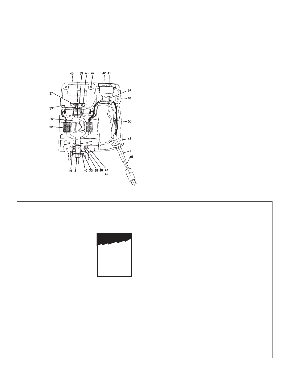
HAZARDOUS DUTY MOTOR — When service is required, return to
factory. NOTE: This motor is equipped with a thermal overload sen-
sor. When activated the pump will stop and re-start automatically
when the motor cools.
Problem: Pump capacity reduced
1.
Worn impeller and/or suction intake
1. Replace
2. Low voltage 1. Check outlet
3. Thick fluids 1. Consult factory
4. Hose crimped 1. Straighten
5. Pump bearings worn 1. Replace
6. Motor bearing worn 1. Return to factory
7. Suction partially clogged 1. Unplug motor and clean
8. Discharge line restricted 1. Unplug motor and clear
CAUTION: Read rules for safe operation and instructions carefully
WEAR YOUR
SAFETY GLASSES
SWITCH
The standard 115V & 230V electric P90 motor is equipped with a
rocker switch located in the upper part of the handle. Press the upper
part of the rocker to start and the opposite half to stop. The switch
has a built in circuit breaker which will trip the switch in the event of
an overload. Be sure switch is in the “off” position before connecting
to power supply.
SWITCH
The hazardous duty motor is equipped with a rotary switch. Make sure
the switch is in the “off” position before connecting to power supply.
OPERATION
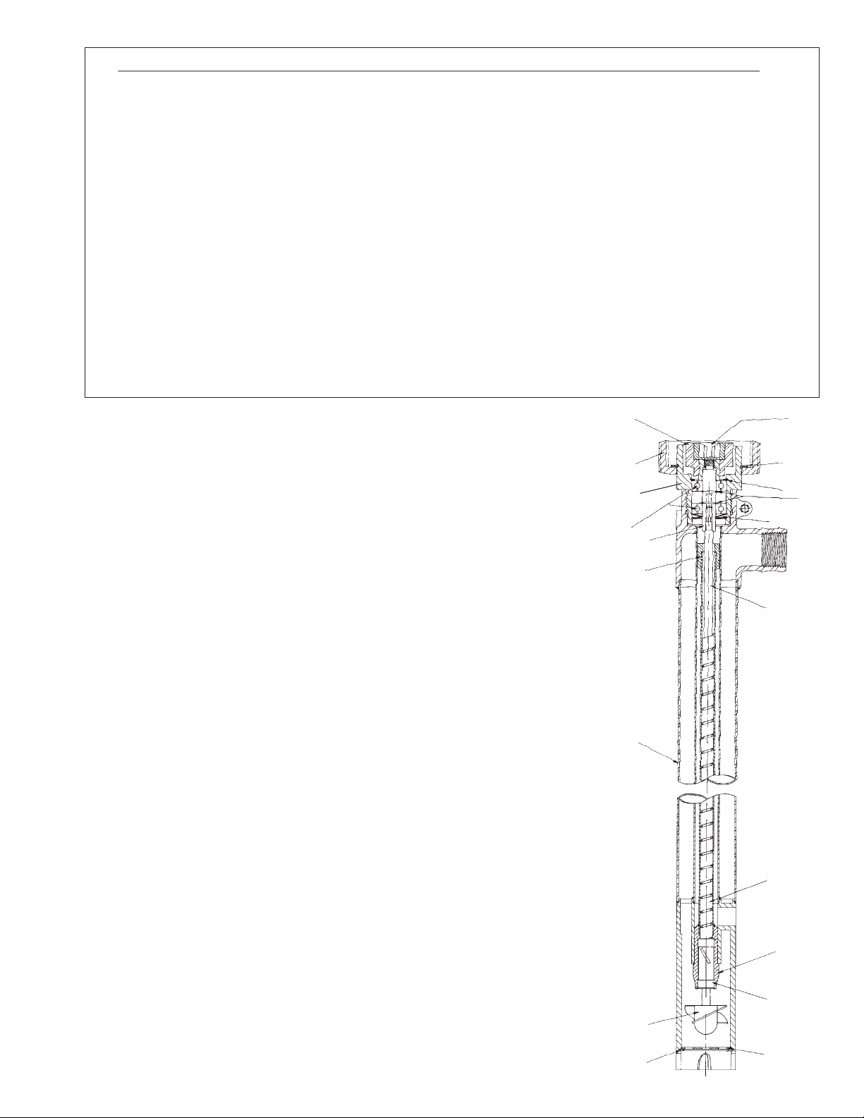
1. Align coupling splines and motor spline.
2. Align motor key and pump head.
3. Insert pump head into motor and secure with collar (1).
4. Slip hose clamp over hose end.
5. Slip hose onto pump discharge. Push hose onto full length of
discharge nipple. (1-1/8 inches).
6. Align hose clamp between discharge nipple “barbs”.
7. Tighten hose clamp.
START-UP (CAUTION — OBSERVE SAFETY RULES)
1. Insert pump into drum. 2. Control or secure discharge hose.
3. Plug in motor. 4. Switch unit on.
STOPPING
1. Switch unit off. 2. Unplug motor.
3. Lift pump from fluid slowly; allowing pump to drain.
STORAGE
1. Run pump in a rinsing solution for 30 seconds with discharge hose
open and 30 seconds with discharge hose closed.
2. Allow pump to drain.
3. Store in a secure area to prevent unauthorized use.
MAINTENANCE
When servicing, replace with original factory quality parts only. Only
the parts shown in the materials list are intended to be replaced by
the customer. The standard 115V & 230V motor is equipped with a
“DOUBLE INSULATION” system and should be serviced only by a
qualified service technician.
STAINLESS STEEL P90 DRUM PUMPS - SAFETY RULES
Other Ceco Water Pump manuals

Ceco
Ceco DEAN PUMP R5000 Series Instruction manual

Ceco
Ceco Dean Pump R4000 Series User manual

Ceco
Ceco Sethco 2500 Series User manual

Ceco
Ceco Dean Pump pH2110 Series Instruction manual

Ceco
Ceco Fybroc 8500 Series User manual

Ceco
Ceco Dean Pump M300 Instruction manual

Ceco
Ceco Fybroc 1530 Series User manual

Ceco
Ceco Sethco PMSP-510 User manual

Ceco
Ceco DEAN PUMP RA Series User manual
Popular Water Pump manuals by other brands

Kamoer
Kamoer X1 quick start guide

Pfeiffer Vacuum
Pfeiffer Vacuum HENA 202 operating instructions

ARO
ARO TWO-BALL PUMP SERIES 650963-XXX-B Operator's manual

Macnaught
Macnaught FTWM120-001 instruction manual

Rietschle
Rietschle TR-V Series operating instructions

Commodity Axis
Commodity Axis MillionAir ViaAqua DC-250 quick start guide