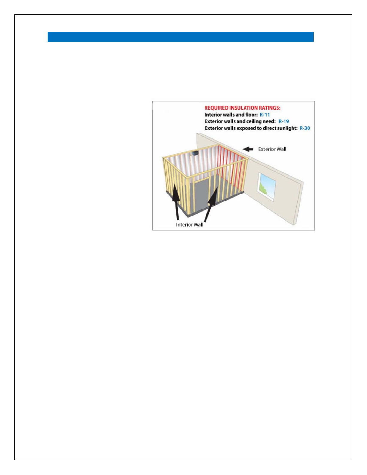
CellarPro 3000Sqc User manual

1 V9.20
ControltheElements
QuickConnect
Split Refrigeration Systems
Owner’s Manual

2 V9.20
C O N G R A T U L A T I O N S !
Thank you for purchasing a new CellarPro cooling system.
Please take a minute to read through this Owner’s Manual before you unpack,
install and turn on your Cooling Unit.
If you have any questions about your new cooling unit, it is likely that you will find the
answers in this Owner’s Manual. We also have more information on our website,
including the latest version of the Owner’s Manual, at www.cellarpro.com/customer-
service .
If you still have questions, please don’t hesitate to contact your dealer or CellarPro
directly. We can be reached during normal business hours at 707.794.8000 x3. You
also may contact us anytime via email at [email protected].
Contact Information:
CellarPro Cooling Systems
1445 N. McDowell Blvd
Petaluma, CA 94954
707.794.8000 x3
Email: [email protected]
Website: www.cellarprocoolingsystems.com

3 V9.20
Table of Contents
I. Package Contents 4
II. Specifications and Cut Sheets 5
III. Cellar Construction 8
IV. Installation Instructions 10
V. Operating Instructions 25
VI. Troubleshooting 32
VII. Limited Warranty 37

4 V9.20
I. Package Contents
BOX 1:
3000Sqc
4000Sqc
3000Shqc
4000Shqc
DESCRIPTION QTY QTY
Evaporator 1 1
Side Mounting Bracket (attached to unit) 2 n/a
Wall Bracket Horizontal n/a 2
Hole Plug 1" Horizontal n/a 2
Locknut Serated Horizontal n/a 2
Wall Mounting Screws 10 6
Drain Tubing (attached to unit) 10 ft. 10 ft.
Power Cord (attached to unit) 8 ft. 8 ft.
Owners Manual 1 1
4" insulation sleeve 1 1
Butyl 18 in n/a
Adhesive backed foam strips:
(1) x 9.25”x1.5”x1.5” and (1) x 3.75”x1.5”x1.5” n/a 1 Set
Large tie wraps 2 2
Remote Display Kit 1 (optional) 1 (optional)
Bottle Probe 1 (optional) 1 (optional)
Bottle Probe Extension Cord 1 (optional) 1 (optional)
BOX 2:
DESCRIPTION QTY QTY
Condensing Unit w/Outdoor Hood Assembled 1 1
Power Cord (attached to unit) 8 ft. 8 ft.
QuickConnect Line Set 1 Set 1 Set
BOX 3 (Optional):
DESCRIPTION QTY QTY
Front Duct Hood Low RH 1 Set (Optional) 1 Set (Optional)
Front Duct Hood High RH w/Insulation 1 Set (Optional) 1 Set (Optional)
Ducting 1 Set (Optional) 1 Set (Optional)

5 V9.20
II. Specifications and Cut Sheets
Evaporator
Model
Dimensions
W x D x H (inches)
Weight
(lbs.)
MCA
System Running Amps
(with fan on “high”)
3000Sqc 16.6 x 12.6 x 22.1
(incl. mounting brackets) 40 1.29 6.2
4000Sqc 16.6 x 12.6 x 22.1
(incl. mounting brackets) 42 1.74 8.9
3000Shqc 30.4 x 14.4 x 13.2
(incl. mounting bracket) 63 1.29 6.2
4000Shqc 30.4 x 14.4 x 13.2
(incl. mounting bracket) 65 1.74 8.9
Condensing Unit with Hood
Model
Dimensions
W x D x H (inches)
Weight
(lbs.)
MCA
3000Sqc/Shqc
19.4 x 23.3 x 18.8
(with cover)
73 6.33
4000Sqc/Shqc 76 9.20
Notes
1) Separate 115V / 60HZ power supplies are required for the Evaporator and the
Condensing Unit.
2) A 15 amp circuit breaker is recommended for all Evaporator models.
3) A 15 amp dedicated circuit breaker (non GFI) is recommended for all Condensing
Units models.

6 V9.20
Evaporator Cut Sheets

7 V9.20
Condensing Unit Cut Sheet

8 V9.20
IV.III. Cellar Construction
Insulation
CellarPro cooling units are designed to be installed inside wine cellars that have
proper insulation, moisture barriers and an airtight seal from the environment
outside the cellar. Interior walls and floor should have a minimum of R-11
insulation, and a vapor barrier
on the warm side of the
insulation. The ceiling should
have a minimum of R-19
insulation and a vapor barrier
on the warm side of the
insulation. Doors also should
be insulated and tightly
sealed with weather
stripping around the
perimeter of the door.
Surface-mounted fixtures
are recommended over
recessed lighting, which can
allow air to leak into the
cellar.
It is important that all walls,
joints, doors and windows, electrical outlets and/or switches, pipes, vents and
light fixtures be sealed to prevent air and moisture from entering the cellar. If there is
a leak in the cellar, the cooling unit will build up excess condensation.
The drain line (shipped loose with the cooling unit) must be connected to the drain
pan (as shown in the installation section).
Fan Speeds
Your fan speed setting will depend on the thermal load on the wine cellar, and the
resulting BTU that is required to cool and maintain your wine cellar at the desired
temperature. If the unit is ducted, the high fan speed always should be used.
Ventilation
Adequate ventilation is critically important for the proper operation of your CellarPro
cooling unit.

9 V9.20
Outside the Cellar
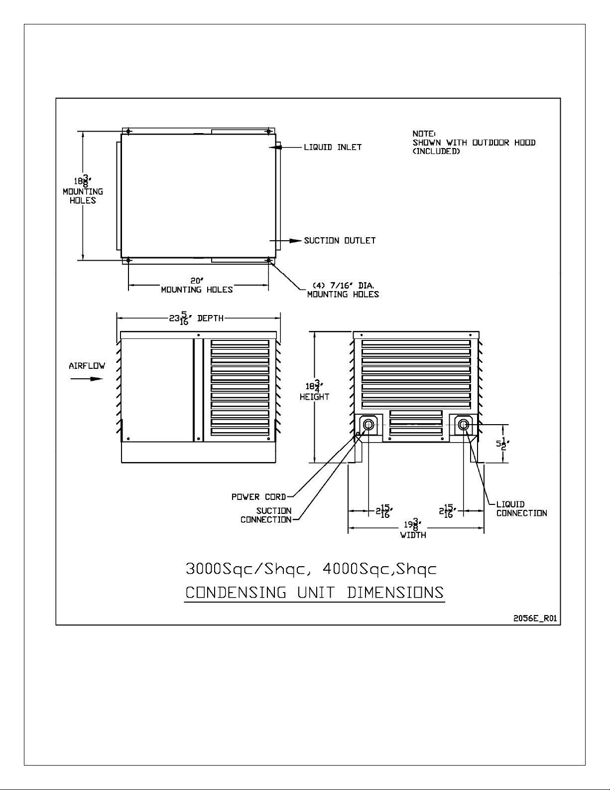
Condensing unit Air Exhaust. Condensing units create significant hot air which
must be exhausted into an appropriately-sized space in order for the heat to
dissipate. If the space is constrained and/or too small, the heat will not dissipate.
In this event, the cooling unit will be forced to re-circulate its hot air exhaust and/or
the static pressure will back up the cooling unit. If this happens, the cooling unit’s
ability to create cold air inside the cellar will be compromised.
Condenser Air Intake. The condenser coils require access to cool air in order for
the cooling unit to produce cold air. In addition, the cooling unit must be installed
so that, after its installation, the condenser coils are accessible for periodic cleaning.
The Condensing unit cannot be ducted.
Inside the Cellar
Evaporator Air Intake
.
When the warm air passes across the evaporator coils, heat
is removed from the air, and the resulting cold air is exhausted into the cellar. To
ensure proper airflow, minimum clearance of 12” is required in front of the cooling
unit.
Evaporator Air Exhaust.
Cold air is exhausted at the top front of the cooling unit.
Because CellarPro cooling units are located at the highest point inside wine cellars,
the cold air exhaust eventually will drop to the bottom of the cellar. To ensure proper
airflow and reduce temperature stratification inside the cellar, the space in front of
the cold air discharge should be clear of any obstructions, including wine bottles, wine
racks, etc.
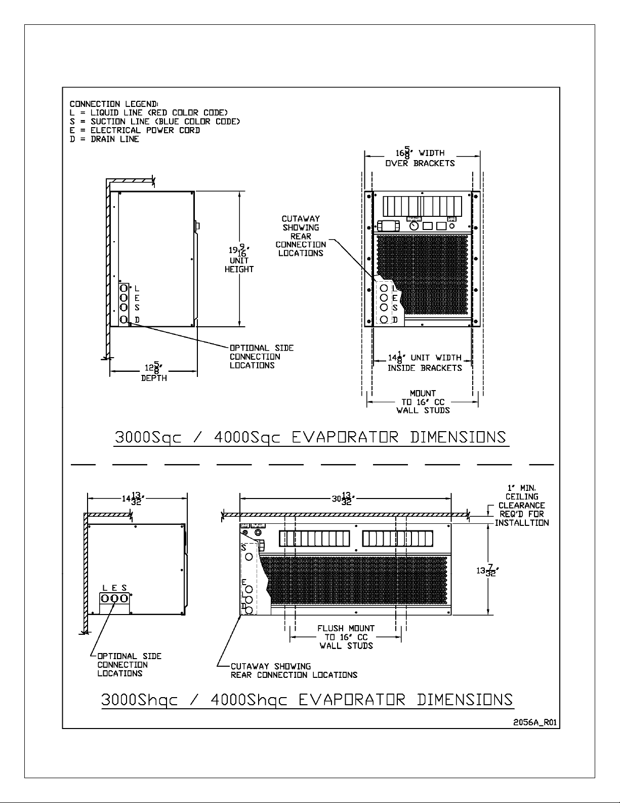
Ducting For the Evaporator (3000Sqc/4000Sqc Models). Cold air exhaust and
return (from the evaporator) can be ducted with our front duct hood up to 100
equivalent feet of total ductwork, or 50 equivalent feet for both the discharge and
return ducting, using 8” diameter insulated ducting. Our front duct kit is compatible
exclusively with our 3000Sqc and 4000Sqc cooling units. If you’d like to duct one
of our larger cooling units, please consider our AH6500 and AH8500 cooling units.
Before attaching the front duct hoods, remove the front grill (if present) from the
front of cooling unit.
Front duct kits should be paired with our remote control panel, which allows the
digital display to be installed remotely from the cooling unit, either inside or outside
the cellar. The remote comes standard with 10’ of wiring, and offer additional wiring
upon request. Front duct kits also should be used with our remote thermostat (aka
bottle probe), which comes standard with a 10 foot cord that can be plugged into
the cooling unit, and terminate inside the cellar to measure either air or liquid
temperature. Please note that the HY setting should be changed from the 4 to 1 if
the bottle probe will be inserted in liquid (see Advanced Operation for more
information).

10 V9.20
IV.IV. Installation Instructions
Condensing Unit Installation
The Condensing Unit is designed to operate outside the cellar in temperatures
ranging from 20°F to 110°F. With the addition of a fan cycling control (sold
separately), the unit can operate in temperatures ranging from 0°F to 110°F.
Indoor Installation
If the Condensing Unit is installed indoors:
The area must have suitable ventilation to maintain an ambient temperature of
110°F or less at the face of the coils.
If the area does not have adequate ventilation, a vent fan should be added to
supply fresh air to the space (suggested 600CFM).
A minimum of 12" of open air space around the perimeter of the condensing unit
is required.
Outdoor Installation:
If the Condensing Unit is installed outdoors:
Condensing units must be installed with the outdoor hood if the unit will be
located outdoors. PLEASE NOTE: Our units were not designed for, and our
warranty does not cover damage from, marine exposure (within 5 miles of the
ocean). In these environments, you will need an applied coating, such as
Insitu®, to protect against corrosion that is common in coastal regions.
A minimum of 12" of open air space around the perimeter of the outdoor hood is
required.
Evaporator Unit Installation
As warm air rises to the top of the cellar, the cooling unit pulls the warm air through
the evaporator coil and removes the heat from the warm air. Once cooled, the cold
air is discharged from the front of the cooling unit and circulates through the cellar.
Therefore, we recommend mounting the evaporator as close to the ceiling as
possible inside the cellar, so that cold air can drop down into the cellar, and the
cooling unit catches warm air as it rises to the ceiling.
To attach the evaporator to the wall, we provide the necessary hardware, which
differs based on the unit purchased.
Our 3000Sqc and 4000Sqc evaporators use side mounting brackets,
Our 3000Shqc and 40000Shqc evaporators use wall hangars
Specific instructions for each mounting method are as follow:

11 V9.20
Evaporator Connection Locations - 3000Sqc and 4000Sqc
Connection locations are specified when ordering the equipment and are
available in the following options:
Refrigerant connections rear or left side
Power cord rear or left side
Drain line rear, left side, or bottom.

12 V9.20
Evaporator Connection Locations - 3000Shqc and 4000Shqc
Connection locations are specified when ordering the equipment and are
available in the following options:
Refrigerant connections rear or left side
Power cord rear or left side
Drain line rear, or bottom (cannot exit the side).

13 V9.20
Evaporator Mounting Instructions - 3000Sqc and 4000Sqc
Mounting brackets, which attach to the sides of the evaporator, are provided to
mount the evaporator flush to a wall inside the cellar.

14 V9.20
Evaporator Mounting Instructions – 3000Shqc and 4000Shqc
A wall hanger, which attaches to the wall behind the evaporator, is provided to
mount the evaporators to the wall inside the cellar. First, the wall bracket is attached
to the wall, and then the evaporator slides onto the bracket. After the evaporator is
installed, two bottom nuts must be installed on the recessed anchor studs.

15 V9.20
Condensate Drain Line
The condensate drain line should drop, then rise (but stay below the height of the
fitting), and then drop again into an open drain. Then, fill the trap with water. The
condensate trap will allow any excess moisture inside the Evaporator to
overcome the static pressure and flow out of the drain line. Before putting the unit
into service, test for positive drainage by pouring water into the drain pan and
observing flow through to the final drain.

16 V9.20
Power Supply
The Evaporator and Condensing units are separately powered with 8’ power cords and
grounded plugs. No interconnecting wiring is needed between the Evaporator and
Condensing unit.
Evaporator Power:
Plug in the Nema 5-15P plug to a shared or dedicated 15 amp receptacle
Condensing Unit Power:
Plug in the Nema 5-15P plug to a dedicated non-GFI 15 amp receptacle.
The Evaporator turns on and off based on the digital display controls, and the
Condensing Unit turns on and off based on suction pressure, as follows:
The Evaporator includes a factory installed liquid line solenoid valve (LLSV), which is
controlled by the Evaporator temperature controller. The Condensing unit is
controlled by a low pressure switch which reacts to the suction pressure and senses
whether the LLSV is open or closed.
When the Evaporator temperature set-point is reached and the Evaporator turns off,
the LLSV closes, causing the system to pump down until the low pressure switch
shuts off the Condensing unit.
When the Evaporator turns on, the LLSV opens, causing the suction pressure to rise
and activate the Condensing unit.

17 V9.20
Wiring Diagram

18 V9.20
QuickConnect Line Set
The Evaporator, Condensing Unit, Liquid Line and Insulated Suction Line (together the
Line Sets) are factory charged and shipped with R-134a refrigerant. The components
must be installed together as a complete CellarPro system. Do not substitute
components or use these components in a different split system. If any damage to the
components occurs that causes a loss of refrigerant, only a qualified HVACR service
technician certified to handle R-134a can perform the repairs.
Follow the installation instructions in sequence to ensure proper system
operation:
1. Determine the final locations where the Evaporator and Condensing units will be
mounted, and verify that the QuickConnect Line Set has sufficient length to
interconnect the two units. If the line set is not long enough, do not proceed.
Contact CellarPro for immediate assistance.
2. Reference the Evaporator Mounting and Evaporator Connection diagrams for
the model being installed. For rear connection configurations it is important to
properly locate the wall cutouts using the locating hole for the mounting bracket as
dimensioned on the diagrams. The diagrams also provide maximum outer
diameter dimensions for planning wall cutouts for side or bottom connection
configurations.
3. Make the connection cutout through the wall, and pull the Line Set through the
cutout into the cellar. If the drain line and/or power cord are configured out the
rear, feed these through the cutout from the evaporator to the outside of the cellar.
4. Locate the 4” tube insulation sleeve and long wire ties included in the parts kit.

19 V9.20
5. Identify the insulated Suction line (marked BLUE on the female connector) and
slide the 4” tube insulation sleeve over the Suction line on the side where it will
connect to the evaporator.
6. Identify the male Suction line connection on the rear or optional left side of the
evaporator (marked BLUE on the male connector), and attach the female
Suction line connection to the male connection. STOP AND MAKE SURE
YOU ARE ATTACHING BLUE TO BLUE. Hand thread at first to get the
threads started without cross threading. Once it is too hard to turn by hand,
use a crescent wrench until the connection stops tight - do not apply so much
force that the male connection starts to turn. Note that it is only necessary to
apply the wrench to the female connector, the male connector is locked in place
and should not be adjusted.
3000/4000SqcSuction
RearConnection(Blue)
3000/4000ShqcSuction
RearConnection(Blue)

20 V9.20
7. Once the Suction line is attached to the evaporator, slide the 4” tube insulation
sleeve so that it covers the metal connections that were just installed and one
end is flush to the unit housing. Use two tie wraps to secure the insulation in
place. If you forgot to pre-install the insulation sleeve before making the suction
line connection to the evaporator, it is acceptable to slit the insulation and wrap
around the coupling, provided that the seam is sealed tight. Insulating the
suction connection is essential to avoid condensation issues.
8. Identify the Liquid line (marked RED on the female connector). This line is not
insulated.
9. Identify the male Liquid line connection on the rear or optional left side of the
evaporator (marked RED on the male connector), and attach the female Liquid
line connection. To the male connection. STOP AND MAKE SURE YOU ARE
ATTACHING RED TO RED. Follow the same process to tighten the
connection.
3000/4000SqcLiquid
RearConnection(Red)
3000/4000ShqcLiquid
RearConnection(Red)
This manual suits for next models
3
Table of contents
Other CellarPro Refrigerator manuals