Celli Post-Mix POLO L Series User manual

USE AND
USE AND
MAINTENANCE MANUAL
MAINTENANCE MANUAL
USE AND
USE AND
MAINTENANCE MANUAL
MAINTENANCE MANUAL
30/10/201
@celli.cK
Code 077190
ORIGINAL INSTRUCTIONS
POLO L POST-MIX
POLO L POST-MIX
POLO L POST-MIX
Polo 50/L
Polo 20/L
Polo 30/L


Index
1
POLO 20-30-50/L POST-MIX
Index
1 - Safety .....................................................................................................................3
1.1 Intended use ..................................................................................................................... 3
1.2 Improper use .................................................................................................................... 3
1.3 List of hazards ................................................................................................................... 4
1.4 Residual risks .................................................................................................................... 6
2 - General information ............................................................................................... 7
2.1 Manufacturer’s details ........................................................................................................ 7
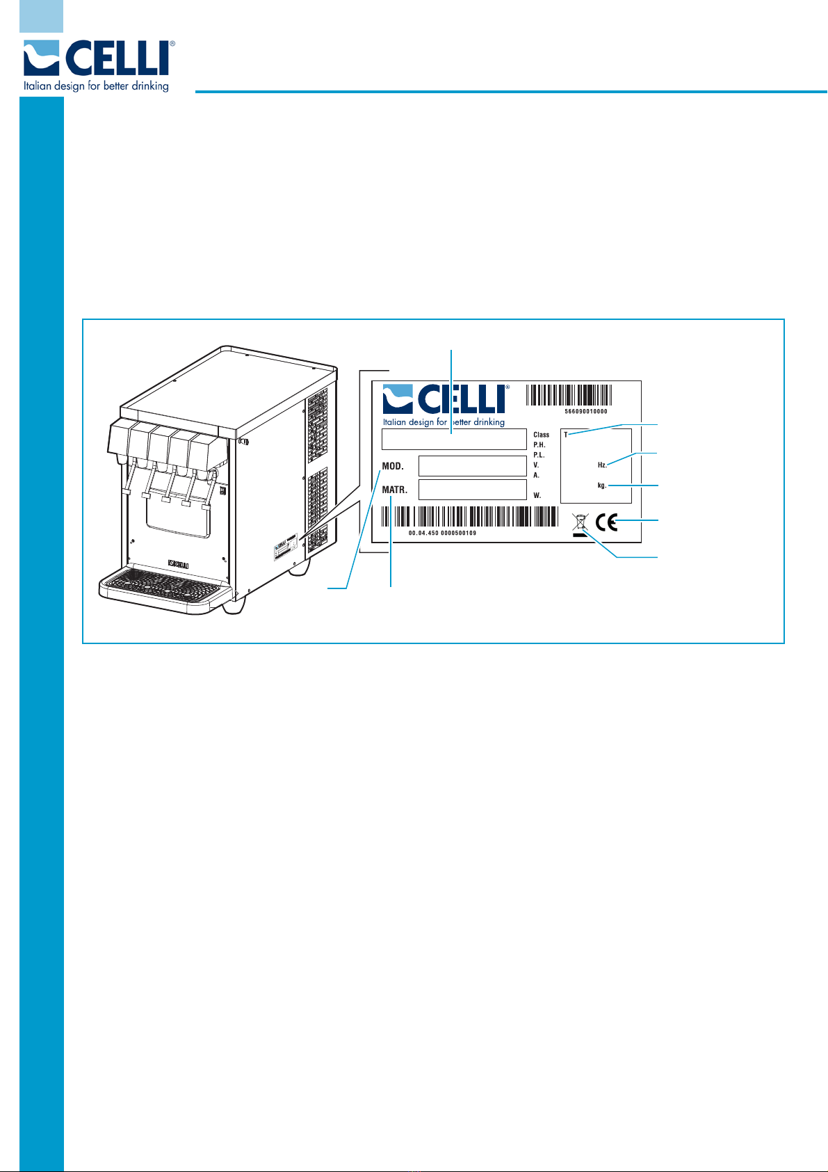
2.2 Machine identification......................................................................................................... 8
2.3 Warranty........................................................................................................................... 8
2.4 Symbols used in the manual ............................................................................................... 9
2.5 Staff qualification............................................................................................................... 9
3 - Description of the machine .................................................................................. 10
3.1 Main components of the POLO L POST-MIX range...............................................................11
3.2 Operating principle............................................................................................................13
3.2.1 Sound emissions ......................................................................................................16
3.3 Dimensions in mm (inches)................................................................................................17
3.3.1 POLO 20-L ...............................................................................................................17
3.3.2 POLO 30-L ...............................................................................................................17
3.3.3 POLO 50-L ...............................................................................................................17
3.4 Differential-switch power cord (optional) ............................................................................18
4 - Installation ........................................................................................................... 19
4.1 Checks and Unpacking ......................................................................................................19
4.2 Positioning .......................................................................................................................20
4.3 Environmental conditions...................................................................................................21
4.4 Electrical requisites ...........................................................................................................21
4.5 Connections .....................................................................................................................22
4.5.1 Preparing the machine..............................................................................................22
4.5.2 Water intake connection ...........................................................................................23
4.5.3 Connecting the syrup lines ........................................................................................25
4.5.4 Carbon dioxide (CO2) connection ...............................................................................26
4.5.5 Electrical connection .................................................................................................28
4.6 Adjusting the carbon dioxide (CO2) supply..........................................................................29
4.7 Checking for leaks.............................................................................................................29
4.8 Adjusting the dispensing valves .........................................................................................30
4.9 First start-up ....................................................................................................................31
5 - Using the machine................................................................................................ 32
5.1 Stopping the machine .......................................................................................................33
6 - Maintenance ......................................................................................................... 34
6.1 Scheduled maintenance.....................................................................................................34
6.1.1 Cleaning ..................................................................................................................35
6.2 Table of procedures ..........................................................................................................36

Index
2
Rev. 9/17
POLO 20-30-50/L POST-MIX
6.3 Replace the syrup tank .................................................................................................... 37
6.3.1 Replacing a steel keg ............................................................................................... 37
6.3.2 Replacing a BAG-IN-BOX ......................................................................................... 37
6.4 Replacing the carbon dioxide (CO2) bottle .......................................................................... 38
6.5 Replacing the water filter cartridge ....................................................................................38
6.6 Cleaning the spouts and mixers ........................................................................................ 38
6.7 Cleaning the condenser ................................................................................................... 39
6.8 Sanitising the dispenser .................................................................................................... 40
6.9 Cleaning and checking the liquid check valve...................................................................... 42
6.10 Cleaning the syrup connectors......................................................................................... 42
6.11 Replacing the water in the tank ....................................................................................... 43
6.11.1 Extraordinary maintenance ..................................................................................... 43
7 - Troubleshooting................................................................................................... 44
8 - Additional instructions......................................................................................... 46
8.1 Waste disposal ................................................................................................................. 46
8.2 Dismantling of the machine............................................................................................... 46
8.3 Disposal of electronic equipment (WEEE directive).............................................................. 47
9 - Annexes ............................................................................................................... 48
9.1 POLO L POST-MIX (still water kit) electrical diagram ........................................................... 48
9.2 POLO L POST-MIX (external still water pump) electrical diagram.......................................... 49
9.3 POLO L POST-MIX (6 valves with telemetry) electrical diagram ............................................ 50
9.4 POLO L POST-MIX (4 valves with telemetry) electrical diagram ............................................ 51
9.5 POLO L POST-MIX (5 valves with telemetry) electrical diagram ............................................ 52
9.6 POLO L POST-MIX (still water kit) hydraulic diagram........................................................... 53
9.7 POLO L POST-MIX (external still water pump) hydraulic diagram ......................................... 54
9.8 POLO L POST-MIX (with telemetry) hydraulic diagram ........................................................ 55

General information
7
POLO 20-30-50/L POST-MIX
2 - General information
The Use and Maintenance Manual is an integral and essential part of the machine and must be given to the
user. It must be kept in a safe place and read carefully, as it provides specific information concerning the
operation, maintenance and safety of the machine and of persons and/or objects that come into contact with
it.
If in doubt concerning the instructions supplied in the manual, contact CELLI S.p.A.
The manufacturer cannot be held liable, within or outside the terms of the contract, for any damage caused
by inappropriate machine installation and usage, or failure to observe the instructions provided.
The manufacturer reserves the right to modify the product and the relative technical documentation at any
time and without notification, and cannot be held liable for any errors or inaccuracies in the contents of this
manual.
This version of the Use and Maintenance Manual describes the characteristics of the standard production
machine as of the date of printing.
2.1 Manufacturer’s details
3RVW0L[$*
)lUEHUHLJDVVH
- :DOOLVHOOHQ - 6FKZHL]
7el. (+) 0
www.SRVWPL[.com
LQIR@SRVWPL[Fom
Contact CELLI S.p.A. for any technical queries or to order spare parts.
When replacing machine parts, you are advised to use original spare parts; the manufacturer cannot be held
liable for any reduction in machine performance or damage caused by the use of non-original parts.
This manual refers to the standard version of the machine.
Non-standard machines may display minor differences not described in this manual.
If you have any doubts, please contact CELLI .

Safety
4
Rev. 9/17
POLO 20-30-50/L POST-MIX
1.3 List of hazards
The following list of hazards draws attention to safety aspects which must be considered at all times by
anyone using the machine.
DANGER
CO2 (CARBON DIOXIDE)
CO2 bottles must always be stored in a well-ventilated place where the air can flow in and out.
Great care must be taken to prevent CO2 leaks throughout the system, including the gas bottles.
If a CO2 leak is suspected, especially in a small area, ventilate the contaminated area at once.
Persons exposed to high concentrations of CO2 will experience trembling, swiftly followed by
unconsciousness and suffocation.
DANGER
MAINS ELECTRICITY
Always disconnect the machine from the electricity supply before doing any work on it, to prevent
damage and health hazards.
DANGER
GAS BOTTLE POSITION
To prevent the risk of injury or damage, the CO2 bottle must always be kept in a vertical position
against a wall, held in place by a chain fixed to a bracket.
Do not expose the bottle to heat sources or very low temperatures.
If a disposable CO2 bottle is used, secure it vertically to prevent it from falling or overturning.
DANGER
REFRIGERANT
The refrigerant used is R290 or R134a. To verify which of these two is used, refer to the
compressor label inside the machine, and the nameplate.
In the case of R290 refrigerant, this is a natural gas with a high degree of environmental
compatibility, but it is also combustible. During the transport and installation of the machine, be
careful not to damage any part of the refrigerating circuit.
If the refrigerant spurts out, it may catch fire or cause injury to the eyes. If you notice a leak, do
not take any naked flames or potential ignition sources near the machine; air the room for a few
minutes.
WARNING
REFRIGERANT
To avoid the formation of an inflammable mix of gas and air in the event of a leak in the
refrigerating circuit, the size of the room where the machine is located will depend on the amount
of refrigerant used.
Never switch the machine on if you notice any trace of damage. If you have any doubts, please
contact CELLI S.p.A.
The room must measure at least 1m3 for every 8g of R290 refrigerant used in the machine.
The amount of refrigerant in the machine is shown on the nameplate.

Safety
5
POLO 20-30-50/L POST-MIX
WARNING
AUTHORISED TECHNICAL STAFF
Only technical staff skilled in the electric, hydraulic or refrigeration field may carry out work on
the machine. All wiring and plumbing components must comply with national and local legal
requirements (when replacing components, use only genuine parts certified by CELLI S.p.A.).
CAUTION
ELECTRICAL REQUISITES
The electrical circuit must be correctly earthed and connected by means of a suitable differential
safety breaker.
CAUTION
PLUG SUPPLIED
Connect the machine to the electricity mains using the plug provided.
If you need to replace the plug, use an equivalent model type-approved for the country of use.
CAUTION
SANITISATION
Before sanitising the machine, carefully read the instructions given by the sanitisation product
manufacturer and put on all the necessary personal protective equipment (gloves, masks, etc.).
Ensure that the premises are well ventilated.
Sanitisation procedures must only be carried out by skilled technical service staff.
CAUTION
LOW TEMPERATURE
If the machine is exposed to temperatures below 0°C, the water inside it may freeze and cause
damage to the machine itself.
CAUTION
SYRUP CONTAINED IN PRESSURISED KEGS
To avoid any harm to people or damage to property, do not remove the cover from the syrup
keg until you have discharged the CO2 pressure inside.
CAUTION
LIQUID CHECK VALVE

Safety
6
Rev. 9/17
POLO 20-30-50/L POST-MIX
The carbonator liquid check valve should be inspected after any interruption in the water supply (plumbing
work, earthquakes, etc.), and at least once a year in normal conditions. If particles are trapped in the control
valve, the CO2 might flow back into the water supply system.
1.4 Residual risks
During regular operating conditions the machine is safe. There are still residual risks, listed in the hazard list,
which are reduced if the machine is used correctly and according to the instructions given in the user’s
manual.

General information
7
POLO 20-30-50/L POST-MIX
2 - General information
The Use and Maintenance Manual is an integral and essential part of the machine and must be given to the
user. It must be kept in a safe place and read carefully, as it provides specific information concerning the
operation, maintenance and safety of the machine and of persons and/or objects that come into contact with
it.
If in doubt concerning the instructions supplied in the manual, contact CELLI S.p.A.
The manufacturer cannot be held liable, within or outside the terms of the contract, for any damage caused
by inappropriate machine installation and usage, or failure to observe the instructions provided.
The manufacturer reserves the right to modify the product and the relative technical documentation at any
time and without notification, and cannot be held liable for any errors or inaccuracies in the contents of this
manual.
This version of the Use and Maintenance Manual describes the characteristics of the standard production
machine as of the date of printing.
2.1 Manufacturer’s details
Contact CELLI S.p.A. for any technical queries or to order spare parts.
When replacing machine parts, you are advised to use original spare parts; the manufacturer cannot be held
liable for any reduction in machine performance or damage caused by the use of non-original parts.
This manual refers to the standard version of the machine.
Non-standard machines may display minor differences not described in this manual.
If you have any doubts, please contact CELLI S.p.A.

General information
8
Rev. 9/17
POLO 20-30-50/L POST-MIX
2.2 Machine identification
This manual refers to the following machines:
POLO L POST-MIX range
Models: - 20
- 30
- 50
Check that the machine delivered to you carries the nameplate (EC nameplate) shown below:
This indicates the model, the serial number and all the machine technical data necessary for ordering spare
parts or reporting technical problems to the technical support service.
2.3 Warranty
For the warranty terms, please refer to the general conditions of sale in the CELLI S.p.A. price list.
POLO 30-L
POLO L POST-MIX
PL0010
MODEL
MACHINE SERIAL
NUMBER
CLIMATE CLASS
ELECTRICAL
REQUISITES
WEIGHT OF
REFRIGERANT GAS
WASTE DISPOSAL
EC
MODEL
CODE

General information
9
POLO 20-30-50/L POST-MIX
2.4 Symbols used in the manual
The manual uses the following safety symbols to draw the operator's attention to all operations which must
be strictly observed in order to prevent injury to persons or damage to the machine.
DANGER
Indicates the existence, on or around the machine, of a real risk of death or severe injury for the
operator and other persons; it is therefore essential to take the greatest care and proceed with
the greatest caution.
WARNING
Indicates the existence, on or around the machine, of a potential risk of death or severe injury
for the operator or other persons; it is therefore essential to take great care and proceed with
the greatest caution.
CAUTION
Indicates the existence, on or around the machine, of a potential risk of minor injury for the
operator or other persons; it is therefore essential to take great care and proceed with the
greatest caution.
2.5 Staff qualification
To ensure that all works performed on the machine are carried out in conditions of safety, the operators
must have the qualifications and meet the requirements for performing the tasks assigned.
The operators are classified as follows:
SPECIALISED MAINTENANCE TECHNICIAN
Operator qualified to perform complex operations in particular situations.
This is an operator properly trained through specific activities.
MACHINE OPERATOR
Non qualified operator or operator without specific skills, assigned to perform only simple tasks
or to use the machine by means of the controls of the same and to carry out simple cleaning and
replacement of products, following the instructions in this user’s manual when using the
machine.
He/she cannot carry out the operations assigned to specialised maintenance operators.
The symbol at the beginning of each section indicates the staff authorised to perform the operations
described.

Description of the machine
10
Rev. 9/17
POLO 20-30-50/L POST-MIX
3 - Description of the machine
The machines of the POLO L POST-MIX range are coolers that dispense sparkling and still drinks obtained
by mixing water and syrups.
These machines must be connected to the water supply and to the syrup containers.
Inside the machine, the syrups and water are cooled via a cooling unit. In addition, carbon dioxide can be
added to natural water thanks to a carbonation process, and will thereby become sparkling. Sparkling water
may also be referred to as "soda" elsewhere in this manual.
The sparkling/still water and the syrups are conveyed via plastic tubes to the dispensing valves. The mixing
of water and syrups takes place inside the valves, at the time of dispensing.
This machine is configured to be positioned in OVERCOUNTER mode.

Description of the machine
11
POLO 20-30-50/L POST-MIX
3.1 Main components of the POLO L POST-MIX range
5
4
6
10
7
8
12
9
19
20
22
25
26
27
29
28
23
24
21
18
12
13
15
14
16
17
3
11
PL0020

Description of the machine
12
Rev. 9/17
POLO 20-30-50/L POST-MIX
1 -
UPPER COVER
2 -
STIRRER
3 -
CARBONATOR
4 -
STILL WATER COIL
5 -
SYRUP COILS
6 -
SODA COIL
7 -
EVAPORATOR
8 -
INSULATING TANK
9 -
DISPENSING VALVE COVERS
10 -
DISPENSING VALVES
11 -
DISPENSING VALVE ON/OFF KEY
12 -
SIDE PANEL
13 -
DRAINAGE POINT FOR EMPTYING TANK
14 -
LIGHT PANEL ON/OFF SWITCH (OPTIONAL)
15 -
OVERFLOW DRAINAGE
16 -
FRONT PANEL
17 -
DRIP COLLECTOR WITH GRILLE
18 -
SIDE PANEL
19 -
COMPRESSOR
20 -
TRANSFORMER
21 -
ELECTRONIC THERMOSTAT
22 -
LEVEL CONTROL UNIT
23 -
CARBONATION PUMP
24 -
CARBONATION PUMP MOTOR
25 -
FAN UNIT
26 -
DUCT
27 -
CONDENSER
28 -
DEHYDRATOR FILTER
29 -
REAR PANEL

Description of the machine
13
POLO 20-30-50/L POST-MIX
3.2 Operating principle
The machine consists of a cooling unit and a hydraulic
unit. The cooling unit cools the water in the insulating
tank, thanks to an evaporator (A) immersed in the tank
itself.
The water in the insulating tank acts merely as a means
of heat exchange between the coils and the evaporator.
The evaporator is cooled until its temperature is lower
than zero, so a layer of ice (the "ice bank") then forms
around it; this is in practice a cold reserve, to be used
when consumption levels increase.
The thickness of the ice bank is controlled by an electronic
thermostat (B) which starts and stops the compressor (C)
as necessary.
The thermostat has a 4-minute delay to allow the pressure
levels in the cooling circuit to even out after a brief electricity
supply failure. This means that, when the machine is switched
on, the compressor will start up about 4 minutes later. The
compressor will not start up if the tank is empty.
The coils (that the water and syrups pass through) are
immersed in the water in the tank.
The water in the tank is always kept moving thanks to a
stirrer (D); this facilitates the heat exchange between the
coils and the ice bank.
The water and syrups pass through different coils, and
never come into contact with each other inside the
machine: the mixing of water and syrups takes place in
the spout of the dispensing valve.
The syrup is contained in a bag-in-box, or in steel kegs
(outside the machine).
The condenser (E) eliminates the heat taken from the
water and generated by the compressor motor. For more
effective heat dispersal, the condenser has a cooling fan
unit.
It is important not to obstruct the condenser surface, and
regularly inspect it for dirt so it can always function well (see
6.7 - "Cleaning the condenser").
PL0030
A
D
B
PL0040
PL0050
C
E

Description of the machine
14
Rev. 9/17
POLO 20-30-50/L POST-MIX
In order to operate well, the machine must be continuously powered; switching off the motor of the pump-
stirrer, or the machine itself during brief periods of non-use, will jeopardise both the machine's lifespan and
the quality of the first water subsequently dispensed. Furthermore, the machine consumes much more
energy to restore the ice bank than to maintain it, so you are advised to leave the machine switched on
during the night and during any brief periods of non-use.
Sparkling water
When there is a request for sparkling water, the water
(taken directly from the mains supply after being filtered)
is driven by the pump (F) through a coil, to the
carbonator (G); here it comes into contact with the CO2
(carbon dioxide), instantaneously absorbing it and
becoming fizzy.
Inside the carbonator, immersed in the chilled water,
there are two level probes (H - max. and min.) connected
to the level control unit (I) that starts and stops the
pump, guaranteeing the correct supply of water to the
carbonator.
The level control unit is fitted with a protection system
that stops the motor after a 4-minute period of
CONTINUOUS operation.
This condition is usually considered irregular and may
result from a lack of water entering the machine, or a
water leak in a pipe between the carbonator and the
dispensing valve. The motor shutdown protects the pump
from any risk of dry operation (which would damage it
irreparably) and also protects the room from being
flooded in the event of a water leakage. If the pump shuts
down because the cut-out device is tripped, the machine
must be switched off for a few seconds (by disconnecting
the power supply cable) and then turned back on to
restart it.
PL0060
G
F
PL0070
H
PL0080
I

Description of the machine
15
POLO 20-30-50/L POST-MIX
Sparkling water with Water Switch (optional)
If you want to switch from still water to sparkling water
or viceversa, you can use the Water Switch (L - optional)
observe the following procedure.
Shut of the supply of water and CO2 to the machine and
disconnect the power cable.
Dispense water from the valves until the soda and still
water circuits are completely drained. Use the vent valve
(M) of the carbonator to fully drain the pressure from the
soda circuit.
Invert the Water Switch connections, as show below.
Depending on the product to be dispensed, set the
switches relevant to the valves (N).
After making the connections, restore the supply of water
and CO2, connect the power cable of the machine.
Dispense from the valves until soda and still water circuits
are filled.
PL0090
L
M
NPL0310
PL0600
Switching from soda to still water
(2 valves)
STILL
WATER
INLET
SODA
INLET
AON VALVE 5
ON VALVE 6
SODA OUTLET
Switching from soda to still water
(1 valve)

Description of the machine
16
Rev. 9/17
POLO 20-30-50/L POST-MIX
Technical data
(*) ENVIRONMENTAL TEMPERATURE 32°C
(**) PICKLED AND PASSIVATED
3.2.1 Sound emissions
The machine is designed and built in such a way as to reduce the noise level at the source.
The weighted sound pressure level "A" is lower than 70 dB (A).
POLO 20-L POLO 30-L POLO 50-L
Housing
Stainless steel / AISI 430
Optional:
AISI 304 or SKIN PLATE
Stainless steel / AISI 430
Optional:
AISI 304 or SKIN PLATE
Stainless steel / AISI 430
Optional:
AISI 304 or SKIN PLATE
Power supply 230V ~ 50/60Hz 230V ~ 50/60Hz 230V ~ 50/60Hz
Height 520mm (20.4 in) 590mm (23.2 in) 600mm (23.6 in)
Width 360mm (14.1 in) 385mm (15.1 in) 440mm (17.3 in)
Depth 753mm (29.6 in) 770mm (30.3 in) 856mm (33.7 in)
Shipping weight 34kg (74.9 lb) 59kg (130 lb) 68kg (149.9 lb)
Tank capacity 18 L (4.7 U.S. gal) 25 L (6.6 U.S. gal) 45 L (11.8 U.S. gal)
Ice bank 8kg (17.6 lb) 12kg (26.4 lb) 22kg (48.5 lb)
Compressor 1/4 Hp 1/3 Hp 1/2 Hp
Compressor cooling
power
513W 571W 905W
Refrigerant R134a / R290 R134a / R290 R134a / R290
Carbonation pump 300 l/h (100 U.S. gph) 400 l/h (140 U.S. gph) 400 l/h (140 U.S. gph)
Carbonation pump motor 180W 250W 250W
Carbonator volume
(total)
1600 cc 1710 cc 2000 cc
Transformer 50 VA 160 VA 160 VA
Logo lighting Optional Optional Optional
Coil material AISI 304 STAINLESS
STEEL (**)
AISI 304 STAINLESS
STEEL (**)
AISI 304 STAINLESS
STEEL (**)
No. of valves (max.) 4 5 6

Description of the machine
17
POLO 20-30-50/L POST-MIX
3.3 Dimensions in mm (inches)
3.3.1 POLO 20-L
3.3.2 POLO 30-L
3.3.3 POLO 50-L
PL0630
360mm (14.1 in) 753mm (29.6 in)
520mm (20.4 in)
PL0100
385mm (15.1 in)
590mm (23.2 in)
770mm (30.3 in)
PL0640
440mm (17.3 in)
600mm (23.6 in)
856mm (33.7 in)

Description of the machine
18
Rev. 9/17
POLO 20-30-50/L POST-MIX
3.4 Differential-switch power cord (optional)
The differential switch is a safety device designed to cut off
power to the machine in the event of a ground fault
(electrical leakage) or phase-ground electrocution, thus
protecting the people at risk against both direct and indirect
electric shock. It does not offer any protection against
overload or short circuit between phase and neutral.
The differential switch is equipped with a TEST (A) button
that allows you to verify its proper functioning (test before
each use).
When you press the TEST button, the power supply to the
machine is cut off; the LED (B) turns off and the indicator
light (C) next to the RESET (D) button (D) turns black.
Press RESET to reset the differential switch: the machine
will be powered, the LED will turn on and the indicator light
next to the RESET button will turn red.
CA0010
A
B
CD
This manual suits for next models
3
Table of contents
Popular Accessories manuals by other brands

Brilliance
Brilliance WI-FI SMART SOCKET 2 Setup instructions

ETC
ETC E-DOC-C-LR installation guide

Krowne
Krowne BS36L series Installation and operation instruction manual

Tobii Pro
Tobii Pro X3-120 user manual

Ayyeka
Ayyeka WA3888-V2 Series quick start guide

GARDEN friend
GARDEN friend T1372700/B Assembly manual and use and care