CEM DT-5505 User manual
750V
1000V
Insulation Tester
400
125V
250V
500V
1000V
TEST
LOB AT HV
(1 ) POL1
(2)
(1) OHM
BZ
(2)
(2)
POL2
4
(1)
BAR
1
85
CEM DT-5505
IGITAL INSULATION TESTER
NSTRUCTION MANUAL

2
SAFETY INFORMATION
Read the following safety information carefully before
attempting to operateorservicethemeter.
To avoid damages to the instrument do not apply the signals
which exceed the maximum limits shown in the technical
specifications tables.
Do not use the meter or test leads if they look damaged. Use
extreme cautionwhenworking around bare conductors or bus
bars.
Accidental contact with the conductor could result in electric
shock.
Use the meter only as specified in this manual; otherwise, the
protectionprovidedby the meter may be impaired.
Read the operating instructions before use and follow all
safety Information.
Cautionwhenworkingwithvoltages above60V DCor 30V AC
RMS. Suchvoltages posea shockhazard.
Before taking resistance measurements or testing acoustic
continuity, disconnect circuit from main power supply and all
loads fromthe circuit.

3
Safetysymbols:
Caution refer tothis manual beforeusingthe meter.
Dangerous voltages.
Meter is protected throughout by double insulation or
reinforcedinsulation.
When servicing,useonly specifiedreplacementparts.
CE Comply withEN-61010-1
1. SPECIFICATIONS
1-1 GeneralInformation
Environmentconditions:
①Installation CategoriesⅢ
②Pollution Degree 2
③Altitude upto 2000 meters
④Indoor useonly
⑤Relatively humidity 80%max.
⑥OperationAmbient 0~40ºC
Maintenance&Clearing:
①Repairs or servicing not covered in this manual should only be
performedby qualified personnel.
②Periodically wipe the case with a dry cloth. Do not use
abrasives or solvents onthis instruments.
Display:Large LCD withdual display
Measurement Range:4000MΩ/125V,4000MΩ/250V,
4000MΩ/500V,4000MΩ/1000V, 400Ω/BZ,

4
1000V/DCV.,750V/ACV
Sampling Rate: 2.5 times per second.
Zero Adjustment: Automatic adjustment.
Over Range Indicator: “OL”of highest digit is displayed.
Low BatteryIndication:The is displayedwhenthebattery
Voltagedrop below theoperatingvoltage.
Operating Temperature: 0ºCto 40ºC(32ºF to 104ºF) and Humidity
below 80%RH
Storage Temperature: -10ºCto 60ºC (14ºF to 140ºF) and Humidity
below 70%RH
Powersource:DC9V (6x1.5V Size “AA” battery or Equivalent)
Dimensions: 200(L) x 92(W)x 50(H) mm
Weight: Approx 700ginclude battery
Accessories:Testleads,6pcsbattery,Carryingcase,manual.
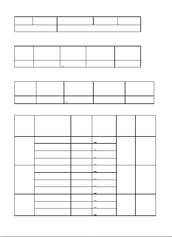
1-2 ElectricalSpecifications
Accuraciesarespecifiedinthe way:
±(…% of reading +…digits) at 23ºC±5ºC,below 80%RH.
OHMS
Range
Resolution
Accuracy
Max. open
Circuit Voltage
Overload
Protection
40.00Ω
0.01Ω
+(1.2%+3)
5.8V
250Vrms
400.0Ω
0.1Ω
5.8V
ContinuityBeeper
Range
Resolution
Operation
Resistance
Max.open
Circuit
Voltage
Overload
Protection
5
•)))
0.01Ω
Resistance≤35Ω
5.8V
250Vrms
Short circuit current
≧200mA
DC Voltage
Range
Resolution
Accuracy
Input
Impedance
Overload
Protection
1000V
1V
+(0.8%+3)
10MΩ
1000Vrms
ACVoltage (40Hz~400Hz)
Range
Resolution
Accuracy
Input
Impedance
Overload
Protection
750V
1V
+(1.2%+10)
10MΩ
750Vrms
Meg OHMS
Terminal
Voltage
Range
Resoluti
on
Accuracy
Test
Current
Short
circuit
current
125V(0
%~+10
%)
0.125~4.000 MΩ
0.001MΩ
+(2%+10)
1mA
@load
125kΩ
≤1mA
4.001~40.00 MΩ
0.01MΩ
+(2%+10)
40.01~400.0 MΩ
0.1MΩ
+(4%+5)
400.1~4000MΩ
1MΩ
+(5%+5)
250V
(0%~+1
0%)
0.250~4.000 MΩ
0.001MΩ
+(2%+10)
1mA
@load
250kΩ
≤1mA
4.001~40.00 MΩ
0.01MΩ
+(2%+10)
40.01~400.0 MΩ
0.1MΩ
+(3%+5)
400.1~4000MΩ
1MΩ
+(4%+5)
500V(0
%~+10
%)
0.500~4.000 MΩ
0.001MΩ
+(2%+10)
1mA
@load
500kΩ
≤1mA
4.001~40.00 MΩ
0.01MΩ
+(2%+10)
40.01~400.0 MΩ
0.1MΩ
+(2%+5)
6
400.1~4000MΩ
1MΩ
+(4%+5)
1000V
(0%~+1
0%)
1.000~4.000 MΩ
0.001MΩ
+(3%+10)
1mA
@load
1MΩ
≤1mA
4.001~40.00 MΩ
0.01MΩ
+(2%+10)
40.01~400.0 MΩ
0.1MΩ
+(2%+5)
400.1~4000MΩ
1MΩ
+(4%+5)
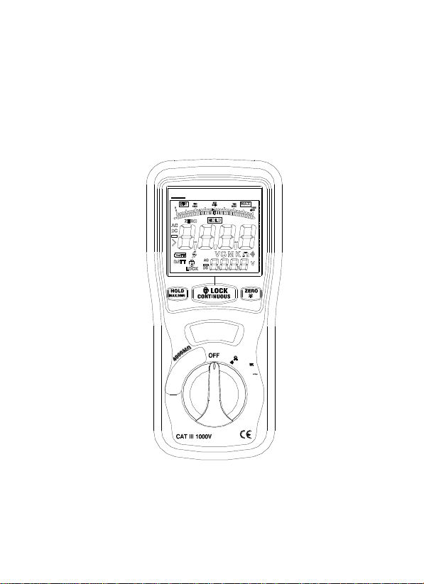
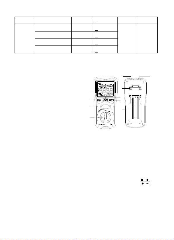
2. PARTS & CONTROLS
1.Digital Display
2.Data Hold Button; MAX/MIN
3.LockButton
4.Backlight Button; ZERO
5.TestButton
6.Rotary Function switch
7.VΩJack
8.COM input jack
9. Pothook
10.Battery Cover
2-1 How to connect test leads.
On MΩRange , and 400Ω/BZ ,ACV,.DCV, Connectthe red test
lead into the “VΩ” terminal and the black lead into the “COM”
terminal.
2-2BatteryCheck-UP&Replacement
a) As battery power is not sufficient. LCD will display .
Replacement of 6 pcs new batteries, type 1.5V size “AA” is
Required.
b).Place back thebattery cover andfour thescrews.
2-3 Test leadscheck
Set the range select switch to the 400Ωrange. With the tip and
750V
1000V
Insulation Tester
400
125V
250V
500V
1000V
TEST
LOBAT HV
(1) POL1
(2)
(1) OHM
BZ
(2)
(2)
POL2
4
(1)
BAR
1
85
1
23
4
6
78
9
10
CEM DT -5505
5

7
alligator clip of the test leads connected. The indicator should read
00.0Ω. When the leads are not connected the display will read
infinity indicated by “OL”. This w ill ensure that test lead are under
workingcondition.
2-4RotarySwitchpositions
Turn the Testeron by selecting any measurement
Lift <1000v,500v,250v,125v (4000MΩ)
OFF 400Ω/BZ,1000VDC,750VAC >Right
2-5 Buttons and a displayIndicators
a).Button
HOLD/MAX.MIN: Instant-pressingthe“HOLD”button the 1sttime,
the currentvalues willbe hold in the primary display.,but itwill return
in the 2nd pressing ; pressing 2seconds ,itwill enter directly into the
“MAX”status,andoneanother instant-pressingwillswitchtothe
“MIN”, if instant-pressingoncemore,it willrecycle,butexitif
pressing2 seconds again.
LOCK :In theinsulation resistance testingfunction,press the
“LOCK”button ,and then pushdown the“TEST”key, itw ill occur the
high-voltage andenter theinsulation resistance testingstatus. Press
the “TEST”button once more ,it willshutoff thehigh-voltageandexit
fromthe insulation resistancetestingstatus.
TEST : In theinsulation resistancetestingfunction,pressingand
holding the “TEST”button,The meter willbringhigh-voltage,and
enterinto the insulation resistancetesting,beingfreefromthe
“TEST”, it willcutoffthehigh-voltageandexitformtheinsulation
resistancetesting.
ZERO/LIGHT :Iinstant-pressingthe “ZERO/LIGHT”button in the 1st
time, the currentvalues inthe primary display w illbeset
zero,(mainly usedfor 400Ω,the low resistancetesting),,itwillreturn

8
if in the 2nd time. pressingfor 2 seconds, itwill enter directly into the
“LIGHT”status,and theLCD backlight light up.After 15seconds, the
backlight is shutoff automatically,the same as pressingfor2
seconds within15s.
b) Display Indicators
The Primary Display:Indicate the currentfunctiontestingvalues
The Secondary Display:It shows theoutput DCV whileyou test the
insulation resistance,and thebattery voltagewhiletheACV
The Analog Bar:indicate the current function testing value in
synchronous withthe primary display.
:While testing the insulation resistance, the symbol
““flashes frequently if thevoltageis over 30V.
•))) : While testing the insulation resistance, the symbol”•)))
“flashes frequently andthebuzzer warnscontinually if the
outsidevoltageis over 30V.the symbol“•))) “is indicated
whileLOΩ≤35Ωandthe BZ warnscontinuously.
LOCK:Push down the “LOCK”button while you test the insulation
resistanceandthesymbol “”is indicated.
LOBAT:The display shows “LOBAT”when the voltage
drops below 7.5V
MAX/MIN:Standforthemaximum or the minimum.
ZERO : Digital zeroadjusting。
HOLD :The digital holding functionfor theprimary display.
AC,DC,:Theindicatorfor thevoltageproperty.
V,MΩ,ΩThe measureddimension units。

9
3. INSULATION RESISTANCE MEASUREMENTS
a)Turn the function switch from the “OFF”position to the left(4000
MΩ/1000V---4000/ MΩ500V---4000 MΩ/250V---1000
MΩ/125V),andchose oneof thevoltage-block( thereare 4ranges
namely, 4 MΩ40 MΩ400 MΩ4000 MΩ, can be switched
automatically for every voltage-block.)
b)Connect twotestinglines to thetested;
c)Push down and hold the “TEST”button /or press the “LOCK”
keystoke first and then the “TEST”button, if the tested is
electriferous and its voltage ( AC/DC) is over 30V, it will refuse
work and no high-voltage testing occurs, simultaneity, it shows
“>30V”on the LCD, the symbol “”flashes, and the buzzer
warns frequently. if the tested is diselectriferous or its voltage is
lower than 30V, it will enter into the formal testing process and
brings the high-voltage. on the primary display, the insulation
resistance in MΩis indicated in-phase with analog bar; on the
secondary display, the tested insulation voltage in V (DC) is
indicated, the symbol “”flashes and the buzzer warns
frequently
d)Being free from the “TEST”button or pushing down the “TEST”
button in the “LOCK “status can exit fromthe “LOCK”status and
shutoff the high-voltage,synchronously, the resistance values is
indicated in the primary display will be held, and the secondary
display still be in the status of monitoring the insulation voltagefor
the tested.
e)Subsequently, discharge the balance insulation voltage of the
testedthroughthe inner switchof themeter.
Turning the function switch can exit automatically from testing
status duringthe process。

10
4.LOW RESISTANCE (CONTINUITY)
MEASUREMENTS
a).Set the rangeswitchto400Ω/BZ Position
b). Connect the red test lead to the V Ωterminal and black to the
COM terminal.
c). Connect the tips of the testleads toboth ends of thecircuit under
test. read resistance in Ωon the LCD. The two
ranges(40.00/400.0Ω) can be switched automatically; the
primary display of the resistance in Ω, flashes in synchronous
withtheanalog bar.
d). When the impedance on circuit is below approximately ≤35Ω.It
willindicate by a continuous beeper.
e) The current isfrom 200 to 220mA while the tested resistance is
0Ω
f) The high voltage symbol “ “flashes along with a primary
display of “>30V” and the buzzer warns frequently if the voltage
(AC/DC) is more than 30V.
5.AC/DC VOLTAGE MEASUREMENTS
a).Set the rangeswitchtoACV orDCV position
b). Connect red test lead to “V Ω” terminal and black test lead to
terminal “COM”.
c). Connect test prodsof test leadsIN PARALLEL to the circuit being
measured.
d).Read the voltagevalueon LCD.

11
6.BATTERY SAVER (SLEEP MODE)
The meter willautomatically enterthe “sleepmode”if there is no
functionchangeor buttonpress for 10minutes,but it w orks as soon
as youturn the rotary function switchor pushdownany button.
7.POWER TOOLS AND AMALL APPLIANCES
This testwould also apply to other similar equipment that has a line
cord. For double insulated power tools, the megohmmeter lead
shownconnected to the housingwould be connected to some metal
partlf thetool(e..g chuck,blade).
Note: The sw itch of the device must be in the “ON” position and the
main powershouldbedisconnected.
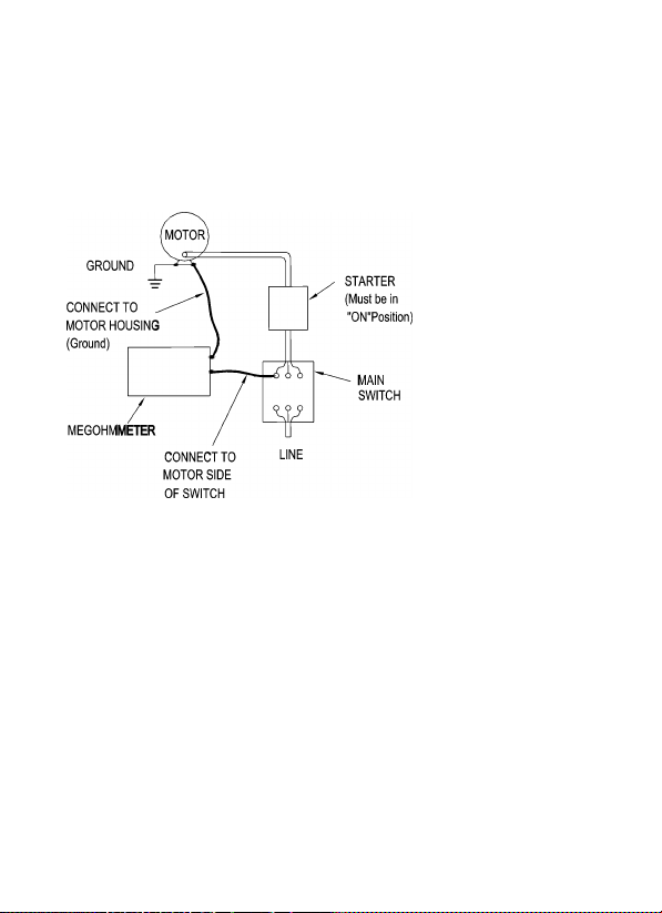
MOTORS
AC-Disconnect the motorfromthe line by disconnecting thewires at
the motor terminals or by opening themain sw itch. If the main switch
is used and the motor also has a starter then the starter must be
held, by some means, in the “ON” position. In the latter case, the
measured resistance will include the resistance of the motor, wire
and all other components between the motor and the main switch. If
a weakness is in dicated, the motor and other components should
be checked individually. If the motor is disconnected at the motor
terminals, connect one megohmmeter lead to the grounded motor
housing and the other lead to One of the motor leads.
DC-Disconnect the motor from the line. To test the brush rigging,
field coils and armature connect one megohmmeter lead to the
grounded motor housing and the other lead to the brush on the
commutator. If the resistance measurement indicates a weakness,
raise the brushes off the commutator and separately test the
12
armature, field coils and brush rigging by connecting one
megohmmeter lead to each of them individually, leaving the other
connected to the grounded motor housing. The above also applies
to DC Gemerators.
13
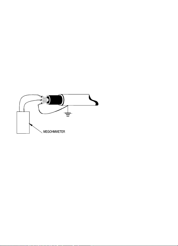
CABLES
Disconnect the cablefromthe line. Also disconnect opposite end to
avoid errors due to leakage from other equipment. Check each
conductor to ground and /or lead sheath by connecting one
megohmmeter lead to a ground and /or lead sheather and the other
megohmmeter lead to each of the conductors in turn. Check
insulation resistance between conductors by connecting
megohmmeter leads to conductors inpairs.
Table of contents
Other CEM Test Equipment manuals


Popular Test Equipment manuals by other brands

Huazheng
Huazheng HZ-4000T2 Guide

Helmut Singer Elektronik
Helmut Singer Elektronik 2467B manual

MULTI MEASURING INSTRUMENTS
MULTI MEASURING INSTRUMENTS 104 instruction manual

Zodiac
Zodiac PH Expert Instructions for installation and use

Keysight
Keysight N1000A DCA-X Series quick start guide

CIE
CIE 4871.MOT.V1 product manual


NDT Systems
NDT Systems Bondascope 350 Operator's manual

BGS technic
BGS technic 67241 instruction manual

Sperry instruments
Sperry instruments VT611 operating instructions

Teledyne Lecroy
Teledyne Lecroy Summit Gen4 Test Platform User manual and quick start guide

vinmetrica
vinmetrica Dissolved Oxygen System user manual

Huazheng
Huazheng HZ1731 user manual