CIE 4871.MOT.V1 User manual

Page | 1
4871.MOT.V1
MINING OUTLET TESTER
PATENT PENDING NO: AU2017902878
PRODUCT MANUAL

Page | 2
Contents
1. SAFETY MEASURE.................................................................3
2. FEATURES.............................................................................6
2.1 Instrument Layout....................................................6
2.2 Test Function............................................................7
2.3 Applied Standards....................................................8
2.4 Features & Specification ..........................................8
3. TESTING INSTRUCTIONS.....................................................10
3.1 EARTH LEAKAGE LOCKOUT TEST (ELL) ...................11
3.2 FROZEN CONTACT TEST (FC)..................................13
3.3 EARTH CONTINUITY (EC)........................................15
3.4 REMOTE START/STOP ............................................17
3.5 EARTH LEAKAGE TEST (EL) .....................................18
3.6 PHASE INFORMATION............................................22
4. SERVICING..........................................................................24

Page | 3
1. SAFETY MEASURE
This Instrument has been designed and tested according
to IEC 61010: Safety Requirements for Electronic
Measuring Apparatus. This instruction manual contains
safety rules and warnings which must be followed by
the user to ensure safe operation of the instrument and
safe working conditions. Read these instructions
carefully before using this instrument.
CONDTION OF USE:
This instrument must only be used by a competent and
trained person with adequate certification, such as a
licenced electrician. CIE will not accept liability for any
damage or injury caused by misuse or non-compliance
with the instructions. It is important to read and to
understand the safety rules contained in the instructions
provided.
DANGER is reserved for conditions and actions
that are likely to cause serious or fatal injury.
WARNING is reserved for conditions and
actions that can cause serious or fatal injury.
CAUTION is reserved for conditions and actions
that can cause a minor injury or instrument damage
Page | 4
DANGER
-This instrument is to be used only for intended
applications and under safe conditions,
otherwise safety functions of this equipment will
not work, and instrument damage or serious
personal injury may occur.
-When conducting tests do not touch any
exposed metalwork associated with the
installation. In certain tests this metalwork may
become live for the duration of test.
WARNING
-This instrument is to be used only for the
intended applications and in safe conditions.
-This instrument and testing must be performed
by trained professionals with appropriate
licences.
-Conduct all tests according to the safety
procedures provided by your workplace.
-Do not remove internal the sealed front cover
of the instrument - there are dangerous voltages
present and this may void the manufacturer
warranty.
-If a fault occurs with this instrument, return it to
your distributor for inspection and repair.
-If any abnormality such as a faulty display,
broken case, cracked screen etc. occurs with the

Page | 5
instrument do not use it and return it to your
distributor for repair.
-Never attempt to use this instrument in wet
conditions.
CAUTION
-For safety reasons only use accessories that are
designed to be used with this instrument and
recommended by CIE.
-Use a damp cloth and a mild detergent to clean
the instrument. Do not use abrasive materials or
solvents (eg. methylated spirits).

Page | 6
2. FEATURES
2.1 Instrument Layout
1……… Instrument On/Off
2……… Battery Voltage Indication
3……… Main Control Touch Screen LCD
4……… Battery Charging socket
5……… Earth Leakage Current Selector Switch (1000V
& 415V)
Page | 7
6……… Frozen Contact Voltage Potentiometer
7……… Frozen Contact Voltage Indicator
8……… RGB colour LED indicator light
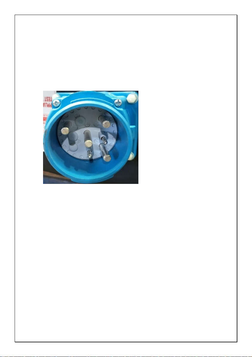
This instrument is
supplied with an
Appliance Inlet DS3
1000V 3PE&2Aux 32A,
where the test device
will connect via test
lead.
2.2 Test Function
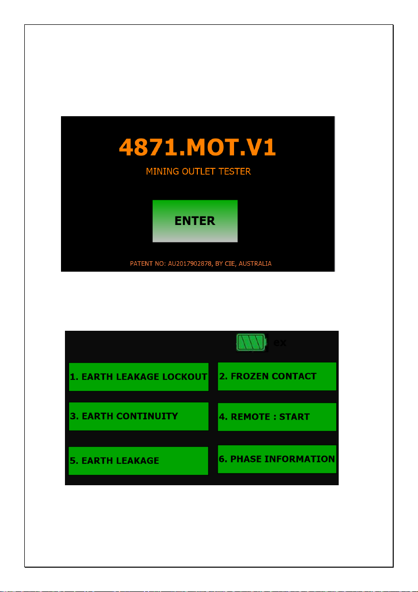
4871.MOT.V1 performs the following 6 test functions.
1. Earth Leakage Lockout
2. Frozen Contact
3. Earth Continuity
4. Remote Start and Stop
5. Earth leakage with trip time

Page | 8
6. Phase information
2.3 Applied Standards
Instrument operation: IEC 61557-1
Safety: IEC 61010-1, CAT III(1000V),
CAT IV 600V, IEC 60950
Protection degree: Operational IEC60529(IP54)
Instrument in Storage 0529(IP64)
2.4 Features & Specification
4871.MOT.V1 comprises the following features:
•High speed
•User friendly
•Touch screen operation for all tests
•Live battery voltage information
•Phase information
o Phase-Phase voltage, Phase-Earth voltage
o Phase Rotation, Phase status information
•Earth continuity, short circuit and open circuit
tests

Page | 9
•Frozen contactor tests
•Earth leakage lock out tests
•Earth leakage test with 1000V, 415/240 and
110V via variety of different current levels.
•Enclosed in a sturdy carry case for enhanced
portability and durability
•Light weight and long battery life for continuous
operation (5 hour+)
•Size: 387 x 394 x 260 mm
•Weight: <9.5 kg including accessories
•Patented Design
Page | 10
3. TESTING INSTRUCTIONS
PRESS ENTER TO PROCEED TO MAIN TEST SCREEN
Main Test Screen (Main Menu)

Page | 11
3.1 EARTH LEAKAGE LOCKOUT TEST (ELL)
PRESS this button to enter Earth Leakage Lockout
-Select your Pilot Mode according to the
switchboard setup. Select Phase for ELL test

Page | 12
Earth Leakage Lockout Main test screen
-From above test screen user can choose three
different resistor values under selected phase to
conduct the ELL test.
-This shows ELL test is On and also will display
selected resistance and phase. In 9K and 900K
continuity will be made healthy. Attempt to close
the contactor to prove the ELL relay is stopping
the contactor from closing. Continuity is not
made healthy in 3.3M.
Page | 13
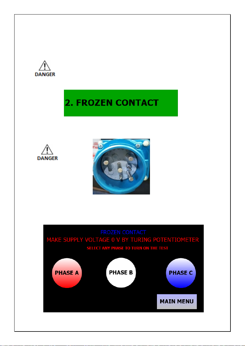
3.2 FROZEN CONTACT TEST (FC)
DO NOT ENTER THIS TEST UNTIL THE TEST LEAD IS
CONNECTED TO THE MOT AND THE OUTLET TO BE
TESTED, AS THE MOT’S MARECHAL INLET WILL BE
ENERGISED DURING THIS TEST.
PRESS this button to enter the FC test screen
DANGER INLET PINS ARE NOW LIVE
-After entering test Voltmeter and Potentiometer
will activate for testing.
-Select a phase.
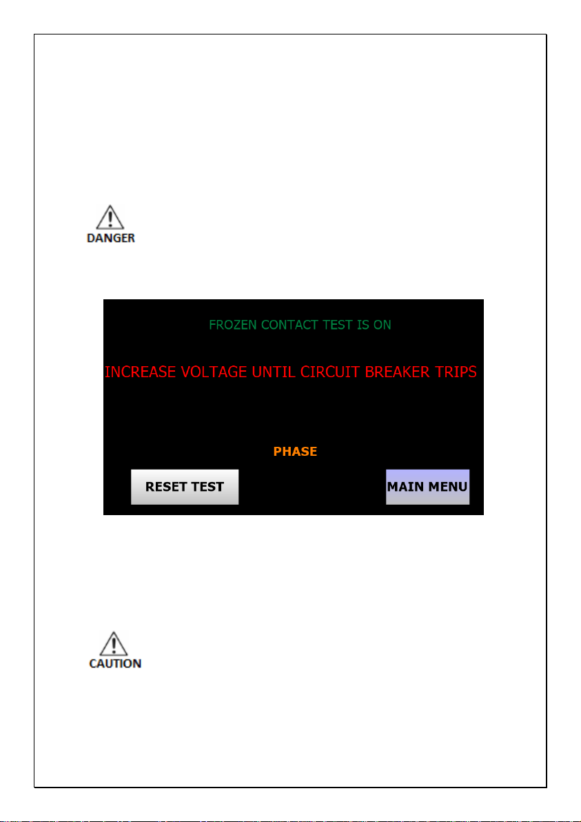
Page | 14
-Potentiometer will allow the user to select test
voltage from 0 to 120 VAC which will show on
the voltmeter. Turn voltage to 0 Volts and select
a Phase.
-This test is live and will inject up to 120VAC.
All workplace safety procedures should follow
during this test.
-Increase the voltage slowly around 3 volts per
second until circuit breaker trips
-Press Reset Test to reset the test and select
different Phase.
-After completing test return Frozen Contact
Voltage Potentiometer to Zero
-Press MAIN MENU to terminate FC test and go
back to main test screen.

Page | 15
3.3 EARTH CONTINUITY (EC)
Press this button to enter Earth continuity
-Select your Pilot Mode according to the
switchboard setup.

Page | 16
Earth Continuity Test Screen
-Press Healthy to activate then press Open for
Open Earth continuity test
-Press Healthy to rest then press short for Short
Earth continuity test
-To exit test, press MAIN MENU

Page | 17
3.4 REMOTE START/STOP
PRESS this button to enter remote start
-Select your Pilot Mode according to the
switchboard setup. Please note IPM relays do
not support remote start in diode mode.
-Wait for Earth continuity/RTM to be healthy then
Press start, wait for contactor to close then press
Stop.

Page | 18
3.5 EARTH LEAKAGE TEST (EL)
PRESS this button to enter Earth Leakage test
-When conducting tests do not touch any
exposed metalwork associated with the
installation. In certain tests this metalwork may
become live for the duration of test.
-Select remote or local start.

Page | 19
-Select earth continuity from Diode or RTM (refer
to board manufacture), if there is no earth
continuity, select Diode.
Remote Local
-Close the contactor to energise the outlet under
test.
Earth Leakage phase selection test screen

Page | 20
-Select only one current level. Incorrect selection
can cause variation in trip time. Check correct
voltage is selected.
-Check current and voltage for EL test before
pressing enter to start the test.
-Once test finishes trip time will display in
milliseconds.
Table of contents
Popular Test Equipment manuals by other brands


iPA
iPA ALPHA MUTT manual

OSTBERG
OSTBERG HERU S Series installation instructions

Lifebreath
Lifebreath Pure Performance 30ERV installation manual

Kikusui
Kikusui HP21-TOS Operation manual

KAPSCH
KAPSCH T600 Operator and maintenance manual

Thermo Scientific
Thermo Scientific Thermolyne NCAT F85930-33 Installation and operation manual


