NDT Systems Bondascope 350 User manual

Bondascope 350 Operator's Manual


Bondascope 350 Operator's Manual
1 INTRODUCTION ..................................................................................................................................... 1
1.1 IMPORTANT: ................................................................................................................................... 1
1.2 General Features: ............................................................................................................................... 1
2 AREAS OF APPLICATION ..................................................................................................................... 2
3 PRINCIPLE OF OPERATION.................................................................................................................. 3
3.1 Resonance: ......................................................................................................................................... 3
3.2 Pitch-Catch:........................................................................................................................................ 3
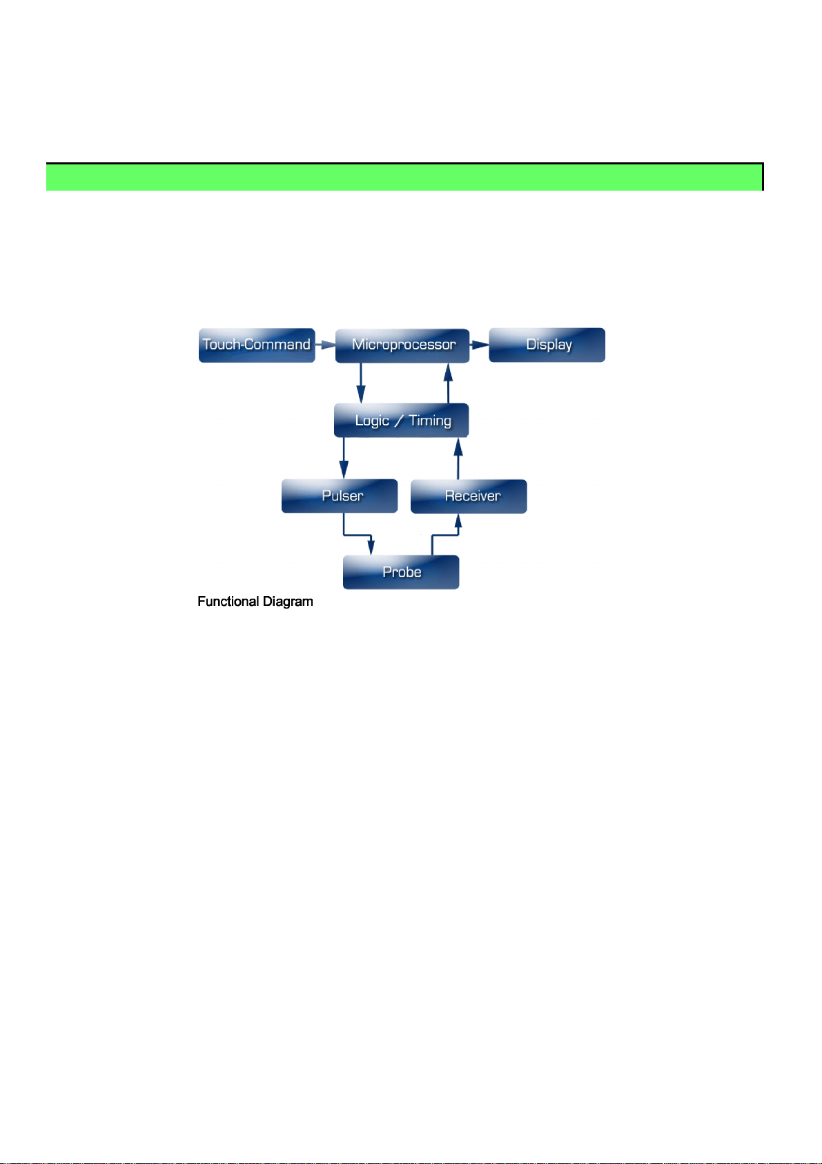
4 4.0 BASIC DESIGN .................................................................................................................................. 4
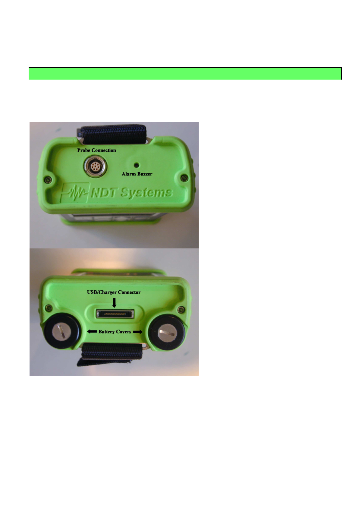
5 Description of Connections........................................................................................................................ 5
6 PREPARATION FOR USE....................................................................................................................... 6
6.1 Batteries: ............................................................................................................................................ 6
6.2 Probe Selection : ................................................................................................................................ 7
6.3 Reference Samples - IMPORTANT!!................................................................................................ 7
7 KEYPAD AND OPERATION.................................................................................................................. 8
7.1 ON/OFF COMMAND....................................................................................................................... 8
7.2 SETUP ............................................................................................................................................... 8
7.3 GAIN.................................................................................................................................................. 8
7.4 MENU/ESC BUTTON ...................................................................................................................... 8
7.5 LEFT, RIGHT, UP, DOWN ARROW and ENTER Keys................................................................. 8
7.6 NULL – Also acts as a BALANCING function where required ....................................................... 8
7.7 PROFILE ........................................................................................................................................... 9
7.8 Alarm Key.......................................................................................................................................... 9
7.9 MODE Keys (RF/DOTS, SWEEP & GATES) ................................................................................. 9
7.9.1 RF / DOTS Key.............................................................................................................................. 9
7.9.2 SWEEP Key................................................................................................................................... 9
7.9.3 GATES Key................................................................................................................................... 9
8 MAIN SCREEN & MENU Items............................................................................................................ 11
8.1 Main Menu Screen........................................................................................................................... 11
8.2 MAIN MENU ITEM DESCRIPTION ............................................................................................ 12
8.2.1 Gain.............................................................................................................................................. 12
8.2.2 RNG – RANGE ........................................................................................................................... 12
8.2.3 DLY – DELAY............................................................................................................................ 12
8.2.4 VLTS - VOLTS ........................................................................................................................... 12
8.2.5 GATE........................................................................................................................................... 12
8.2.6 FREQ – FREQUENCY ............................................................................................................... 12
8.2.7 PRB – PROBE ............................................................................................................................. 12
8.2.8 CYCLES ...................................................................................................................................... 12
8.2.9 DISP............................................................................................................................................. 13
8.2.10 ALRM – ALARM........................................................................................................................ 13
8.2.11 SET - SETUP............................................................................................................................... 14
8.2.12 SCRN - SCREEN SAVE............................................................................................................. 14
8.3 MAIN MENU ITEM OPERATION................................................................................................ 15
8.3.1 DOTS ........................................................................................................................................... 15
8.3.2 FREQ - FREQUENCY................................................................................................................ 15
8.3.3 ROT – ROTATE.......................................................................................................................... 15
8.3.4 POS - Position.............................................................................................................................. 16
8.3.5 Xscl – X Scale Factor................................................................................................................... 16
8.3.6 Yscl – Y Scale Factor................................................................................................................... 16

8.3.7 PRB – Probe..................................................................................................................................16
8.3.8 PERS – Persistence.......................................................................................................................16
8.3.9 VLTS – Volts................................................................................................................................16
8.3.10 SET – Setup ..................................................................................................................................16
9 9.0 Front Panel Keys.................................................................................................................................17
9.1 PROFILE - Bond Profile Front Panel Key.......................................................................................17
9.2 SETUP ..............................................................................................................................................17
9.3 GAIN.................................................................................................................................................17
9.4 ALARM............................................................................................................................................17
9.5 NULL................................................................................................................................................17
10 INSPECTION TIPS & TECHNIQUES................................................................................................18
10.1 Resonance Sample Setup Procedure.................................................................................................18
10.2 PITCH-CATCH Sample Setup Procedure........................................................................................19
10.3 Care and use of Pitch-Catch Probes..................................................................................................19
10.4 Amplitude Inspection........................................................................................................................20
10.5 Phase Inspection................................................................................................................................20
10.6 Signature Mode.................................................................................................................................20
10.7 Excessive Surface Roughness:..........................................................................................................20
10.8 Compound Contours:........................................................................................................................20
10.9 Non-Parallel Surfaces: ......................................................................................................................20
10.10 Material Temperature Effects:......................................................................................................21
10.11 Excessively Attenuative Materials:...............................................................................................21
10.12 Honeycomb Cell Shape on Directionality Effects:.......................................................................21
11 BondaScope Series - Features, Options, Probes and Accessories........................................................22
12 SPECIFICATIONS:..............................................................................................................................25
13 PRODUCT WARRANTY....................................................................................................................27

Bondascope 350 Operator's Manual
1
1 INTRODUCTION
All of us at NDT Systems, Inc. would like to thank you for your purchase of the BondaScope 350, Ultrasonic Bond
Tester, an instrument that not only provides the best value and feature set currently available but will also provide you
with many years of dependable performance.
The BondaScope 350 features the following:
•Membrane-sealed TOUCH-COMMAND control to simplify its setup and use.
•5.7", 240 x 320 Pixel, high contrast, graphic Liquid Crystal Display (LCD) allows for simple, plain text menus.
•Variable Frequency, and Cycle Tone Burst Oscillator.
•Resonance & Pitch-Catch Mode along with Pulsed Mode for Broader Banded Probe Response.
•Ultra-portability available in a hand-held instrument incorporating NDT Systems’ “Easy Grip” Custom Extruded
Aluminum Case.
•State-of-the-Art RISC based Microprocessor-based design offers unparalleled performance for Bonding
applications.
•Exclusive ScanBars feature permits a simple, analog metered display of Amplitude and/or Phase for easy &
rapid view of bond trend.
•Scrolling ‘BPM’ (Bond Profile Mode) Scan - Standard. - Industry First in a bond tester
•Auto Probe Recognition (patented)
•Fully Adjustable Range - Standard
•Waveform Storage for up to 250 Screen sets along with their associated setups.
•3 Default User Modes / Probe - Standard
•Alarm Limits in high speed scan mode.
•Alarm LED on Instrument & Probes
•USB Data Transfer Port permits upload of user setups & download of User Setups and stored screen
information.
•Operates on 6 “AA” NiMh Batteries for up to 8 hours of continuous use.
•1.8 lbs with batteries.
•Variety of Probes available to suit a range of applications.
1.1 IMPORTANT:
The BondaScope 350's unique design makes it one of the most portable and simple to operate Bond Testers available.
However, in order for the owner of this advanced technology instrument to fully benefit from the unique features of the
BondaScope 350, the assigned operator(s) must be experienced and well-founded in the fundamentals of ultrasonic
testing. Also, it is highly recommended the operator be familiar with this manual.
When using the Bondascope series instruments always be sure the cables are in good working order and be sure to
use cables no longer than necessary. Reduced performance and higher signal to noise ratios can be expected with
cables longer than necessary.
1.2 General Features:
The BondaScope 300 & 350 are designed as portable and robust instruments provided in an aluminum extruded case
with high impact plastic cover plates. The handle assembly is operated by loosening the knobs and pulling outward on
the handle arms to disengage them from the indexing pins and rotate to the desired position. Re-engage the indexing
pins and tighten the handle knobs.

Bondascope 350 Operator's Manual
2
2 AREAS OF APPLICATION
The BondaScope 350 inspects a wide range of Bonded on metals, plastics, ceramics, glass or virtually any other
material which will satisfactorily conduct ultrasound, and has fairly parallel (or concentric) surfaces. The actual range is
material and application dependent.
The durable custom extruded, design allows the unit to withstand the rigors of heavier industrial environments.
The All New BondaScope Series defines a new standard in ease of use, performance, features and portability in a
Portable, Handheld Bond Tester. The ALL NEW BondaScope 350 operates in Continuous Wave, Tone Burst or Pulsed
mode (depending on user application & probe selected) as well as Pulsed Pitch-Catch mode with Pulse Rates up to
300 Hz. Display Updates of 40+Hz. With the introduction of NEW, industry leading features including SplitView and
SplitScan the BondaScope 350 presents the best indication and presentation of potential bond problems available
today. NDT Systems, Inc. is unique in offering, for the first time in industry, the ability to scan a surface and map a
Bond Profile in real time! This mode can be significantly easier to interpret for users of all levels. Other,
SIGNIFICANTLY more expensive units may offer to store a TOTAL of a mere 20 waveforms; the BondaScope can
store over 250 full scan sets!!
The concept of Scanning and presenting historic information on screen, in real time, allows the operator to assess the
pattern over distance and/or time, thereby developing a trend pattern. This information can provide the operator with a
higher level of confidence.
Setup is as simple as setting a probe over a good area and pressing NULL, then go over a bad area, set gain and/or
alarm level threshold.
The high speed (120Hz refresh rate), sunlight readable display offers a full Quarter VGA resolution. The resolution of
the display will appear to approach analog! User interface is via simple plain text menus located at the bottom of the
display.
Examples subjects of evaluation:
Airframes/Aircraft Skins
Bulkheads
Crushed Core
Fiberglass
Adhesive Joints
Cardboard
Skin to Honeycomb
Skin to Skin Composite to Aluminum Honeycomb
Multi-Layer Aluminum Laminates
.... And More

Bondascope 350 Operator's Manual
3
3 PRINCIPLE OF OPERATION
The BondaScope 350 operates on a principle similar to sonar, operating in frequency ranges of 1 KHz to 1MHz
3.1 Resonance:
Resonance inspection is typically performed by inducing a continuous wave, fixed frequency to a vey narrow banded
probe or sensor head. When the probe is coupled to the sample under test, the acoustic impedance change within the
material (due to unbounded or other conditions) loads the probe in a manner to affect its resonant frequency and
amplitude.
3.2 Pitch-Catch:
The following figure explains the ultrasonic Pitch-Catch principle that the BondaScope 350 and its dual tip probe
(transducer) employ. The probe's transmitter element (T) sends a short ultrasonic tone burst or pulse into the material.
The burst or pulse traverses the surface of the material under test to the receiver tip. The frequency selected to
provide the maximum flexural motion in the top layer thickness in the material under test. A variable time gate is used
to select the position in the received echo envelope which has the greatest change in amplitude and or Phase when
the probe is scanned from a bonded area to an un-bonded area.
This round trip time is correlated to the material's thickness (i.e.. the thicker the material, the longer the round trip
time). By precisely measuring the round trip time and compensating for the characteristic ultrasonic velocity of the
material being gaged (sound velocity differs in various materials), an accurate thickness indication can be obtained.

Bondascope 350 Operator's Manual
4
4 4.0 BASIC DESIGN
The BondaScope 350 incorporates the latest technology available in microprocessor design. Through sophisticated
on-chip programming, the RISC based microprocessor computes, transit time from one tip to the other, and directs
numerous operations at high speeds. It also offers simplified setup and operation (gage calibration) via front panel
TOUCH-COMMAND pushbuttons.
The Continuous Wave, Tone Burst or Pulsed transmitter, high-sensitivity receiver and informative digital display
function in concert with the microprocessor to produce the unparalleled performance and ease of use in determining
potential bond integrity.

Bondascope 350 Operator's Manual
5
5 Description of Connections
1) Probe Connection - 8 pin – Connector for BondaScope 300 & 350 Probes
2) USB/Charger connector on bottom panel. (BE SURE TO LOAD USB DRIVER PER INSTRUCTIONS BEFORE
CONNECTING INSTRUMENT TO A PC)
3) Two battery covers (6 AA batteries 3 in each tube).

Bondascope 350 Operator's Manual
6
6 PREPARATION FOR USE
6.1 Batteries:
The BondaScope 350 comes with six “AA” NiMH batteries installed 3 in each battery tube. The batteries supplied with
the unit are 2700 mAh Sanyo’s, the 350 will run approx 8 hours with the backlight off.
When the batteries are within the instrument, check for satisfactory battery life by pressing press the ON/OFF touch
command to turn power on. A Battery Icon appears on the upper right side of the display indicating the current battery
charge state. If the display readout fails to register more than 20% scale the batteries will need charging. When power
becomes marginal, the Power-Guard Marginal Cutoff feature automatically turns the power off until the batteries are
charged or replaced.
Battery Replacement:
Loosen (counterclockwise) the battery tube covers on the bottom plate of the instrument with a screwdriver or a coin.
Remove the batteries and replace with another full set.
Often NiMH batteries that are not charging correctly in the instrument can be reconditioned in an external charger that
is setup for reconditioning and be returned to service.
CAUTION:
Charging:
USE ONLY NDT Systems supplied charger. Plug the charger into wall and then into instrument. The “Charging”
indicator will usually glow green for a second while the charge circuit determines the current state of charge and then
turns RED to indicate a status of charging. When charge is complete, the indicator will return to GREEN.
While the 350 will run off of any AA batteries. ONLY USE THE CHARGER IF EITHER THERE ARE NO BATTERIES
INSTALLED OR NIMH BATTERIES ARE INSTALLED. If Alkaline, NiCd, or any other chemistry batteries are installed
and the charger plugged in damage may occur to the instrument.
NOTE: It is normal for the instrument to warm slightly while charging.
“An optional, conditioning external charger is also available for charging an extra pack while or
conditioning/recalibrating a Li-Ion pack.”
Charge while operating is supported from any charge level.

Bondascope 350 Operator's Manual
7
6.2 Probe Selection :
Many probes are available supporting all test modes of the BondaScope 350 to optimize performance for the broad
spectrum of inspection applications that may be encountered. The BondaScope 350 will automatically identify an
attached NDT Systems, Inc. probe. Use of a particular probe for a given application is at the discretion of the user.
Generally selecting a probe which permits the greatest amount of change on screen is an ideal candidate. Remember,
NO couplant is required in the Pitch-Catch mode but is required in the resonance mode for the BondaScope to
function.
6.3 Reference Samples - IMPORTANT!!
In order to use the BondaScope 350, or any other ultrasonic instrument for that matter, Reference Samples /
Standards are essential. At the very least, when setting the BondaScope 350 for use, the user should have an idea of
what is expected as a good area on the part under inspection and compare this area with an area suspected as bad.
Bond testing is a comparative test method.
Reference Samples can be anything from specifically designed and manufactured “Standards” to samples acquired
from known representative sources. Some of the samples in the picture below represent a cross section of various
types.

Bondascope 350 Operator's Manual
8
7 KEYPAD AND OPERATION
7.1 ON/OFF COMMAND
Turn on the BondaScope 350 by momentarily pressing the ON/OFF key. Once the power is on and no buttons are
depressed, the display will display NDT Systems, Inc Logo, Instrument type, & Software revision information. If no
probe is attached the main screen will indicate so and go no further as shown in the image below on the left.
Once a probe is connected a screen similar to the one on the right is displayed offering the user the option of selecting
the default startup setting or recall a previously stored setup. The default setting is generally acceptable, as is, for a
starting point in inspection. In the example the PCL series probe is selected and we have selected the default setting.
7.2 SETUP
The SETUP key provides a direct access method to the setup/recall menu for quick recall of user stored setups.
7.3 GAIN
The gain up and down keys are direct access keys to simplify setup as GAIN will likely be the most used key along
with NULL.
7.4 MENU/ESC BUTTON
The MENU/ESC key is used to back out of a menu item below the main menu. For instance, ALRM menu item goes to
another menu. When complete, press MENU/ESC to return to the main menu.
7.5 LEFT, RIGHT, UP, DOWN ARROW and ENTER Keys
These keys help navigate the menu(s) as well as act on specific menu items. acts primarily as a shortcut key to the
DISPLAY menu for rapid adjustment of the Scan Bar if desired. In several menus the LEFT ARROW acts to decrease
associated menu values. To act on a menu item, highlight it and press ENTER. When finished, press MENU/ESC to
return to the main menu.
7.6 NULL – Also acts as a BALANCING function where required
NULL sets a relative data value to the baseline or zero in both X & Y. Generally the NULL function is used in Phase
mode to set a relative phase angle to zero. Example of use would be to place probe on a known good sample and
press NULL. Any deviation from the NULL will appear as a positive deflection.

Bondascope 350 Operator's Manual
9
7.7 PROFILE
Bond Profile is a new and unique mode to assist the user in identifying potential delaminations. In the image to the
right the BondaScope is set up to measure Phase and the surface of a composite to core is scanned for skin to core
delamination. Any level which exceeds the threshold will trigger the alarm light on the instrument and probe.
7.8 Alarm Key
The alarm key is a direct access to the alarm/ Beeper menu. It toggles the beeper on or off.
7.9 MODE Keys (RF/DOTS, SWEEP & GATES)
7.9.1 RF / DOTS Key
Toggles an impedance display or, when pressed a second time, an RF view of the currently attached probe. If a
resonance probe is attached a Continuous Wave (CW) representation will be displayed. If a Pitch-Catch probe is
attached, a Tone Burst will be displayed in the RF mode.
7.9.2 SWEEP Key
The SWEEP function provides a means to BALANCE the attached transducer/instrument combination as well as the
setting the Start and Stop frequency range.
7.9.3 GATES Key
Mode dependant. Acts as a hot key to the appropriate gate menu.
Balancing automatically sets optimal internal parameters to maximize amplification and scaling values to best match
probe, instrument and material under test.
In resonance, when a probe attached and default parameters are selected the BondaScope 350 will auto Balance and
bring the user to the sweep screen to accept or adjust otherwise.

Bondascope 350 Operator's Manual
10
The image to the right is an example of a 330KHz probe running uncoupled in air from 300KHz to 360KHz. Though
sweeping in a “resonant” mode seems counter intuitive, various samples tested exhibited a more dynamic screen
presentation when presented with various defects which, generally alerts the user in a very visual manner. Generally,
this mode of scanning is not very quantitative but rather, is useful for quickly locating areas of unbond to be further
interrogated in a conventional impedance plane mode as shown here.

Bondascope 350 Operator's Manual
11
8 MAIN SCREEN & MENU Items
8.1 Main Menu Screen
From the main menu place the cursor over a desired icon and press the ENTER key.
Note: the MAIN menu may also be reached by pressing the MENU/ESC button on the front panel or by pressing and
holding the knob depressed for 2 seconds.
The Menus in the BondaScope 350 are context or mode sensitive. For instance, if the unit is in the RF mode, (as with
the pitch catch mode) the display will take on the characteristics of the mode. If in impedance, then the appropriate
menus will be displayed.
When the unit is first turned on, the following is displayed if a probe is connected (This
image shows an L3330 Resonance Probe is connected as an example):
The probe connected and frequency as well as battery charge indicator. If no battery were
present and unit was running on charger, the battery icon will display AC in its icon
The next line identifies which mode and setup parameter (default or user setup) the
BondaScope is currently operating in.
The third line identifies the BondaScope is operating in Resonance, Pitch-Catch or MIA
The two sets of numbers over the waveform display indicate the range start and stop or the
X-Scale and Y-Scale values if in the impedance plane mode.
The waveform display may have the following features Vertical Gate Line, Dotted horizontal threshold limits - positive
and negative and the waveform itself. Note one of the cycles on the waveform in filled in. This is the actual cycle the
BondaScope is working with.
If the impedance plane mode is active, a cross hair will be displayed with an “N” at the cross points.
The next item below the waveform display are Level Bars (if in the RF mode), indicating the amplitude and phase level
off the NULL position. The vertical lines in the bars are the individual amplitude and phase alarm threshold levels. If in
the impedance mode, menu items will be displayed.
There will be a dot to the right of the scan bars as an indication that the specific phase or amplitude alarm is ON. If the
threshold were not triggered it would be just a dot to indicate the alarm is active. The square around the dot indicates
the amplitude alarm is in a triggered condition. The phase alarm is currently turned off in this example.
The following line is the active menu item selected. If RNG (range) were selected that line would indicate “Range :
XXX” where XXX is the current value of range.

Bondascope 350 Operator's Manual
12
8.2 MAIN MENU ITEM DESCRIPTION
If in Pitch-Catch, RF or TONEBURST Mode
8.2.1 Gain
Gain can be changed via this menu item or the Direct Access Keys. As a matter of
convenience, the GAIN Direct Access Key can be used while in any other menu item
without re-scrolling through the menu to return to a previous position. The knob can
also be used.
8.2.2 RNG – RANGE
Selects the value of the total screen range. Start and stop values are displayed over
the waveform.
8.2.3 DLY – DELAY
This is the screen Delay or waveform position within the window
8.2.4 VLTS - VOLTS
Sets the desired drive voltage. Upper limit of voltage drive is determined by the probe attached.
8.2.5 GATE
Select GATE, Press ENTER to select & use the Up or Down Arrow Keys to select the cycle in the received signal
envelope. This will be the position the Phase measurements are taken and NULL(ed) from.
8.2.6 FREQ – FREQUENCY
Frequency is available only when the Tone Burst probes are attached and is not available when the LOW Frequency
(High Power) or broader banded probe is installed. To optimize the frequency to be used with a given material, place
probe on a good surface of the material under test and adjust the frequency up or down to attain a maximum amplitude
response. This will vary slightly for various materials, thicknesses and geometry. Generally speaking though, the
default value may work just fine.
Next Menu line down
8.2.7 PRB – PROBE
Returns to the power on screen to select another probe or setup. If in the top most menu item “AUTO” simply plugging
in a new (NDT Systems) probe will identify and select the attached probe. The selection options are then DEFAULT or
LAST. The BondaScope 350 keeps track of the last probe type connected in association with that probe type. It dos
not keep track of the specific serial number attached to the probe. So, for instance, if a probe model number PCHS31
were connected, removed and another PCHS31 were attached, the setup could be selected but due to minor
variances in the probe, slight adjustments may be required.
8.2.8 CYCLES
The number of cycles driving the probe in the Tone Burst Pulser. Set Cycles to optimize received signal envelope
symmetry and amplitude.

Bondascope 350 Operator's Manual
13
Cycles is available only when tone burst style probes are connected. Pulsed Pitch-Catch probes will not offer this
selection.
8.2.9 DISP
8.2.9 DISP
Display Menu. When selected, press enter which opens to a new menu and permits the adjustment of baseline
OFFSet and the screen FREEZE and GRID feature.
8.2.9.1 FREEZE
The screen freeze feature allows the operator to press freeze which will allow the possibility to save the frozen
screen to memory for later transfer (with optional transfer cable and software)
8.2.9.2 OFFS – Offset
Permits changing the vertical position of the baseline
8.2.9.3 – GRID
Turns the screen reference grid on and off
8.2.10 ALRM – ALARM
When highlighted, press ENTER to display Alarm Menu (as illustrate to the right). Functions in this menu are as
follows:
8.2.10.1 - BUZZ - On or Off
8.2.10.2 - NO-SIG - Alarms on loss of signal - Signal
below threshold(s)
8.2.10.3 - AMP - Amplitude Alarm - On or Off
8.2.10.4 - Phase - Phase Alarm - On or Off
8.2.10.5 - AMP-THRESH - Sets the threshold level
the amplitude alarm triggers
8.2.10.6 - PHASE-THRESH - Sets the Phase
Degree change before alarm condition met. Default is 90 Degrees from NULL value.
Remember, Both amplitude and phase or any combination can be set. If material and unbond is particularly sensitive
to amplitude there would be no reason to select Phase as well. The reverse may be true regarding Phase.

Bondascope 350 Operator's Manual
14
8.2.11 SET - SETUP
This is where the operator saves customized setups. One normally starts with one of the default setups and modifies it
to suit a particular application. The user is offered up to 30 characters to name a file. In addition there are 8 lines of
comments available each offering 30 characters. These memos are saved with the setup. In this regard, the inspection
designer can name and comment the purpose of the inspection and or mention specific areas of interest during an
inspection as an example. The following illustrates the SETUP saving options.
From the MAIN MENU Screen press ENTER on SETUP Menu Item. From this menu the user can SELect a previously
saved setup or elect to SAVE a new one. If the user elects to load a previous setup, press SEL and select from the list
of previous saved files. If the user elects to save a new setup select SAVE and move to the next menu (figure)
From the SAVE - EDIT menu the user can select to save their custom inspection parameter. You can save with the
default name presented i.e. USER#3 alone or further edit the name. See the next illustration
When EDIT is selected from the previous screen, the user is presented with this menu to allow full QWERTY keyboard
style text editing for both file name and additional comments. When complete, press MENU/ESC to return to the
previous
screen above and press SAVE or CLR-TXT should you decide the default name is sufficient.
8.2.12 SCRN - SCREEN SAVE
Screen Save follows the same convention and options as the SETUP save and recall feature. Please refer to section
8. 1.10

Bondascope 350 Operator's Manual
15
8.3 MAIN MENU ITEM OPERATION
If in Impedance Plane-Resonance Mode
8.3.1 DOTS
•Dots selects a sub menu where screen position is stored for up to 8 places. A
ring, square or elliptical gate can then be set, sized and an alarm can be
activated for that gate. The following are the sub gate functions
•DOT# - Activates a specific dot to work on when multiple dots have been set
on screen.
•STORE – Sets the current flaw screen position when pressed and identifies it
by applying a number to the location. Once set, the DOT# will auto increment
to DOT#2 and so on.
•ERASE – Erases the selected DOT#. Renumbers any dot over the number
selected if they exist.
• GATE – Selects gate type. Either RECT, ELIPSE or OFF
•WID – Gate Width. Makes the gate wider or narrower.
•HT – Gate Height. Increases or decreases gate height.
NOTE: A relative number is displayed in the status line below the active screen to aid is setup. A square gate would be had by selecting equal WID
& HT
NEXT ROW
•X – Manually sets the X or horizontal position of the selected DOT#
•Y – Manually set the Y or vertical position of the selected DOT#
•ANGLE – Sets the DOT’s angle
•ALM – Sets alarm trigger to either IN or OUT of the selected gate geometry
•BUZZ – Turns the Audible alarm ON or OFF
•CLEAR – Clears ALL Reference DOTS from the screen to start over.
•ROT – Rotates the screen with the DOTS following in tact to allow for optimal positioning of DOT geometry
with reference to screen location
· In this image example, the screen has the same stored dot positions as “Resonance 1 - Dot Screen” except the
screen has been optimized to allow for increase in scale by repositioning the NULL
cross hair to a more lower left position. The SCALE could then be increased and, one
of the GATES was set to elliptical. These functions are generally not offered in
competitive instruments.
8.3.2 FREQ - FREQUENCY
Permits manual adjustment of frequency. Nominal frequency is set when probe is
attached. Balanced Frequency is set at any user selected balance interval.
8.3.3 ROT – ROTATE
Rotates the screen with the DOTS following in tact to allow for optimal positioning of DOT
geometry with reference to screen location
1
Resonance MAIN MENU Screen

Bondascope 350 Operator's Manual
16
8.3.4 POS - Position
Sets the crosshair Null point to any desired position on screen. This is useful if all impedance plane action in within on
quadrant for instance. In this case the screen can be rescaled to maximize the separation
between dots.
8.3.5 Xscl – X Scale Factor
Permits scaling of the X axis independent of the Y axis
8.3.6 Yscl – Y Scale Factor
Permits scaling of the Y axis independent of the X axis.
8.3.7 PRB – Probe
Returns to the power on screen to select another probe or setup. If in the top most menu item “AUTO” simply plugging
in a new (NDT Systems) probe will identify and select the attached probe. The selection options are then DEFAULT or
LAST. The BondaScope 350 keeps track of the last probe type connected in association with that probe type. It dos
not keep track of the specific serial number attached to the probe. So, for instance, if a probe model number PCHS31
were connected, removed and another PCHS31 were attached, the setup could be selected but due to minor
variances in the probe, slight adjustments may be required.
8.3.8 PERS – Persistence
Sets a form of Digital Persistence to keep dot path illuminated for easier visual tracing of dot path. Options are LOW –
Short duration, MED – Medium Duration, HI & CLEAR. When on HI the screen does not erase path lines until manually
cleared
8.3.9 VLTS – Volts
Adjusts probe drive voltage
8.3.10 SET – Setup
Refer to 8.2.10 for detailed instruction
2Sample Setup Configuration
Table of contents
Other NDT Systems Test Equipment manuals
Popular Test Equipment manuals by other brands

Agilent Technologies
Agilent Technologies InfiniiVision 6000 Series user guide

Tektronix
Tektronix 2445 instruction manual

Proceq
Proceq N / L operating instructions

Otto Bock
Otto Bock 757T16 Instructions for use

Renesas
Renesas EK-RA2L1 user manual

Agilent Technologies
Agilent Technologies 8156A Operating and Programming Guide