CEM DT-5302 User manual
DIGITAL LOW RESISTANCE TESTER
INSTRUCTION MANUAL
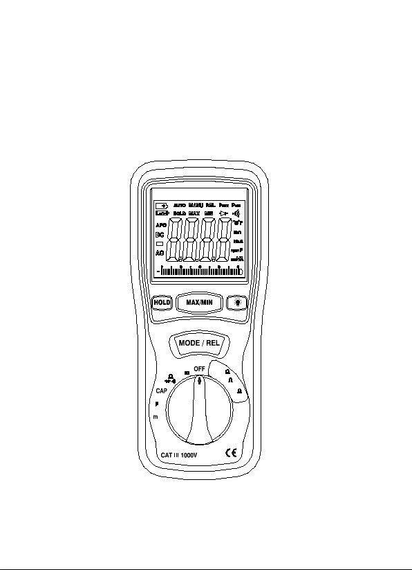
Low Resist anc e Tester
400m
4
40
V
A
A
4
(2)
1
(3)
(1) (2)
(1) (1)
(2)

1

2
I. SAFETY INFORMATION
1. NEVER apply voltage or current to the meter that exceeds the
specified maximum:
2. USE EXTREME CAUTION when working with high voltages.
3. DO NOT measure voltage if the voltage on the "COM" input
jack exceeds 1000V above earth ground.
4. NEVER connect the meter leads across a voltage source while
the function switch is in the current, resistance, or diode mode.
Doing so can damage the meter.
5. ALWAYS discharge filter capacitors in power supplies and
disconnect the power when making resistance or diode tests.
6. ALWAYS turn off the power and disconnect the test leads
before opening the covers to replace the fuse or batteries.
7. NEVER operate the meter unless the back cover and the
battery and fuse covers are in place and fastened securely.
8. If the equipment is used in a manner not specified by the
manufacturer, the protection provided by the equipment may
be impaired.
3
Safety symbols:
Caution refer to this manual before using the meter.
Dangerous voltages.
Meter is protected throughout by double insulation or
reinforced insulation.
When servicing, use only specified replacement parts.
CE Comply with EN-61010-1
II
.
OPERATING PRINCIPLE
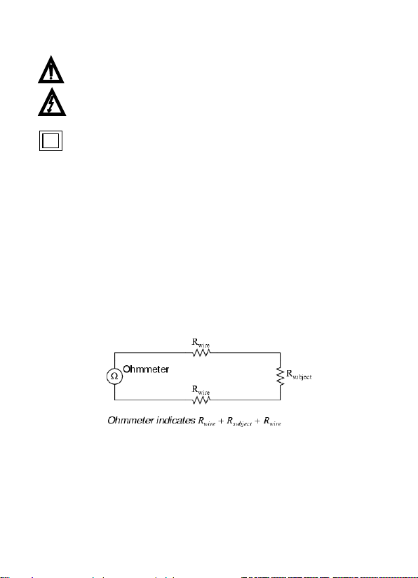
Suppose we wished to measure the resistance of some component
located a significant distance away from our ohmmeter. Such a
scenario would be problematic, because an ohmmeter measures all
resistance in the circuit loop, which includes the resistance of the
wires (Rwire) connecting the ohmmeter to the component being
measured (Rsubject):
Usually, wire resistance is very small (only a few ohms per hundreds
of feet, depending primarily on the gauge (size) of the wire), but if
the connecting wires are very long, and/or the component to be
measured has a very low resistance anyway, the measurement error
introduced by wire resistance will be substantial.
4
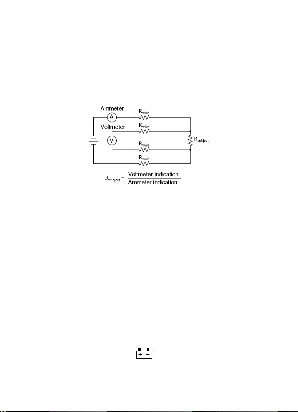
An ingenious method of measuring the subject resistance in a
situation like this involves the use of both an ammeter and a
voltmeter. We know from Ohm's Law that resistance is equal to
voltage divided by current (R = E/I). Thus, we should be able to
determine the resistance of the subject component if we measure
the current going through it and the voltage dropped across it:
Current is the same at all points in the circuit, because it is a series
loop. Because we're only measuring voltage dropped across the
subject resistance (and not the wires' resistances), though, the
calculated resistance is indicative of the subject
component's resistance (Rsubject ) alone.
III. FEATURES
Low resistance range: 0~40Ω
Display: Large LCD with bar graph display
Maximum output current : 200mA (400mΩ)
Sampling Rate: 2 times per second.
relative measurement
Over Range Indicator: OL of highest digit is displayed.
Low Battery Indication: The is displayed when the
battery Voltage drop below the operating voltage.

5
Auto Power Off
To conserve battery life, the meter will automatically turn off after
approx. 30 minutes of non-use. When this happens, the state of the
meter is saved. In order to disable auto power off function, power on
the meter when any of the push function , except for HOLD, is
pressed down.The “APO” sign on the LCD panel indicates whether
the auto power-off function is enabled or not.
Operating Temperature: 0ºC to 40ºC (32ºF to 104ºF)
and Humidity below 80% RH
Storage Temperature: -10ºC to 60ºC (14ºF to 140ºF)
and Humidity below 70% RH
Power source: 6x1.5V Size “AA” battery or Equivalent (DC9V)
Dimensions: 200(L) x 92(W) x 50(H) mm
Weight: Approx 700g include battery
Accessories: 4 sets Te st kits, 4pcs iron rods, 6pcs battery, Carrying
case, manual.
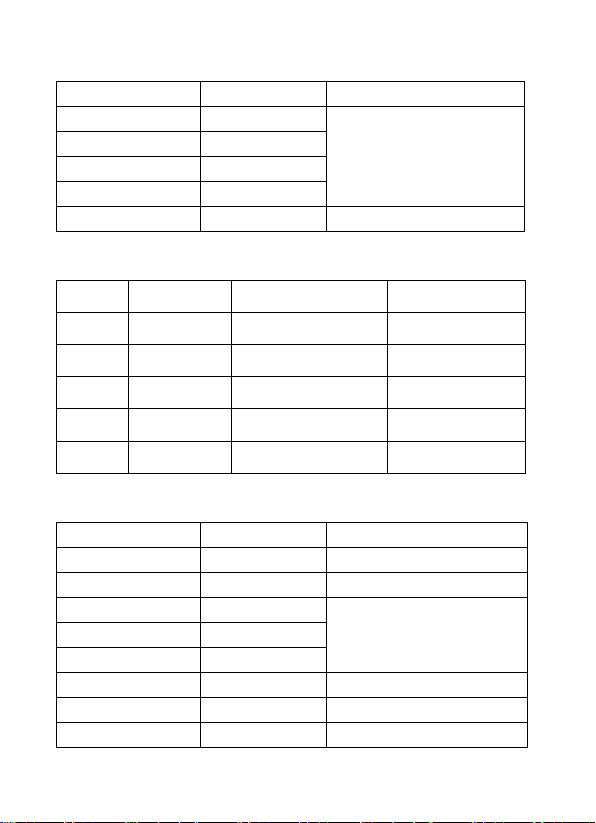
IV. Electrical Specifications
Accuracies are specified in the way:
± (…% of reading +…digits) at 23ºC ± 5ºC,below 80% RH.
Low resistance
Range
Resolution
Accuracy
Current
400mΩ
0.1mΩ
± (1%+10d)
200mA
4Ω
1mΩ
± (1%+5d)
20mA
40Ω
0.01Ω
± (1%+5d)
2mA

6
OHMS
Range
Resolution
Accuracy
400Ω
0.1Ω
± (1.0% + 4d)
4KΩ
1Ω
± (1.5% + 2d)
40KΩ
10Ω
400KΩ
100Ω
4MΩ
1K
± (2.5% + 3d)
40MΩ
10kΩ
± (3.5% + 5d)
DC Current
Rang
Resolution
Accuracy
400µA
0.1µA
± (1.5%+5d)
4000µA
1µA
40mA
0.01mA
400mA 0.1mA
AC Current
Rang
Resolution
Accuracy/50~60Hz
Accuracy/400Hz
400µA
0.1µA
± (1.5%+5d)
± (1.5%+5d)
4000µA
1µA
± (1.5%+5d)
± (1.5%+5d)
40mA
0.01mA
± (1.5%+5d)
± (1.5%+5d)
400mA
0.1mA
± (1.5%+5d)
± (1.5%+5d)
7
DC Voltage
Rang
Resolution
Accuracy
400mV
0.1 mV
± (1%+5d)
4V
1 mV
40V
0.01V
400V
0.1V
1000V
1V
± (1.2%+5d)
AC Voltage
Rang Resolution Accuracy/50~60Hz Accuracy/400Hz
400mV 0.1 mV ± (1.2%+10d) ± (2.5%+10d)
4V 1 mV ± (1.0%+10d) ± (1.2%+10d)
40V 0.01V ± (1.0%+10d) ± (1.2%+10d)
400V 0.1V ± (1.0%+10d) ± (1.2%+10d)
750V 1V ± (1.0%+10d) ± (1.2%+10d)
Capacitance
Rang
Resolution
Accuracy
4nF
1pF
unspecified
40nF
10PF
± (5.0% + 20d)
400nF
0.1nF
± (3%+10d)
4uF
1nF
40uF
10nF
400uF
0.1uF
± (4%+10d)
4mF
1uF
± (10%+10d)
40mF
10uF
unspecified
8
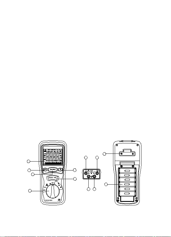
V. PARTS & CONTROLS
①Digital Display
②Data Hold Button
③MAX/MIN Button
④Backlight Button
⑤Mode/REL Button
⑥Rotary Function switch
⑦V Ω Cap mA E2 Jack
⑧COM E1 jack
⑨P2 Jack
⑩P1 jack
⑪PothooK
⑫Battery Cover
Low Resista nce Tester
E
P
E
P
12
2 1
V
400m
4
40
V
A
A
AA
+
+
AA
+
AA
AA
+
+
AA
+
AA
4
(2)
1
(3)
(1)(2)
(1) (1)
(2)
1
2
3
5
7
4
8
12
69
10
11

9
Button Function Operation
HOLD button
The HOLD function allows the meter to "freeze" a measurement for
later reference.
1. Press the HOLD button to “freeze” the reading on the indicator.
The “HOLD” message will be appear in the display.
2. Press the HOLD button again to return to normal operation.
MAX/MIN button
The MAX/MIN function allows the meter to capture the highest or
lowest measurement for later reference.
1 Press the MAX/MIN button to begin measurement. The indicator
“MAX” or “MIN” will appear in the display.
2. If the “MAX MIN” messages are flashing, the instrument is in
MAX/MIN mode but not recording, press the MAX/MIN button to
select a mode.
3. To return to normal AUTO measurement mode, hold down the
MAX/MIN button for 2 seconds.
Backlight
Press the key for to turn on the display backlight function.
The backlight will automatically turn off after 15 seconds.
MODE/REL button
To select AC or DC measurement when in Voltages, mA , uA ,Ω,
, •))) . RELATIVE ZERO BUTTON:
For convenient readings comparison & offset when in low resistance
test .

10
DC/AC VOLTAGE MEASUREMENT
1. Sert the black test lead into the negative COM jack and the red
test lead into the V Ω Cap mA E2 Jack
2. Set the function switch to the V position.
3. Use the MODE button to select AC or DC Voltage
4. Connect the test leads in parallel to the circuit under test.
5. Read the voltage measurement on the LCD display
DC/AC CURRENT MEASUREMENT
1. Insert the black test lead banana plug into the negative (COM)
jack.
2. For current measurements up to 4000uA, set the function switch
to the uA position.
3. For current measurements up to 400mA, set the function switch
to the mA range.
4. Press the ‘MODE/REL’ button until “DC” or “AC” appears in the
display.
5. Remove power from the circuit under test, then open up the
circuit at the point where you wish to measure current.
6. Touch the black test probe tip to the negative side of the circuit.
Touch the red test probe tip to the positive side of the circuit.
7. Apply power to the circuit.
8. Read the current in the display. The display will indicate the
proper decimal point, value and symbol.

11
RESISTANCE [ Ω ] MEASUREMENT
WARNING: To avoid electric shock, disconnect power to the
unit under test and discharge all capacitors before taking any
resistance measurements. Remove the batteries and unplug the
line cords.
1. Set the function switch to the Ωposition.
2. Insert the black test lead plug into the negative (COM) socket
and the red test lead plug into the positive Ω jack.
3. Press the MODE button until “Ω” appears in the display.
4. Touch the test probe tips across the circuit or part under test. It is
best to disconnect one side of the part under test so the rest of
the circuit will not interfere with the resistance reading.
5. Read the resistance in the display. The display will indicate the
proper decimal point, value and symbol.
CONTINUITY CHECK
WARNING: To avoid electric shock, never measure continuity
on circuits or wires that have voltage on them.
1. Set the range switch to the •))) position.
2. Insert the black lead plug into the COM socket and the red
test lead plug into the positive •))) socket.
3. Press the MODE button until “•)))” appears in the displa
4. Touch the test probe tips to the circuit or wire you wish to
check.
5. If the resistance is less than 35Ω, the audible signal will sound.
The display will also show the actual resistance in ohms.
12
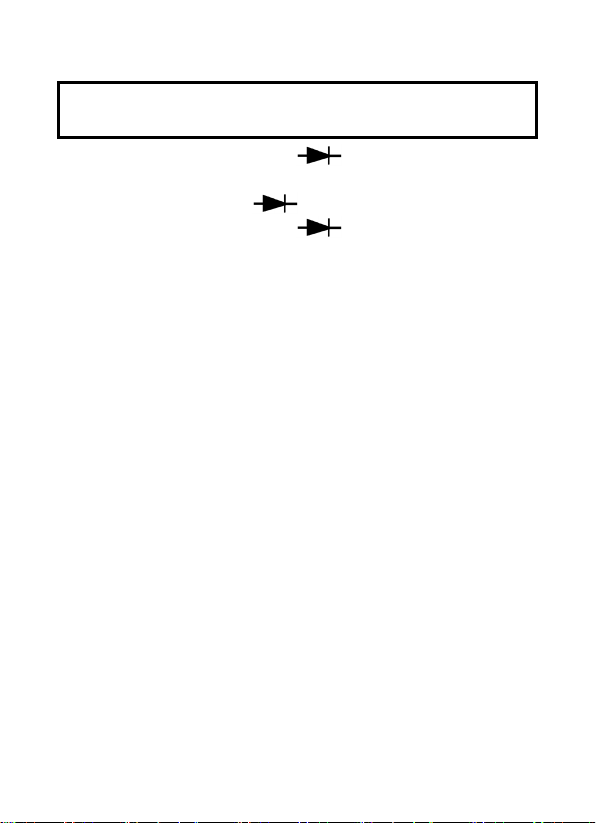
DIODE TEST
WARNING: To avoid electric shock, do not test any diode that
has voltage on it.
1. Set the function switch to the position.
2. Insert the black test lead plug into the COM socket and the red
test lead plug into the socket.
3. Press the MODE button until “ ” appears in the display.
4. Touch the test probe tips to the diode or semiconductor junction
you wish to test. Note the meter reading.
5. Reverse the probe polarity by switching probe position. Note
this reading.
6. The diode or junction can be evaluated as follows:
A. If one reading shows a value and the other reading shows
OL, the diode is good.
B. If both readings show OL, the device is open.
C. If both readings are very small or zero, the device is shorted.
NOTE: The value indicated in the display during the diode check is
the forward voltage.
CAPACITANCE MEASUREMENT
WARNING: To avoid electric shock, discharge the capacitor under
test before measuring.
1 Set the function switch to the CAP capacitance position.
2 Insert the black test lead banana plug into the negative COM
jack and the red test lead banana plug into the CAP positive
jack.
13
3 Touch the test probe tips across the part under test.
4 Read the capacitance value in the display.
5 The display will indicate the proper decimal point and value.
Note: For very large values of capacitance measurement time can
be several minutes before the final reading stabilizes. The LCD
displays DSC when discharging. Discharging through the chip is
quite slow. We recommend the user to discharge the capacitor with
some other apparatus.
Low resistance measurement
WARNING: To avoid electric shock, disconnect power to the
unit under test and discharge all capacitors before taking any
resistance measurements.
1. Insert the red test leads banana plug into E2,P2 red com
jack,and black test leads banana plug into E1,P1 black com
jack.
2. At the range of 40 Ω, connect the clips to the low resistance’s
terminals, If the reading is too low then switch the range to 4 Ω
or 400m Ω.
3. Remove the clips from the low resistance terminals, and connect
then each other ,then press “ MODE/REL” button.
4 . Connect the clips to the low resistance’s terminal again.
5 . Read the resistance in the display. The display will indicate the
proper decimal point, value and symbol.
14
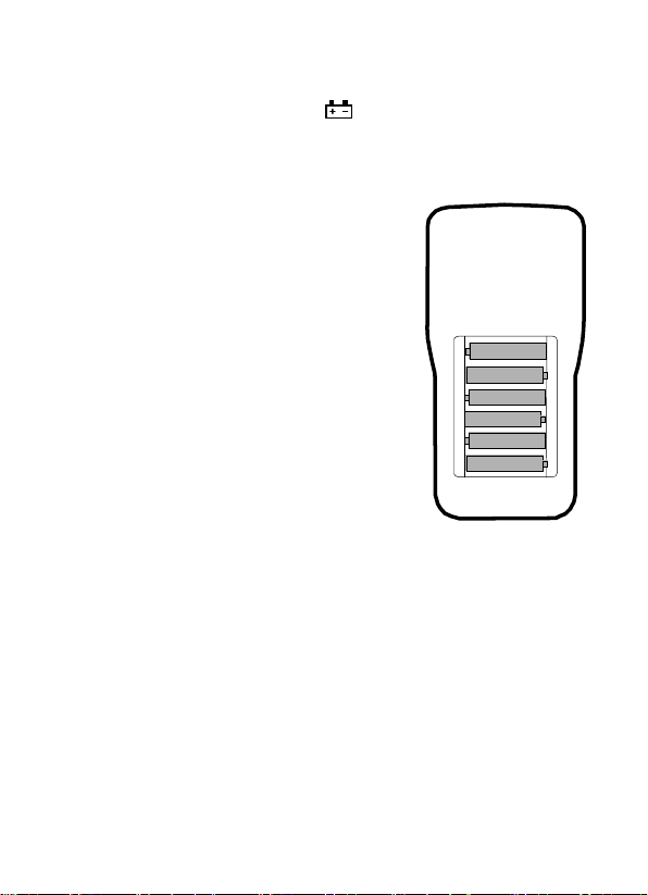
VI. Battery Replacement
1. When the low battery symbol appears on the LCD,
the six 1.5V ‘AA’ batteries must be replaced.
2. Turn the meter off and remove the test leads.
3. Unsnap the tilt stand from the rear of the meter.
4. Remove the four Phillips head screws
holding the battery cover.
5. Remove the battery compartment cover
6. Replace the batteries observing
Polarity.
7. Affix the rear cover and secure the
screws.
8. Reattach the tilt stand.

15
V06/08
Table of contents
Other CEM Test Equipment manuals


