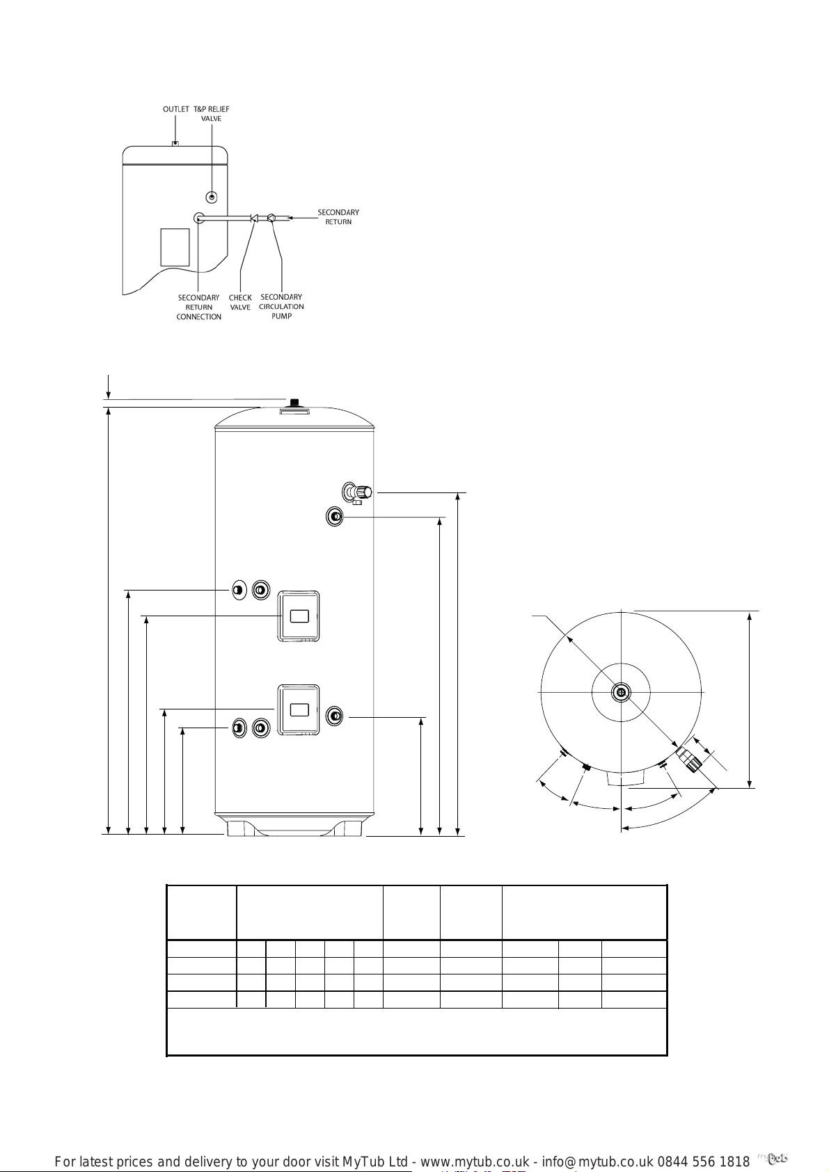
6
Worked example of discharge pipe sizing
Fig. 5 is for a G1/2 temperature relief valve with a dis-
charge pipe (D2) having 4 No. elbows and length of 7m
from the tundish to the point of discharge.
From Table 3:
Maximum resistance allowed for a straight length of
22mm copper discharge pipe (D2) from a G1/2 tem-
perature relief valve is 9.0m.
DISCHARGE PIPEWORK
It is a requirement of Building Regulation G3 that any
discharge from an unvented system is conveyed to
where it is visible, but will not cause danger to persons
in or about the building.The tundish and discharge
pipes should be fitted in accordance with the require-
ments and guidance notes of Building Regulation G3.
The G3 Requirements and Guidance section 3.9 are
reproduced in the following sections of this manual.
Information Sheet No. 33 available from the British
Board of Agrément gives further advice on discharge
pipe installation. For discharge pipe arrangements not
covered by G3 Guidance or BBA Info Sheet No.33
advice should be sought from your local Building
Control Officer.
Any discharge pipe connected to the pressure relief
devices (Expansion Valve and Temperature/Pres-
sure Relief Valve) must be installed in a continuously
downward direction and in a frost free environment.
The water may drip from the discharge pipe of the
pressure relief device.This pipe must be left open to
the atmosphere.The pressure relief device is to be op-
erated regularly to remove lime deposits and to verify
that it is not blocked.
G3 REQUIREMENT
“...there shall be precautions...to ensure that
the hot water discharged from safety devices is
safely conveyed to where it is visible but will not
cause danger to persons in or about the build-
ing.”
G3 GUIDANCE SECTION 3.9
The discharge pipe (D1) [see fig.5 in this instruc-
tion book] from the vessel up to and including
the tundish is generally supplied by the manu-
facturer of the hot water storage system.Where
otherwise, the installation should include the
discharge pipe(s) (D1) from the safety device(s).
In either case the tundish should be vertical,
located in the same space as the unvented hot
water storage system and be fitted as close as
possible and within 500mm of the safety device
e.g. the temperature relief valve.
The discharge pipe (D2) from the tundish should
terminate in a safe place where there is no risk
to persons in the vicinity of the discharge,prefer-
ably be of metal and:
a. be at least one pipe size larger than the
nominal outlet size of the safety device unless its
total equivalent hydraulic resistance exceeds that
of a straight pipe 9m long i.e. discharge pipes
between 9m and 18m equivalent resistance
length should be at least two sizes larger than
the nominal outlet size of the safety device,
between 18 and 27m at least 3 sizes larger ,
and so on. Bends must be taken into account
in calculating the flow resistance.Refer to Table
3,Table 1 and the worked example [see Table 3
and Fig.5 in this instruction book].
An alternative approach for sizing discharge
pipes would be to follow BS 6700:1987 Specifica-
tion for design installation, testing and main-
tenance of services supplying water for domestic
use within buildings and their curtilages, Appen-
dix E,section E2 and table 21.
b. have a vertical section of pipe at least 300mm
long, below the tundish before any elbows or
bends in the pipework.
c. be installed with a continuous fall and in a
frost free environment.
d. have discharges visible at both the tundish
and the final point of discharge but where this
is not possible or is practically difficult there
should be clear visibility at one or other of these
locations.Examples of acceptable discharge
arrangements are:
i. ideally below a fixed grating and above the
water seal in a trapped gully.
ii. downward discharges at low level; i.e. up
to 100mm above external surfaces such as
car parks, hard standings, grassed areas etc.
are acceptable providing that where children
may play or otherwise come into contactwith
discharges a wire cage or similar guard is posi-
tioned to prevent contact,whilst maintaining
visibility.
iii. discharges at high level; e.g. into a metal
hopper and metal down pipe with the end
of the discharge pipe clearly visible (tundish
visible or not) or onto a roof capable of
withstanding high temperature discharges
of water and 3m from any plastics guttering
system that would collect such discharges
(tundish visible).
iv. where a single pipe serves a number of
discharges, such as in blocks of flats, the
number served should be limited to not
more than 6 systems so that any installation
discharging can be traced reasonably easily.
The single common discharge pipe should be
at least one pipe size larger than the largest
individual discharge pipe (D2) to be con-
nected. If unvented hot water storage systems
are installed where discharges from safety
devices may not be apparent i.e.in dwellings
occupied by blind, infirm or disabled people,
consideration should be given to the instal-
lation of an electronically operated device to
warn when discharge takes place.
Note:The discharge will consist ofscalding
water and steam.Asphalt,roofing felt and
non-metallic rainwater goods may be
damaged by such discharges.
For latest prices and delivery to your door visit MyTub Ltd - www.mytub.co.uk - [email protected] 0844 556 1818 


 Operation and maintenance instructions")