Central Machinery 65558 User guide

TURF/SOD CUTTER
WITH 4 HP ENGINE
65558
SET UP, OPERATING, AND SERVICING
INSTRUCTIONS
Using an engine indoors CAN KILL YOU IN
MINUTES.
Engine exhaust contains carbon monoxide.
This is a poison you cannot see or smell.
NEVER use inside
a home or garage,
EVEN IF doors and
windows are open.
Only use OUTSIDE
and far away from
windows, doors, and
vents.
Distributed exclusively by Harbor Freight Tools®.
3491 Mission Oaks Blvd., Camarillo, CA 93011
Visit our website at: http://www.harborfreight.com
Read this material before using this product.
Failure to do so can result in serious injury.
SAVE THIS MANUAL.
Copyright©2008 by Harbor Freight Tools®. All rights reserved. No portion of this manual or any artwork
contained herein may be reproduced in any shape or form without the express written consent of
Harbor Freight Tools. Diagrams within this manual may not be drawn proportionally. Due to continuing
improvements, actual product may differ slightly from the product described herein. Tools required for
assembly and service may not be included.
For technical questions or replacement parts, please call 1-800-444-3353.

SKU 65558 For technical questions, please call 1-800-444-3353. Page 2
TABLE OF CONTENTS
READ THIS MANUAL......................................................................................................3
IMPORTANT SAFETY INFORMATION............................................................................3
SET UP PRECAUTIONS..................................................................................................3
OPERATING PRECAUTIONS..........................................................................................4
SERVICE PRECAUTIONS...............................................................................................5
UNPACKING....................................................................................................................6
ASSEMBLY INSTRUCTIONS..........................................................................................6
OPERATING INSTRUCTIONS.........................................................................................7
TECHNICAL SPECIFICATIONS....................................................................................12
SERVICING....................................................................................................................12
MAINTENANCE, LUBRICATION, CLEANING SCHEDULE.........................................16
TROUBLESHOOTING - TURF/SOD CUTTER UNIT.....................................................17
TROUBLESHOOTING - ENGINE..................................................................................18
PARTS LIST - TURF/SOD CUTTER UNIT.....................................................................20
ASSEMBLY DIAGRAM - TURF/SOD CUTTER UNIT....................................................21
PARTS LIST - ENGINE..................................................................................................22
ASSEMBLY DIAGRAM - ENGINE.................................................................................23
WARRANTY INFORMATION.........................................................................................24
PLEASE READ THE FOLLOWING CAREFULLY.........................................................25

SKU 65558 For technical questions, please call 1-800-444-3353. Page 3
SAVE THIS MANUAL
Keep this manual for the safety warn-
ings and precautions, assembly, operating,
inspection, maintenance and cleaning pro-
cedures. Write the product’s serial number
in the back of the manual (or month and
year of purchase if product has no num-
ber). Keep this manual and the receipt in
a safe and dry place for future reference.
IMPORTANT SAFETY
INFORMATION
In this manual, on the labeling,
and all other information
provided with this product:
This is the safety alert
symbol. It is used to alert
you to potential personal
injury hazards. Obey all
safety messages that
follow this symbol to avoid
possible injury or death.
DANGER indicates
a hazardous
situation which, if not
avoided, will result in death or
serious injury.
WARNING
indicates a
hazardous situation which, if
not avoided, could result in
death or serious injury.
CAUTION, used
with the safety
alert symbol, indicates a
hazardous situation which, if
not avoided, could result in
minor or moderate injury.
NOTICE is used to
address practices
not related to personal injury.
CAUTION, without
the safety alert
symbol, is used to address
practices not related to
personal injury.
WARNING! Read all instructions.
Failure to follow all instructions
listed below may result in re,
serious injury and/or DEATH.
The warnings and precautions
discussed in this manual cannot
cover all possible conditions and
situations that may occur. It must
be understood by the operator that
common sense and caution are
factors which cannot be built into
this product, but must be supplied
by the operator.
SAVE THESE INSTRUCTIONS
SET UP PRECAUTIONS
Gasoline fuel and fumes are amma-1.
ble, and potentially explosive. Use
proper fuel storage and handling pro-
cedures. Do not store fuel or other
ammable materials nearby.
Have multiple ABC class re extin-2.
guishers nearby.
Operation of this equipment may cre-3.
ate sparks that can start res around
dry vegetation.
A spark arrestor may be required.
The operator should contact local re
agencies for laws or regulations relat-
ing to re prevention requirements.
Set up and use only on a at, level, 4.
well-ventilated surface.

SKU 65558 For technical questions, please call 1-800-444-3353. Page 4
Wear ANSI-approved safety goggles,5.
heavy-duty work gloves, and dust
mask/respirator during set up.
Use only oil and fuel recommended6.
in the “Specications” section of this
manual.
OPERATING PRECAUTIONS
1. CARBON MONOXIDE
HAZARD
Using an engine indoors
CAN KILL YOU IN
MINUTES.
Engine exhaust contains carbon
monoxide. This is a poison you
cannot see or smell.
NEVER use inside a home or garage,
EVEN IF doors and windows are
open.
Only use OUTSIDE and far away
from windows, doors, and vents.
Risk of serious cuts. Keep hands,2.
ngers, and feet out from under the
equipment when operating.
Burn hazard. Do not touch or lean/3.
reach over a hot engine.
Entanglement hazard. Keep hands4.
and ngers away from V-Belts when
operating.
Tipping hazard. Do not operate on5.
grades over 35%.
Underground hazards. Be aware of6.
buried cables, pipes, tree roots, etc.
prior to operating the equipment.
Keep children away from the equip-7.
ment, especially while it is operating.
Do not leave the equipment unat-8.
tended when it is running. Turn off
the equipment before leaving the
work area.
Wear ANSI-approved safety goggles9.
and hearing protection during use.
People with pacemakers should10.
consult their physician(s) before
use. Electromagnetic elds in close
proximity to a heart pacemaker could
cause pacemaker interference or
pacemaker failure. Caution is neces-
sary when near the engine’s magneto
or recoil starter.
Use only accessories that are recom-11.
mended by Harbor Freight Tools for
your model. Accessories that may be
suitable for one piece of equipment
may become hazardous when used
on another piece of equipment.
Do not operate in explosive atmo-12.
spheres, such as in the presence of
ammable liquids, gases, or dust.
Gasoline-powered engines may ignite
the dust or fumes.
Stay alert, watch what you are doing13.
and use common sense when operat-
ing this piece of equipment. Do not
use this piece of equipment while
tired or under the inuence of drugs,
alcohol or medication.

SKU 65558 For technical questions, please call 1-800-444-3353. Page 5
Do not overreach. Keep proper foot-14.
ing and balance at all times. This en-
ables better control of the equipment
in unexpected situations.
Use this equipment with both hands15.
only. Using equipment with only
one hand can easily result in loss of
control.
Dress properly. Do not wear loose16.
clothing or jewelry. Keep hair, cloth-
ing and gloves away from moving
parts. Loose clothing jewelry or long
hair can be caught in moving parts.
Parts, especially exhaust system17.
components, get very hot during use.
Stay clear of hot parts.
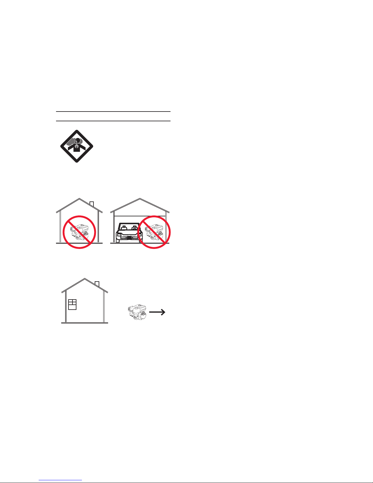
Do not cover the engine or equipment18.
during operation.
Keep the equipment, engine, and sur-19.
rounding area clean at all times.
Use the equipment, accessories, etc.,20.
in accordance with these instructions
and in the manner intended for the
particular type of equipment, taking
into account the working conditions
and the work to be performed. Use
of the equipment for operations differ-
ent from those intended could result
in a hazardous situation.
Do not operate the equipment with21.
known leaks in the engine’s fuel sys-
tem.
This product contains or, when used,22.
produces a chemical known to the
State of California to cause cancer
and birth defects or other reproduc-
tive harm. (California Health & Safety
Code § 25249.5, et seq.)
When spills of fuel or oil occur, they23.
must be cleaned up immediately.
Dispose of uids and cleaning materi-
als per local, state, or federal codes
and regulations. Store oil rags in a
bottom-ventilated, covered, metal
container.
Keep hands and feet away from24.
moving parts. Do not reach over or
across equipment while operating.
Before use, check for misalignment25.
or binding of moving parts, breakage
of parts, and any other condition that
may affect the equipment’s operation.
If damaged, have the equipment
serviced before using. Many ac-
cidents are caused by poorly main-
tained equipment.
Use the correct equipment for the26.
application. Do not modify the equip-
ment and do not use the equipment
for a purpose for which it is not in-
tended.
SERVICE PRECAUTIONS
Before service, maintenance, or1.
cleaning:
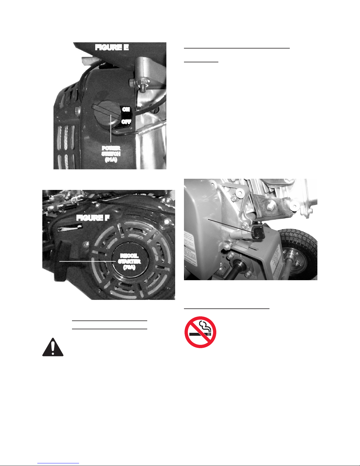
Turn the engine power switch toa.
its “OFF” position.
Allow the engine to completelyb.
cool.
Then, remove the spark plug.c.
Keep all safety guards in place and in2.
proper working order. Safety guards
include mufer, air cleaner, mechani-
cal guards, and heat shields, among
other guards.
Do not alter or adjust any part of the3.
equipment or its engine that is sealed
by the manufacturer or distributor.

SKU 65558 For technical questions, please call 1-800-444-3353. Page 6
Only a qualied service technician
may adjust parts that may increase or
decrease governed engine speed.
Wear ANSI-approved safety goggles,4.
heavy-duty work gloves, and dust
mask/respirator during service.
Maintain labels and nameplates on5.
the equipment. These carry impor-
tant information. If unreadable or
missing, contact Harbor Freight Tools
for a replacement.
Have the equipment serviced by a6.
qualied repair person using only
identical replacement parts. This will
ensure that the safety of the equip-
ment is maintained. Do not attempt
any service or maintenance proce-
dures not explained in this manual
or any procedures that you are un-
certain about your ability to perform
safely or correctly.
Store equipment out of the reach of7.
children.
Follow scheduled engine and equip-8.
ment maintenance.
Refueling Precautions:9.
Do not smoke, or allow sparks,a.
ames, or other sources of ignition
around the equipment, especially
when refuelling.
Do not rell the fuel tank while the b.
engine is running or hot.
Do not ll fuel tank to the top. Leave c.
a little room for the fuel to expand as
needed.
Refuel in a well-ventilated area only.d.
SAVE THESE INSTRUCTIONS.
UNPACKING
When unpacking, check to make sure
that the item is intact and undamaged. If
any parts are missing or broken, please
call Harbor Freight Tools at the number
shown on the cover of this manual as soon
as possible.
ASSEMBLY INSTRUCTIONS
Read the ENTIRE IMPORTANT
SAFETY INFORMATION
section at the beginning of this
manual including all text under
subheadings therein before set
up or use of this product.
TO PREVENT
SERIOUS INJURY
FROM ACCIDENTAL
STARTING:
Turn the Power Switch of the
equipment to its “OFF”
position, wait for the engine to
cool, and remove the spark
plug before assembling or
making any adjustments to
the equipment.
TO PREVENT
SERIOUS INJURY:
Operate only with proper
spark arrestor installed.
Operation of this equipment
may create sparks that
can start res around dry
vegetation.
A spark arrestor may be
required.
The operator should contact
local re agencies for laws
or regulations relating to re
prevention requirements.

SKU 65558 For technical questions, please call 1-800-444-3353. Page 7
Note: For additional information regarding
the parts listed in the following pages,
refer to the Assembly Diagram near
the end of this manual.
Attach the Handle (5) to the Frame1.
(42) using three Bolts (10), three
Spring Washers (8), and three Flat
Washers (9). (See Figure A.)
Attach the Clutch Handle Rod (6)2.
to the Clutch Handle (17) using two
Bolts (10), four Flat Washers (9), two
Spring Washers (8), and two Lock
Nuts (7). (See Figure B.)
FIGURE B
BOLTS (10)
FLAT WASHERS (9)
SPRING WASHERS (8)
LOCK NUTS (7)
CLUTCH
HANDLE
ROD
(6)
CLUTCH
HANDLE
(17)
OPERATING INSTRUCTIONS
Read the ENTIRE IMPORTANT
SAFETY INFORMATION
section at the beginning of this
manual including all text under
subheadings therein before set
up or use of this product.
Engine Controls
FIGURE C
CHOKE
LEVER
FUEL
VALVE
FIGURE D
THROTTLE
LEVER
(2)
FIGURE A
BOLT
(11)
SPRING
WASHER
(9)
FLAT
WASHER
(8)
HANDLE
(5)
FRAME
(42)

SKU 65558 For technical questions, please call 1-800-444-3353. Page 8
Starting the Engine
Inspect engine and equipment
looking for damaged, loose, and
missing parts before set up and
starting. If any problems are
found, do not use equipment
until properly repaired.
FIGURE E
POWER
SWITCH
(81A)
ON
OFF
FIGURE F
RECOIL
STARTER
(76A)
Checking and Filling Engine Oil
CAUTION! Your Warranty is VOID if the
engine’s crankcase is not properly
lled with oil before each use. Before
each use, check the oil level. Do not
run the engine with low or no engine
oil. Running the engine with no or
low engine oil WILL permanently
damage the engine.
Wipe outside of Dipstick, unscrew1.
and remove. Wipe Dipstick. Insert
in the hole without threading it. Re-
move and read oil label.
(See Figure G.)
FIGURE G
DIPSTICK
(20A)
Checking and Filling Fuel
WARNING! TO PREVENT
SERIOUS INJURY FROM
FIRE:
Fill the Fuel Tank in a well-
ventilated area away from ignition
sources. Do not smoke.
To ll the Fuel Tank (89A), rst wipe 1.
off the Fuel Tank Cap (91A) and the
surrounding area.
(See Figure H.)

SKU 65558 For technical questions, please call 1-800-444-3353. Page 9
Unscrew, and remove the Fuel Tank2.
Cap (91A). (See Figure H.)
Remove the Fuel Tank Strainer (90A)3.
and remove any dirt and debris.
Then replace the Fuel Tank Filter.
(See Figure H.)
Fill the Fuel Tank (8A9) to about 14.
inch under the ll neck of the Tank
with unleaded gasoline.
(See Figure H.)
Then replace the Fuel Tank Cap5.
(91A).
(See Figure H.)
FIGURE H
FUEL
TANK
CAP
(91A)
FUEL
TANK
FILTER
(90A)
Start Procedure:
Before starting the engine:
Follow the Set Up Instruc-a.
tions to prepare the equip-
ment.
Inspect the equipment andb.
Engine.
Fill the Engine with the prop-c.
er amount and type of fuel
and oil.
Read the Equipment Opera-d.
tion section that follows.
Turn the Engine Fuel Valve to its1.
“OPEN” position. (See Figure C.)
Turn the Engine Choke Lever to its2.
“CHOKE” position. Set the Choke
Lever in the “RUN” position when
starting a warm Engine.
(See Figure C.)
Push the Throttle Lever (2) all the3.
way forward. (See Figure D.)
Then turn the Engine Power Switch4.
(81A) to its “ON” position.
(See Figure E.)
Grasp the Recoil Starter (76A), and5.
pull slowly until resistance is felt.
While holding the Recoil Starter, al-
low the Starter Rope to rewind slow-
ly. Then, pull the Recoil Starter with
a rapid, full arm stroke. Once again
while holding the Recoil Starter, allow
the Rope to rewind slowly. Repeat
as necessary, until the Engine starts.
(See Figure F.)
After the Engine starts and warms6.
up, slowly move the Choke Lever to
its “RUN” position. (See Figure C.)
To adjust the Engine’s speed, move7.
the Throttle forward for increased
speed. Move the Throttle backward
for decreased speed.
(See Figure D.)
IMPORTANT: Allow the Engine to8.
run at no load until warm (1-5 min-
utes) with no load after each start-up
to allow the Engine to stabilize.

SKU 65558 For technical questions, please call 1-800-444-3353. Page 10
Break-in Period:
Breaking-in the Engine will help to1.
ensure proper equipment and Engine
operation, and will extend the En-
gine’s lifespan. The warranty is void
if the Engine is not broken in properly.
The rst 20 hours of operation is the
break-in period.
During the rst 3 hours of use:2.
Do not apply a heavy load to the•
equipment.
Do not operate the Engine at its•
maximum speed.
After the rst 20 hours of use:3.
Change the engine oil.•
Under normal operating conditions•
subsequent maintenance follows
the schedule explained in the
MAINTENANCE AND SERVICING
section.
Equipment Operation
To Transport the Turf/Sod Cutter:
Loosen the two Lock Bolts (19) at the1.
rear of the Frame (42).
(See Figure I.)
Crank the Handle (23) to lower the2.
two rear Wheels (54) all the way
down so that they contact the ground
surface. Then retighten the two Lock
Bolts (19). (See Figure I.)
Disengage the unit’s Clutch by pulling3.
the Clutch Handle Rod (6) downward.
Then push the Turf/Sod Cutter to the
work location. (See Figure I.)
FIGURE I
LOCK BOLT
(19)
LOCK BOLT
(19)
HANDLE
(23)
CLUTCH HANDLE ROD
(6)
KNIFE
(43)
To Operate the Turf/Sod Cutter:
Make sure the Clutch Handle Rod (6)1.
is in its disengaged (lowered) posi-
tion. (See Figure I.)
Loosen the two Lock Bolts (19) at the2.
rear of the Frame (42).
(See Figure I.)
To set the cutting depth (up to 2”) of3.
the Knife (43), turn the Handle (23)
and raise the two rear Wheels (54)
until the desired cutting depth is ob-
tained . Then retighten the two Lock
Bolts (19). (See Figure I.)
Start the Engine (31), and allow it to4.
warm up as previously discussed in
this manual.
Once the Engine (31) is started, raise5.
the Clutch Handle Rod (6) to engage
the unit’s Clutch. The Turf/Sod Cut-
ter will now self-propel forward.
(See Figure J, next page.)
As the Turf/Sod Cutter moves for-6.
ward, you may wish to regulate the
speed at which it travels by adjusting
the Throttle Lever (2).
(See Figure J.)

SKU 65558 For technical questions, please call 1-800-444-3353. Page 11
FIGURE J
THROTTLE LEVER (2)
CLUTCH HANDLE ROD
(6)
KNIFE
(43)
HANDLE
(23)
LOCK BOLT
(19)
LOCK BOLT
(19)
7. Do not force (push) the Turf/Sod Cut-
ter. Allow the unit to move forward on
its own and do the work at the speed
at which it was previously set.
To obtain an even depth of cut over8.
the entire work area, follow the cut-
ting pattern as shown below. (i.e.,
cut rows #1, #2, #3, #4, and #5 rst.
Then cut rows #6, #7, #8, and #9)
(See Figure K.)
FIGURE K
When nished cutting, adjust the 9.
Throttle Lever (2) to its lowest speed
setting. (See Figure J.)
Disengage the unit’s Clutch by pulling10.
the Clutch Handle Rod (6) downward.
(See Figure L.)
Loosen the two Lock Bolts (19) at the11.
rear of the Frame (42).
(See Figure L.)
Turn the Handle (23) to lower the two12.
rear Wheels (54) and raise the Knife
(43) up from the ground surface.
Then retighten the two Lock Bolts
(19). (See Figure L.)
Turn off the Engine (31), and allow13.
the unit to completely cool before
transporting and/or storing.
FIGURE L
LOCK BOLT
(19)
LOCK BOLT
(19)
HANDLE
(23)
CLUTCH HANDLE ROD
(6)
KNIFE
(43)

SKU 65558 For technical questions, please call 1-800-444-3353. Page 12
TECHNICAL SPECIFICATIONS
Engine Type
4 HP, 4 Stroke, OHV,
Single Cylinder,
Air Cooled.
Displacement 119cc
Shaft Rotation Counterclockwise
Fuel
Type 89+ octane unleaded
gasoline
Capacity 0.66 Gallons
(85 Ounces)
Engine Oil
Type 10W-30
Capacity 0.16 Gallons
(20 Ounces)
Spark Plug Type NGK®BPR6ES
LD®F7RTC
Gap 0.028” ~ 0.031”
Engine
Approvals
Federal E.P.A. Certication
California (C.A.R.B.) Certication
Drive
Location Front Wheel Drive
Cutting
Depth Up to 2”
Cutting
Width 9”
Slope
Restrict-
ions
35% Grade Maximum
Knife Drive
V-Belt
Type
1/2” Wide, A-650 LI
Travel
Drive
V-Belt
Type
1/2” Wide, A-450
Wheel
Type
Pneumatic, 30 PSI Max. Cold
Ination, 3.50-4 (2 Ply).
NOTE: The emission control system
for this engine is warranted for standards
set by the U.S. Environmental Protection
Agency and by the California Air Resourc-
es Board (also known as CARB). For war-
ranty information, refer to the last pages of
this manual.
At high altitudes, the engine’s carbu-
retor, governor and any other parts that
control the fuel-air ratio will need to be
adjusted by a qualied mechanic to allow
efcient high-altitude use and to prevent
damage to the engine and any other de-
vices used with this product.
SERVICING
TO PREVENT
SERIOUS INJURY
FROM ACCIDENTAL
STARTING:
Turn the Power Switch of the
Engine (31) to its “OFF”
position, wait for the Engine
to cool, and remove the Spark
Plug (37A) before performing
any inspection, maintenance,
or cleaning procedures.
TO PREVENT
SERIOUS INJURY
FROM EQUIPMENT FAILURE:
Do not use damaged
equipment. If abnormal noise,
vibration, or excess smoking
occurs, have the problem
corrected before further use.
Maintenance Procedures
Many maintenance procedures,
including those not detailed
in this manual, will need to
be performed by a qualied
technician for safety. If you
have any doubts about your
ability to safely service the
equipment or engine, have a
qualied technician service the
equipment instead.
Note: Warranty is void if proper mainte-
nance and servicing procedures are
not followed.

SKU 65558 For technical questions, please call 1-800-444-3353. Page 13
Engine Oil Change
CAUTION! Oil is very hot during opera-
tion and can cause burns. Wait for
the Engine (31) to cool before chang-
ing oil.
Place a drain pan (not included) un-1.
derneath the crankcase’s Drain Plug
(3A). (See Figure M.)
Back off the Dipstick Plug one turn.2.
Remove the Drain Plug (3A) and, if
possible, tilt the crankcase slightly to
help drain the oil out. Recycle used
oil. (See Figure M.)
Replace the Drain Plug (3A) and gas-3.
ket and tighten it. (See Figure M.)
Rell the oil to the proper level follow-4.
ing the instructions under the “Start-
ing the Engine” section.
DRAIN
PLUG
(3A)
FIGURE M
(FRONT
VIEW)
Air Filter Element Maintenance
Wipe off the Air Cleaner Cover.1.
(See Figure N.)
The Air Cleaner Cover is held in2.
place by a Wing Nut and Washer.
Remove them. (See Figure N.)
Remove the Air Filter Element.3.
(See Figure N.)
Cleaning:4.
Wash the Air Filter Element in warma.
water and mild detergent several
times. Rinse. Squeeze out excess
water and allow it to dry completely.
Soak the Filter in lightweight oil, then
squeeze out the excess oil. (See
Figure N.)
Install the new Air Filter Elemen or4.
the cleaned Filter. Secure the Air
Cleaner Cover before use.
(See Figure N.)
FIGURE N
WING NUT & WASHER
AIR CLEANER
COVER
FILTER
ELEMENT
FILTER
BASE
Spark Plug Maintenance
Disconnect the spark plug wire from1.
the end of the Spark Plug (37A).
Clean out debris from around Spark
Plug.
(See Figure O.)

SKU 65558 For technical questions, please call 1-800-444-3353. Page 14
Using a spark plug wrench, remove2.
the Spark Plug (37A).
(See Figure O.)
Inspect the Spark Plug (37A).3.
If the electrode is oily, clean it using a
clean, dry rag.
If the electrode has deposits on it,
polish it using emery paper.
If the white insulator is cracked or
chipped, the spark plug needs to be
replaced. (See Figure O.)
When installing a new Spark Plug4.
(37A), adjust the Plug’s gap from
0.028” to 0.031”. Do not pry against
the electrode or the insulator, the
Spark Plug can be damaged.
(See Figure O.)
Install the new Spark Plug (37A)5.
or the cleaned Spark Plug into the
Engine (31). Gasket-style: Finger-
tighten until the gasket contacts the
cylinder head, then about 1/2-2/3 turn
more.
Non-gasket-style: Finger-tighten until
the plug contacts the head, then
about 1/16 turn more.
(See Figure O.)
0.028” ~ 0.031”
FIGURE O
SPARK PLUG
(37A)
To Replace The Travel-Drive V-Belt
To replace the Travel-Drive V-Belt1.
(26), remove the Pulley Cover (25) to
expose the V-Belt. (See Figure P.)
Disengage the unit’s Clutch by pulling2.
the Clutch Handle Rod (6) downward.
(See Figure P.)
FIGURE P
CLUTCH HANDLE ROD
(6)
PULLEY
COVER
(25)
CONNECTING
ROD
(52)
3. Remove the Connecting Rod (52).
Then loosen the four Bolts (32) at the
base of the Engine (31).
(See Figure P and Assy. Diagram.)
Slide the Engine (31) forward slightly4.
to release tension on the V-Belt (26).
Then remove the old V-Belt from its
two Pulleys (27, 33).
(See Assy. Diagram.)
Install a new V-Belt (type: A-650) onto5.
the two Pulleys (27, 33).
(See Assy. Diagram.)
Reconnect the Connecting Rod (52).6.
Slide the Engine (31) backward to
create tension on the V-Belt (26).
Retighten the four Bolts (32) to secure
the Engine in place. Then re-install
the Pulley Cover (25).
(See Figure P and Assy. Diagram.)

SKU 65558 For technical questions, please call 1-800-444-3353. Page 15
To Replace The Knife-Drive V-Belt
To replace the Knife-Drive V-Belt,1.
disengage the unit’s Clutch by pulling
the Clutch Handle Rod (6) downward.
(See Figure Q.)
Remove the Connecting Rod (52).2.
(See Figure Q.)
FIGURE Q
CLUTCH
HANDLE
ROD
(6)
CONNECTING
ROD
(52)
3. Loosen the four Nuts (38) on the two
Bearings (39). Slide the two Bearings
forward to release tension on the old
V-Belt. Then remove the V-Belt from
the Transmission Wheel (40) and
Wheel Shaft Pulley (51).
(See Figure R and Assy. Diagram.)
Install a new V-Belt (type: A-450) onto4.
the Transmission Wheel (40) and
Wheel Shaft Pulley (51).
(See Figure R and Assy. Diagram.)
Reconnect the Connecting Rod (52).5.
(See Figures Q and R.)
Slide the two Bearings (39) backward6.
to create tension on the new V-Belt.
Then retighten the four Nuts (38) to
secure the two Bearings in place.
(See Figure R.)
FIGURE R
NUT
(38)
CONNECTING ROD
(52)
To Lubricate The Bearings
The left and right side Bearings (15,1.
39, 49) should be lubricated after
every 50 hours of use. To do so,
thoroughly clean the grease ttings
on the Bearings. Then use a grease
gun, lled with bearing grease, to ap-
ply grease to the Bearings. Use only
a small amount of grease for each
Bearing.
(See Figures S, T, U, and V.)
FIGURE S
LEFT SIDE BEARING
(39)

SKU 65558 For technical questions, please call 1-800-444-3353. Page 16
FIGURE T
LEFT SIDE
BEARING
(49)
FIGURE U
RIGHT SIDE
BEARING
(49)
MAINTENANCE, LUBRICATION,
CLEANING SCHEDULE
Note: This maintenance schedule is
intended solely as a general guide.
If performance decreases or if equip-
ment operates unusually, check sys-
tems immediately. The maintenance
needs of each piece of equipment will
differ depending on factors such as
duty cycle, temperature, air quality,
fuel quality, and other factors.
Note: These procedures are in addition to
the regular checks and maintenance
explained as part of the regular op-
eration of the engine and equipment.
After Initial 20 Operation Hour Period:
Change engine oil.a.
Every 25 Operation Hours Thereafter:
Clean/replace Air Filter Element.a.
Inspect/clean Spark Plug.b.
Every 50 Operation Hours:
Change engine oil.a.
Lubricate Bearings.b.
Every 100 Operation Hours:
Replace Spark Plug.a.
Replace Air Filter Element.b.
Note: All maintenance procedures sched-
uled for 25, 50, and 100 operation
hours should be performed at least
yearly.
Every 300 Operation Hours:
Clean Fuel Tank and Carburetor.a.
Clean carbon build-up from Com-b.
bustion Chamber.
FIGURE V
RIGHT SIDE
BEARING
(39)

SKU 65558 For technical questions, please call 1-800-444-3353. Page 17
Storage
Wait for Engine to cool, then wipe1.
Engine with clean cloth.
When the equipment is to remain idle2.
for longer than 20 days, prepare the
Engine for storage as follows:
Change engine oil and empty Fuela.
Tank.
Clean out area around Spark Plug.b.
Remove Spark Plug and pour one
tablespoon of engine oil into Cylin-
der through Spark Plug Hole.
Reinstall Spark Plug, but leavec.
Spark Plug Wire disconnected.
Pull Recoil Starter to distribute oil ind.
Cylinder. Stop after one or two revo-
lutions when you feel the Piston start
the compression stroke (when you
start to feel resistance.
Apply a thin coat of rust preventive oil3.
to all uncoated metal parts.
Cover and store in a dry, well-venti-4.
lated area out of reach of children.
Before starting the Engine after stor-5.
age, keep in mind that gasoline will
deteriorate quickly. Drain the Fuel
Tank, and change to fresh fuel if gaso-
line has been sitting for a month or if
the Engine does not start properly.
TROUBLESHOOTING - TURF/SOD CUTTER UNIT
Problem Possible Cause Possible Solution
When started, unit does not cut. Clutch Handle Rod not1.
engaged.
Engine Throttle set too low.2.
Knife depth not set deep3.
enough.
Wheel Block worn or damaged.4.
Knife dull or damaged.5.
Knife-Drive V-Belt worn,6.
damaged, or needs tensioning.
Engage Clutch Handle Rod.1.
Set Throttle higher.2.
Set Knife depth deeper.3.
Have a qualied service 4.
technician replace Wheel
Block.
Have a qualied service 5.
technician sharpen/replace
Knife.
Replace or re-tension V-Belt.6.
When cut, depth of rows uneven. The Wheels of one side of unit1.
are contacting turf/sod, while
Wheels of other side of unit are
contacting bare earth.
Damaged Knife.2.
Follow1. “Cutting Pattern” (Figure
K, page #11) in this manual.
Have a qualied service 2.
technician repair/replace Knife.
When started, and Throttle is
applied, unit does not move
forward.
Engine not producing enough1.
speed.
Clutch Handle Rod not2.
engaged.
Travel-Drive V-Belt worn,3.
damaged, or needs tensioning.
Knife coming into contact with4.
underground obstacle (rocks,
roots, etc.).
Use Throttle to apply more1.
speed to Engine.
Engage Clutch Handle Rod.2.
Replace or re-tenson V-Belt.3.
Remove underground obstacle.4.

SKU 65558 For technical questions, please call 1-800-444-3353. Page 18
TROUBLESHOOTING - ENGINE
Problem Possible Causes Possible Solutions
Engine will not
start
FUEL RELATED:
No fuel in tank or fuel valve closed.1.
Choke not in start position,2.
especially with cold engine.
Low quality or deteriorated, old3.
gasoline.
Carburetor not primed.4.
Dirty fuel passageways blocking5.
fuel ow.
Carburetor needle stuck. Fuel can6.
be smelled in the air.
Too much fuel in chamber. This can7.
be caused by the carburetor needle
sticking.
FUEL RELATED:
Fill fuel tank and open fuel valve.1.
Move choke to start position if2.
engine is cold.
Use only fresh 89+ octane3.
unleaded gasoline.
Prime carburetor by pressing4.
priming bulb specied number of
times (if equipped).
Clean out passageways using5.
fuel additive. Heavy deposits may
require further cleaning.
Gently6. tap side of carburetor oat
chamber with screwdriver handle.
Turn choke to run position.7.
Remove spark plug and pull the
start handle several times to air out
the chamber. Reinstall spark plug
and set choke to start position.
IGNITION (SPARK) RELATED:
Spark plug wire not connected1.
securely.
Spark plug electrode wet or dirty.2.
Incorrect spark plug gap.3.
Spark plug wire or spark plug4.
broken.
Incorrect spark timing or faulty5.
ignition system.
IGNITION (SPARK) RELATED:
Connect spark plug wire properly.1.
Clean spark plug.2.
Correct spark plug gap.3.
Replace spark plug wire and/or4.
spark plug.
Have qualied technician diagnose/5.
repair ignition system.
COMPRESSION RELATED:
Cylinder not lubricated. Problem1.
after long storage periods.
Loose or broken spark plug.2.
(Hissing noise will occur when
trying to start.)
Loose cylinder head or damaged3.
head gasket. (Hissing noise will
occur when trying to start.)
Engine valves or tappets4.
misadjusted or stuck.
COMPRESSION RELATED:
Pour tablespoon of oil into spark1.
plug hole. Crank engine a few
times and try to start again.
Tighten spark plug. If that does2.
not work, replace spark plug. If
problem persists, may have head
gasket problem, see below.
Tighten head. If that does not3.
remedy problem, replace head
gasket.
Adjust valve clearance. If that does4.
not work, clean or replace valves/
tappets.
Follow all safety precautions whenever diagnosing or servicing the engine.

SKU 65558 For technical questions, please call 1-800-444-3353. Page 19
TROUBLESHOOTING - ENGINE
Problem Possible Cause Possible Solution
Engine misres Spark plug wire loose.1.
Incorrect spark plug gap or2.
damaged spark plug.
Defective spark plug wire.3.
Old or low quality gasoline.4.
Incorrect compression.5.
Check wire connections.1.
Re-gap or replace spark plug.2.
Replace spark plug wire.3.
Use only fresh 89+ octane unleaded4.
gasoline.
Diagnose and repair compression.5.
(Use Engine will not start:
COMPRESSION RELATED
section.)
Engine stops suddenly Low oil shutdown.1.
Fuel tank empty or full of2.
impure or low quality gasoline.
Defective fuel tank cap3.
creating vacuum, preventing
proper fuel ow.
Improper idle speed.4.
Faulty magneto, incorrect5.
timing, or clogged carburetor.
Fill engine oil to proper level. Check1.
engine oil before EVERY use.
Fill fuel tank with fresh 89+ octane2.
unleaded gasoline.
Test/replace fuel tank cap.3.
Properly adjust idle speed.4.
Have qualied technician diagnose 5.
and service engine.
Engine knocks Old or low quality gasoline.1.
Engine overloaded.2.
Incorrect spark timing, deposit3.
buildup, worn engine, or other
mechanical problems.
Fill fuel tank with fresh 89+ octane1.
unleaded gasoline.
Do not exceed equipment’s load2.
rating.
Have qualied technician diagnose 3.
and service engine.
Engine backres Impure or low quality gasoline.1.
Engine too cold.2.
Choke not open after engine3.
warm.
Engine not properly adjusted4.
for high altitude operation.
Intake valve stuck, choke5.
stuck, incorrect timing,
clogged carburetor, or
overheated engine.
Fill fuel tank with fresh 89+ octane1.
unleaded gasoline.
Use cold weather fuel and oil2.
additives to prevent backring.
Move choke to run position after3.
engine warms up.
Qualied technician must adjust 4.
engine at altitudes greater than
5,000 feet above sea level.
Have qualied technician diagnose 5.
and service engine.
Follow all safety precautions whenever diagnosing or servicing the Engine.

SKU 65558 For technical questions, please call 1-800-444-3353. Page 20
PARTS LIST - TURF/SOD CUTTER UNIT
Part # Description Qty. Part # Description Qty.
1 Handle Sleeve 3 30 Nut (M8) 6
2 Throttle Lever 1 31 Engine 1
3 Throttle 1 32 Bolt (M8 x 45) 4
4 Screw 1 33 Drive Pulley 1
5 Handle 1 34 Eccentric Shaft 1
6 Clutch Handle Rod 1 35 Bolt (M12 x 45) 4
7 Lock Nut (M8) 8 36 Flat Washer (#12) 8
8 Spring Washer (#8) 23 37 Spring Washer (#12) 4
9 Flat Washer (#8) 28 38 Nut (M12) 4
10 Bolt (M8 x 30) 7 39 Bearing (P207) 2
11 Bolt (M8 x 40) 3 40 Transmission Wheel 1
12 Nut (M16) 6 41 V-Belt (A450) 1
13 Spring Washer (#16) 6 42 Frame 1
14 Hole Circlip (#40) 6 43 Knife 1
15 Bearing (6203) 6 44 Bolt (M8 x 20) 6
16 Knife Rod 2 45 Large Washer (#8) 6
17 Clutch Handle 1 46 Wheel Block 2
18 Clutch Connecting Rod 1 47 Shaft Circlip (#20) 2
19 Lock Bolt 1 48 Wheel Shaft 1
20 Inner Hex Screw (M6 x 20) 1 49 Bearing (FL204) 2
21 Rocking Arm 1 50 Bolt (M8 x 65) 2
22 Bolt 1 51 Wheel Shaft Pulley 1
23 Handle 1 52 Connecting Rod 2
24 Bolt 2 53 Thread Rod 1
25 Pulley Cover 1 54 Wheel 4
26 V-Belt (A650) 1 55 Nut (M10) 2
27 Drive Pulley 1 56 Spring 2
28 Hex Bolt (M8 x 8) 6 57 Front Wheel Shaft 1
29 Flat Key (5 x 36) 1 58 Rear Wheel Shaft 1
Table of contents