Central Pneumatic 93755 Assembly instructions

93755
Visit our website at: http://www.harborfreight.com
Owner’s Manual & Safety Instructions
Save This Manual Keep this manual for the safety warnings and precautions, assembly,
operating, inspection, maintenance and cleaning procedures. Write the product’s serial number in the
back of the manual (or month and year of purchase if product has no number). Keep this manual and the
receipt in a safe and dry place for future reference. 22d
When unpacking, make sure that the product is intact
and undamaged. If any parts are missing or broken,
please call 1-888-866-5797 as soon as possible.
Copyright©2022 by Harbor Freight Tools®. All rights reserved.
No portion of this manual or any artwork contained herein may be reproduced in
any shape or form without the express written consent of Harbor Freight Tools.
Diagrams within this manual may not be drawn proportionally. Due to continuing
improvements, actual product may differ slightly from the product described herein.
Tools required for assembly and service ma y n o t b e i n c l u d e d .
Read this material before using this product.
Failure to do so can result in serious injury.
SAVE THIS MANUAL.
Page 2 For technical questions, please call 1-888-866-5797. Item 93755
SAFETY OPERATION MAINTENANCESETUP
Table of Contents
Safety ........................................................................2
Specifications ............................................................5
Setup .........................................................................6
Operation..................................................................11
Maintenance.............................................................12
Parts List and Diagram.............................................14
Warranty ...................................................................16
WARNING SYMBOLS AND DEFINITIONS
This is the safety alert symbol. It is used to alert you to potential
personal injury hazards. Obey all safety messages that
follow this symbol to avoid possible injury or death.
Indicates a hazardous situation which, if not avoided,
will result in death or serious injury.
Indicates a hazardous situation which, if not avoided,
could result in death or serious injury.
Indicates a hazardous situation which, if not avoided,
could result in minor or moderate injury.
Addresses practices not related to personal injury.
IMPORTANT SAFETY INSTRUCTIONS
Read all safety warnings and instructions.
Failure to follow the warnings and instructions may result in serious injury.
Work Area
1. Keep the work area clean and well lit. Cluttered
benches and dark areas increase the risks of
electric shock, fire, and injury to persons.
2. Do not operate the tool in explosive
atmospheres, such as in the presence
of flammable liquids, gases, or dust.
The tool is able to create sparks resulting
in the ignition of the dust or fumes.
3. The work area should have adequate
drainage to reduce the possibility of
a fall due to slippery surfaces.
4. Keep bystanders, children, and visitors
away while operating. Distractions
can cause loss of control.
Personal Safety
1. Follow all guidelines regarding materials
being extracted, including MSDS
instructions and EPA regulations.
2. Stay alert. Watch what you are doing and use
common sense when operating. Do not use
while tired or under the influence of drugs,
alcohol, or medication. A moment of inattention
while operating may result in serious personal injury.

Page 3For technical questions, please call 1-888-866-5797.Item 93755
SAFETYOPERATIONMAINTENANCE SETUP
3. Dress properly. Do not wear loose clothing
or jewelry. Contain long hair. Keep hair and
clothing away from moving parts. Loose clothes,
jewelry, or long hair can be caught in moving parts.
4. Avoid unintentional starting. Be sure the switch
is off before connecting to the air supply.
Do not carry the tool with your finger on the switch or
connect the tool to the air supply with the switch on.
5. Do not overreach. Keep proper
footing and balance at all times.
Proper footing and balance enable better
control of the tool in unexpected situations.
6. Use safety equipment.
A dust mask, non-skid safety shoes and
a hard hat must be used for the
applicable conditions.
7. Always wear eye protection.
Wear ANSI-approved safety goggles.
8. Always wear hearing protection
when using the tool.
Prolonged exposure to high intensity
noise is able to cause hearing loss.
9. Wear ANSI-approved, heavy-duty,
chemical resistant work gloves during set
up or use.
Tool Use and Care
1. DO NOT use to extract or siphon dangerous
chemicals: including gasoline, poisons,
corrosives, solvents, or highly flammable liquids.
2. Do not throw, drop, or mishandle this product.
3. Industrial applications must follow
OSHA requirements.
4. This product is not a toy. Do not allow
children to play with or near this item.
5. Use as intended only.
6. Inspect before every use; do not use
if parts are loose or damaged.
7. Disconnect the tool from the air source before
making any adjustments, changing accessories,
or storing the tool. Such preventive safety
measures reduce the risk of starting the tool
unintentionally. Turn off and detach the air supply,
safely discharge any residual air pressure, and
release the throttle before leaving the work area.
8. Check for misalignment or binding of moving
parts, breakage of parts, and any other condition
that affects the tool's operation. If damaged,
have the tool serviced before using. Many accidents
are caused by poorly maintained tools.
There is a risk of bursting if the tool is damaged.
Service
1. Have the Drum Extractor serviced by a
qualified repair person using only identical
replacement parts. This will ensure that
the safety of the tool is maintained.
2. Check for any condition that affects
operation. If damaged, have the Drum Extractor
serviced before using. Many accidents are
caused by poorly maintained tools.
3. Store idle tools and equipment out of reach
of children and other untrained people.
Tools and equipment are dangerous
in the hands of untrained users.
4. Maintain the tool with care. Keep this product
clean. A properly maintained tool is easier to control.
Air Source
1. Never connect to an air source
that is capable of exceeding
200 psi. Over pressurizing the
tool may cause bursting, abnormal
operation, breakage of the tool or
serious injury to persons. Use only clean, dry,
regulated compressed air at the rated pressure
or within the rated pressure range as marked on
the tool. Always verify prior to using the tool that
the air source has been adjusted to the rated air
pressure or within the rated air-pressure range.
2. Never use oxygen, carbon dioxide, combustible
gases or any bottled gas as an air source
for the tool. Such gases are capable of
explosion and serious injury to persons.

Page 4 For technical questions, please call 1-888-866-5797. Item 93755
SAFETY OPERATION MAINTENANCESETUP
Specific Safety Instructions
1. This Drum Extractor is designed for use only
with nonflammable, noncorrosive liquids. This
tool is also not designed for fuel transfer.
2. Do not use the Drum Extractor on damaged
or rusted barrels. Barrel must have a
sealed lid. This unit pressurizes the barrel to
extract liquid and will only function properly
and safely on closed, sealed barrels.
3. Stay within air pressure capacity. Never
operate the Drum Extractor above 10 PSI.
4. Only use with accessories rated to handle the
forces exerted by this tool during operation.
Other accessories not designed for the forces
generated may break and forcefully launch pieces.
5. Attach all accessories properly to the tool before
connecting the air supply. A loose accessory
may detach or break during operation.
6. Obey the manual for the air compressor
used to power this tool.
7. Install an in-line shutoff valve to allow
immediate control over the air supply in an
emergency, even if a hose is ruptured.
8. Disconnect air hose and release any
built-up air pressure. Never service the
Drum Extractor or disassemble with the air
hose attached. Always release any built-up
air even after disconnecting hose. Disconnect
the Drum Extractor when not in use.
9. Maintain product labels and nameplates.
These carry important safety information.
If unreadable or missing, contact
Harbor Freight Tools for a replacement.
10. The warnings and precautions discussed in this
manual cannot cover all possible conditions and
situations that may occur. It must be understood
by the operator that common sense and caution
are factors which cannot be built into this
product, but must be supplied by the operator.
SAVE THESE INSTRUCTIONS.

Page 5For technical questions, please call 1-888-866-5797.Item 93755
SAFETYOPERATIONMAINTENANCE SETUP
Symbology
PSI Pounds per square inch of pressure
CFM Cubic Feet per Minute flow
SCFM Cubic Feet per Minute flow
at standard conditions
NPT National pipe thread, tapered
NPS National pipe thread, straight
WARNING marking
concerning Risk of Eye Injury.
Wear ANSI-approved eye protection.
WARNING marking concerning Risk of
Hearing Loss. Wear hearing protection.
WARNING marking concerning
Risk of Respiratory Injury. Wear
NIOSH-approved dust mask/respirator.
WARNING marking concerning
Risk of Explosion.
Specifications
Extractor Flow Rate 3.5 GPM @ 5 PSI • 7 GPM @ 7.5 PSI
Air Regulator
1/4" Mini (4 Port) w/Gauge
Push/Twist/Lock Adjust
0~22 PSI / 0~0.15 MPa
Discharge Size 3/4" I.D.
Suction Tube Size 1-1/4" O.D. x 40" Long
Bung Sizes 1-1/2" & 2" (both w/O-Rings)
Working Air Pressure 10 PSI
Air Inlet Size 1/4"-18 NPT w/Quick Disconnect
Air Valve Type 1/4" Ball Valve w/Swing Lever
Pressure Release Valve 1/4"-18 Brass w/Pull Ring

Page 6 For technical questions, please call 1-888-866-5797. Item 93755
SAFETY OPERATION MAINTENANCESETUP
Initial Tool Set Up/Assembly
Read the ENTIRE IMPORTANT SAFETY INFORMATION section at the beginning of this
manual including all text under subheadings therein before set up or use of this product.
Note: For additional information regarding the parts listed in the following pages,
refer to the Assembly Diagram near the end of this manual.
Note: This air tool may be shipped with a protective plug covering the air inlet. Remove this plug before set up.
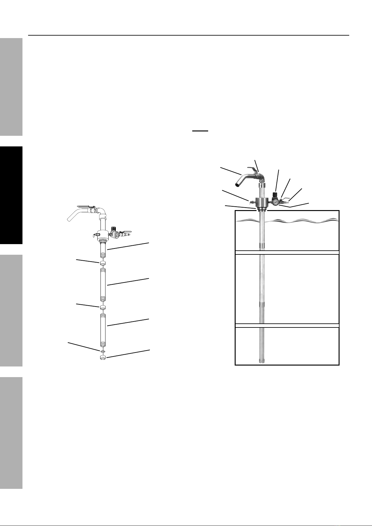
Components and Controls
Suction
Tube
Coupler
Inlet
Plug
Suction
Tube
Coupler
Suction
Tube A
Suction
Tube B
Suction
Tube C
Outlet
Tube
Air Inlet
Ball Valve
Air Pressure
Regulator
Pressure
Release
Valve
Pressure
Gauge
Air Quick
Coupler
Outlet
Ball Valve

Page 7For technical questions, please call 1-888-866-5797.Item 93755
SAFETYOPERATIONMAINTENANCE SETUP
Air Supply
TO PREVENT SERIOUS INJURY FROM EXPLOSION:
Use only clean, dry, regulated, compressed air to power this tool.
Do not use oxygen, carbon dioxide, combustible gases,
or any other bottled gas as a power source for this tool.
1. Incorporate a filter, regulator with pressure gauge,
in-line shutoff valve, and quick coupler for best
service, as shown on Figure A on page 8 and
Figure B on page 9. An in-line shutoff ball
valve is an important safety device because
it controls the air supply even if the air hose
is ruptured. The shutoff valve should be a
ball valve because it can be closed quickly.
2. Attach an air hose to the compressor's air outlet.
Connect the air hose to the air inlet of the tool.
Other components, such as a coupler plug
and quick coupler, will make operation
more efficient, but are not required.
WARNING! TO PREVENT SERIOUS INJURY
FROM ACCIDENTAL OPERATION:
Do not install a female quick coupler on the tool.
Such a coupler contains an air valve that will
allow the air tool to retain pressure and operate
accidentally after the air supply is disconnected.
Note: Air flow, and therefore tool performance,
can be hindered by undersized air supply components.
The air hose must be long enough to reach
the work area with enough extra length to
allow free movement while working.
3. Turn the tool's throttle or switch to the off position;
refer to Operation section for description of controls.
4. Close the in-line shutoff valve between
the compressor and the tool.
5. Turn on the air compressor according to
the manufacturer's directions and allow it
to build up pressure until it cycles off.
6. Adjust the air compressor's output regulator
so that the air output is enough to properly
power the tool, but the output will not exceed
the tool's maximum air pressure at any time.
Adjust the pressure gradually, while checking the
air output gauge to set the right pressure range.
7. Inspect the air connections for leaks.
Repair any leaks found.
8. If the tool will not be used at this time, turn off
and detach the air supply, safely discharge
any residual air pressure, and release
the throttle and/or turn the switch to its off
position to prevent accidental operation.
9. Residual air pressure should not be present
after the tool is disconnected from the air supply.
However, it is a good safety measure to
attempt to discharge the tool in a safe fashion
after disconnecting to ensure that the tool
is disconnected and not powered.

Page 8 For technical questions, please call 1-888-866-5797. Item 93755
SAFETY OPERATION MAINTENANCESETUP
Figure A: Portable Air Supply Setup
G
A
E
E
H
F
B
Non-lubricated
Tools
Lubricated
Tools
A
B
C
C
DA
Description Function
A Air Hose Connects air to tool
B Filter Prevents dirt and condensation from damaging tool or workpiece
C Regulator Adjusts air pressure to tool
D Lubricator (optional) For air tool lubrication
E Coupler and Plug Provides quick connection and release
F Leader Hose (optional) Increases coupler life
G Air Cleaner / Dryer (optional) Prevents water vapor from damaging workpiece
H Air Adjusting Valve (optional) For fine tuning airflow at tool

Page 9For technical questions, please call 1-888-866-5797.Item 93755
SAFETYOPERATIONMAINTENANCE SETUP
Figure B: Stationary Air Supply Setup
N
L
L O
M
C
C
Non-lubricated Tools
Lubricated
Tools
H
I
I
J
JKH
F
G
E
Slope
F
F
B
B
A
A
CD
Description Function
A Vibration Pads For noise and vibration reduction
B Anchor Bolts Secures air compressor in place
C Ball Valve Isolates sections of system for maintenance
D Isolation Hose For vibration reduction
E Main Air Line - 3/4″minimum recommended Distributes air to branch lines
F Ball Valve To drain moisture from system
G Branch Air Line -1/2″minimum recommended Brings air to point of use
H Air Hose Connects air to tool
I Filter Prevents dirt and condensation from damaging tool or workpiece
J Regulator Adjusts air pressure to tool
K Lubricator (optional) For air tool lubrication
L Coupler and Plug Provides quick connection and release
M Leader Hose (optional) Increases coupler life
N Air Cleaner / Dryer (optional) Prevents water vapor from damaging workpiece
O Air Adjusting Valve (optional) For fine tuning airflow at tool
Page 10 For technical questions, please call 1-888-866-5797. Item 93755
SAFETY OPERATION MAINTENANCESETUP
Assembly
1. Wrap 4" of pipe sealer tape (not included) around
the male threads located on the lower section of
Suction Tube A (5). Then firmly screw a Suction
Tube Coupler (7) onto the Suction Tube.
2. Wrap 4" of pipe sealer tape around the male
threads on both ends of Suction Tube B (6). Then
firmly screw one end of Suction Tube B into the
Suction Tube Coupler attached to Suction Tube A.
3. Firmly screw the remaining Suction Tube Coupler
onto the lower section of Suction Tube B.
4. Wrap 4" of pipe sealer tape around the
male threads on both ends of the remaining
Suction Tube C (8). Then firmly screw one
end of Suction Tube C into the Suction Tube
Coupler attached to Suction Tube B.
5. Insert the Oil Filter (9) into the Inlet Plug (10).
Then, firmly screw the Inlet Plug onto the
lower section of Suction Tube C.
Inlet Plug
(10)
Oil Filter
(9)
Suction Tube
Coupler (7)
Suction
Tube A
(5)
Suction Tube
Coupler (7)
Suction
Tube B
(6)
Suction
Tube C
(8)
Figure C: Suction Tube Setup
6. Unscrew and remove the large bung from
the barrel of liquid to be extracted.
7. Insert the lower section of the Drum Extractor
through the bung of the barrel. Then
firmly screw the Drum Extractor into
the female threads of the bung.
8. To adjust the length of the tube in the
barrel, grasp the regulator assembly
and twist it up or down on the pipe.
Note: The male threads of the Drum Extractor
are designed to fit a 1-1/2" or 2" diameter
bung. Refer to Figure D: Barrel Setup.
Barrel
(not included)
Outlet
Tube Air Inlet Ball Valve
Regulator
Pressure
Gauge
Air Quick Coupler
Outlet Ball Valve
Pressure
Release
Valve
1-1/2" ~ 2"
Diameter
Threads
Figure D: Barrel Setup

Page 11For technical questions, please call 1-888-866-5797.Item 93755
SAFETYOPERATIONMAINTENANCE SETUP
Operating Instructions
Read the ENTIRE IMPORTANT SAFETY INFORMATION section at the beginning of this
manual including all text under subheadings therein before set up or use of this product.
TO PREVENT SERIOUS INJURY:
Do not adjust or tamper with any control or component in a way not specifically explained within
this manual. Improper adjustment can result in tool failure or other serious hazards.
Inspect Drum Extractor before use, looking for damaged, loose, and
missing parts. If any problems are found, do not use unit until repaired.
Follow all guidelines regarding materials being extracted, including MSDS instructions and EPA regulations.
Note: For additional information regarding the parts listed in the following pages,
refer to Parts List and Diagram on page 14.
General Operating Instructions
CAUTION: Do not use the Drum Extractor on damaged
or rusted barrels. Barrel must have a sealed lid. This
unit pressurizes the barrel to extract liquid and will only
operate properly and safely on closed, sealed barrels.
1. With the Air Inlet Ball Valve in the closed
position, connect one end of an air hose to the
Air Quick Coupler on the Drum Extractor.
2. Connect the other end of the air hose to an
air compressor. Refer to Figure A: Portable
Air Supply Setup on page 8 and Figure B:
Stationary Air Supply Setup on page 9
for typical air supply setup options.
3. Turn on the air compressor, and set its
regulator to 10 PSI. Do not exceed 10 PSI.
4. Set the Regulator on the Drum Extractor up to
10 PSI. Stay within air pressure capacity.
Do not operate the Extractor above 10 PSI.
Note: The rate of flow of the liquid being extracted
depends on its fluid viscosity. To adjust the
Regulator’s PSI and alter the rate of flow, lift up
and twist the Knob on the Regulator. Then, push
in on the Knob. To increase air pressure, turn the
Knob clockwise. To decrease air pressure, turn the
Knob counterclockwise. Do not exceed 10 PSI.
5. Open the Outlet Ball Valve first, then open
the Air Inlet Ball Valve to extract liquid through
the Outlet Tube into an appropriate container.
6. If the tool requires more force to accomplish
the task, verify that the tool receives sufficient,
unobstructed airflow (CFM) and increase
the pressure (PSI) output of the regulator up
to 10 PSI, the maximum air pressure rating
of this tool. Do not exceed 10 PSI.
7. To stop the flow of liquid close the Air Inlet Ball
Valve first, then close the Outlet Ball Valve.
8. When finished, close the Air Inlet Ball Valve and
turn off the air compressor. Hold an appropriate
container under the Outlet Tube to catch residual
liquid and open the Air Inlet Ball Valve again to
release any compressed air in the Extractor.
Turn the Regulator to its lowest setting. Close
the Air Inlet Ball Valve and Outlet Ball Valve.
Disconnect the air hose from the Drum Extractor.
9. Dispose of the collected liquid in accordance
with all applicable local, state and federal laws.
10. If necessary, unscrew and remove the
Drum Extractor from the barrel. Replace the bung
on the barrel. Wipe the tool dry and store in a
clean, dry, safe location out of reach of children.

Page 12 For technical questions, please call 1-888-866-5797. Item 93755
SAFETY OPERATION MAINTENANCESETUP
Maintenance
Procedures not specifically explained in this manual must
be performed only by a qualified technician.
TO PREVENT SERIOUS INJURY FROM ACCIDENTAL OPERATION:
Turn off the tool, detach the air supply, safely discharge any residual air pressure
in the tool, and release the throttle and/or turn the switch to its off position before
performing any inspection, maintenance, or cleaning procedures.
TO PREVENT SERIOUS INJURY FROM TOOL FAILURE:
Do not use damaged equipment. If abnormal noise, vibration,
or leaking air occurs, have the problem corrected before further use.
Follow all guidelines regarding materials being extracted,
including MSDS instructions and EPA regulations.
Cleaning, Maintenance, and Lubrication
Note: These procedures are in addition to the regular checks and maintenance
explained as part of the regular operation of the air-operated tool.
1. BEFORE EACH USE, inspect the general
condition of the Drum Extractor. Check for:
• loose hardware or housing
• misalignment or binding of moving parts
• cracked or broken parts
• any other condition that may
affect its safe operation.
2. AFTER EACH USE, clean the exterior of
the Drum Extractor, wipe with a clean, damp
cloth using a mild detergent or mild solvent.
Do not immerse the tool in liquids.
3. To clean the interior of the Drum Extractor,
place the lower section into a container of mild
detergent or mild solvent. Connect the Extractor
to an air compressor to force detergent or
solvent through the tool and into an appropriate
waste container until the detergent or solvent
flow is clean. When finished, disconnect the air
compressor, releasing all remaining pressure
from the tool. Remove the Extractor from
the detergent/solvent and dry thoroughly.
4. Daily - Air Supply Maintenance:
Every day, maintain the air supply according
to the component manufacturers' instructions.
Drain the moisture filter regularly.
Performing routine air supply maintenance
will allow the tool to operate more safely
and will also reduce wear on the tool.
5. Store the Drum Extractor in a safe, dry,
clean location out of reach of children.

Page 13For technical questions, please call 1-888-866-5797.Item 93755
SAFETYOPERATIONMAINTENANCE SETUP
Troubleshooting
Problem Possible Causes Likely Solutions
Decreased output. 1. Not enough air pressure and/or
air flow.
2. Obstructed valve.
3. Air leaking from loose housing.
4. Mechanism contaminated.
5. Liquid is too viscous.
6. Blockage in barrel or Extractor.
1. Check for loose connections and make sure that
air supply is providing enough air flow (CFM)
at required pressure (PSI) to the tool's air inlet.
Do not exceed maximum air pressure.
2. Clean around valve to ensure free movement.
3. Make sure housing is properly assembled and tight.
4. Have qualified technician clean and
lubricate mechanism. Install in-line filter in
air supply as stated in Setup: Air Supply.
5. Make sure the Air Regulator of the Drum
Extractor is adjusted to compensate for
the viscosity of the liquid being extracted.
Do not exceed maximum air pressure.
6. Remove Drum Extractor from the barrel and check for
blockages in the system and remove any obstructions.
Severe air leakage.
(Slight air leakage
is normal,
especially on
older tools.)
1. Cross-threaded housing
components.
2. Loose housing.
3. Damaged valve or housing.
4. Dirty, worn or damaged valve.
1. Check for incorrect alignment and uneven gaps.
If cross-threaded, disassemble and
replace damaged parts before use.
2. Tighten housing assembly.
If housing cannot tighten properly,
internal parts may be misaligned. Technician needs
to disassemble tool, align parts and reassemble.
3. Replace damaged components.
4. Clean or replace valve assembly.
Housing heats
during use.
Worn parts. Have qualified technician inspect internal
mechanism and replace parts as needed.
Follow all safety precautions whenever diagnosing or servicing the tool.
Disconnect air supply before service.

Page 14 For technical questions, please call 1-888-866-5797. Item 93755
SAFETY OPERATION MAINTENANCESETUP
Parts List and Diagram
PLEASE READ THE FOLLOWING CAREFULLY
THE MANUFACTURER AND/OR DISTRIBUTOR HAS PROVIDED THE PARTS LIST AND ASSEMBLY DIAGRAM
IN THIS MANUAL AS A REFERENCE TOOL ONLY. NEITHER THE MANUFACTURER OR DISTRIBUTOR
MAKES ANY REPRESENTATION OR WARRANTY OF ANY KIND TO THE BUYER THAT HE OR SHE IS
QUALIFIED TO MAKE ANY REPAIRS TO THE PRODUCT, OR THAT HE OR SHE IS QUALIFIED TO REPLACE
ANY PARTS OF THE PRODUCT. IN FACT, THE MANUFACTURER AND/OR DISTRIBUTOR EXPRESSLY
STATES THAT ALL REPAIRS AND PARTS REPLACEMENTS SHOULD BE UNDERTAKEN BY CERTIFIED AND
LICENSED TECHNICIANS, AND NOT BY THE BUYER. THE BUYER ASSUMES ALL RISK AND LIABILITY
ARISING OUT OF HIS OR HER REPAIRS TO THE ORIGINAL PRODUCT OR REPLACEMENT PARTS
THERETO, OR ARISING OUT OF HIS OR HER INSTALLATION OF REPLACEMENT PARTS THERETO.
Parts List
Record Product's Serial Number Here:
Note: If product has no serial number, record month and year of purchase instead.
Note: Some parts are listed and shown for illustration purposes only, and are not available
individually as replacement parts. Specify UPC 193175451507 when ordering parts.
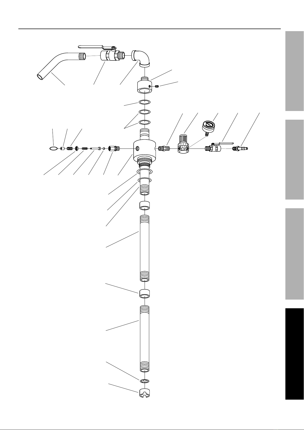
Part Description Qty
1Pressure Gauge 1
2 Air Quick Coupler 1
3 Air Inlet Ball Valve 1
4 Air Pressure Regulator 1
5 Suction Tube A 1
6 Suction Tube B 1
7 Suction Tube Coupler 2
8 Suction Tube C 1
9 Oil Filter 1
10 Inlet Plug 1
11 O-Ring 1
12 O-Ring 1
13 Housing 1
14 Valve Body 1
15 Control Bolt 1
Part Description Qty
16 Lock Nut 1
17 Valve Core 1
18 Spring 1
19 Pull Ring 1
20 Valve Cover 1
21 Outlet Tube 1
22 Outlet Ball Valve 1
23 Elbow 1
24 Swivel Coupler 1
25 O-Ring 1
26 O-Ring 2
27 Screw Cap 1
28 Coupler 1
29 Valve Core 1
Page 15For technical questions, please call 1-888-866-5797.Item 93755
SAFETYOPERATIONMAINTENANCE SETUP
Assembly Diagram
28 4 1 3 2
5
6
7
8
9
10
12
11
16 18 29 17 14 13
19 20 15
21 22 23
24
27
25
26

Limited 90 Day Warranty
Harbor Freight Tools Co. makes every effort to assure that its products meet high quality and durability standards,
and warrants to the original purchaser that this product is free from defects in materials and workmanship for the
period of 90 days from the date of purchase. This warranty does not apply to damage due directly or indirectly,
to misuse, abuse, negligence or accidents, repairs or alterations outside our facilities, criminal activity, improper
installation, normal wear and tear, or to lack of maintenance. We shall in no event be liable for death, injuries
to persons or property, or for incidental, contingent, special or consequential damages arising from the use of
our product. Some states do not allow the exclusion or limitation of incidental or consequential damages, so the
above limitation of exclusion may not apply to you. THIS WARRANTY IS EXPRESSLY IN LIEU OF ALL OTHER
WARRANTIES, EXPRESS OR IMPLIED, INCLUDING THE WARRANTIES OF MERCHANTABILITY AND FITNESS.
To take advantage of this warranty, the product or part must be returned to us with transportation charges
prepaid. Proof of purchase date and an explanation of the complaint must accompany the merchandise.
If our inspection verifies the defect, we will either repair or replace the product at our election or we may
elect to refund the purchase price if we cannot readily and quickly provide you with a replacement. We will
return repaired products at our expense, but if we determine there is no defect, or that the defect resulted
from causes not within the scope of our warranty, then you must bear the cost of returning the product.
This warranty gives you specific legal rights and you may also have other rights which vary from state to state.
26677 Agoura Road • Calabasas, CA 91302 • 1-888-866-5797
Other manuals for 93755
1
Table of contents
Other Central Pneumatic Scrubber manuals


