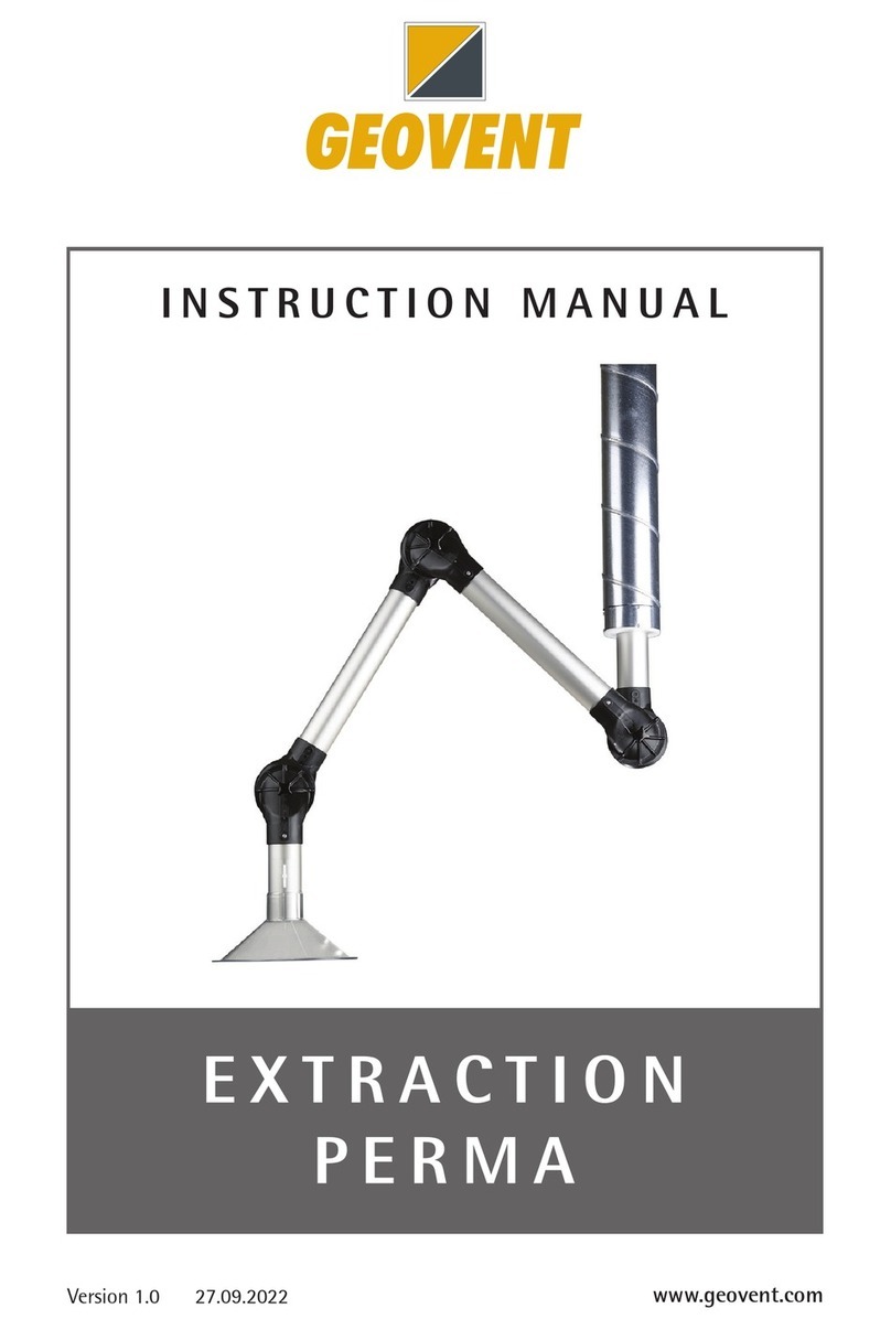
Geovent ASA-2 User manual

ASA-2 arm
ø80, ø100, ø125, ø160 & ø200
UK
D
DK
Instruction manual
Instruktionsmanual
Bedienungsanleitung

Instruction Manual ASA-2 Arm
Contents
1.0 General safety precautions
1.1 Danger
1.2 Field of application
1.3 Technical data
1.4 Construction – table of dimensions
2.0 Installation
2.1 Optional equipment
2.2 Connection
2.3 Trial run – exact adjustment
3.0 User instruction – application
4.0 Maintenance
5.0 Liability
6.0 Declaration of conformity
1.0 General safety precautions
IMPORTANT – Please study all the instructions
before mounting and commissioning.
Please keep these instructions in a safe place and
instruct all users in the function and operation of
the product.
Do not dismantle any factory-mounted parts,
since it impedes the commissioning of the
equipment.
All electrical installations must be carried out by
an authorised electrician.
1.1 Danger
Explosive media – The Extraction Arm is not
suitable for the extraction of aluminium dust, flour,
textile dust nor for sawdust or other media, which
are connected with danger of explosion, without
specific approval from Geovent A/S.
Placing the hand between the gas spring and the
carrying arm could involve a risk of mutilation.
Boring in the gas spring or other ways of
puncturing it is deadly dangerous.
1.2 Field of application
The GEOVENT ASA-2 Arm is the ideal Extraction
Arm for the extraction of welding smoke, grinding
dust, fumes, etc., where the well-being of the
operator is in focus with regard to lightness,
ergonomics and efficiency of the Arm.
The Extraction Arm is not suitable for the
extraction of aluminium dust, flour, textile dust nor
sawdust or other media, which are connected with
danger of explosion, without specific approval
from Geovent A/S.
The hose may be damaged and leaky via outer
loads, e.g. by a screw driver. Avoid such load in
order to safeguard a long life.
1.3 Technical data
Recommended flow area
Hose dimension:
Ø80
Ø100
Ø125
Ø160
Ø200
Volume of air:
200-300 m³/h
300-450 m³/h
450-800 m³/h
800-1200 m³/h
1200-2000 m³/h
Length: 2 or 3 m
By means of an extension arm
up to: 7 m
Hose max. temp. (depends on
the type)
Up to 150°C
1.4 Construction
Wall bracket: Steel bracket, powder enamelled
yellow in RAL 1007. The rotary joints can rotate
270°.
Funnel: Light-weight aluminium funnel ø80, 100,
125, 160 or 200 mm. The Ø160 and the ø200 mm

Instruction Manual ASA-2 Arm
funnels are supplied with integrated handle. The
funnel is powder enamelled in RAL 1007. May be
rotated in all possible positions.
Arms and friction joint: 25x25 mm aluminium pipe,
connected via knee joints with friction discs and
disc springs. The inner reinforced arm is executed
in 30x30 mm electro galvanised steel pipe and
supplied with a gas damper.
2.0 Installation
The ASA-2 Arm is supplied partly assembled.
Depending on model, it may consist of 1 partly
assembled carrying arm, 1 funnel and 1 set of
hose with clamp. The centre part of the carrying
arm is to be turned around and fastened with two
17 mm fixed spanners.
Before mounting the Arm, please make sure that
the optimum working area is selected. Is there
space enough for the satisfactory utilisation of the
Arm? What about connection possibilities for
piping and automatics? The optimum installation
height is then to be selected in accordance with
the table below:
Recommended installation height ASA-2 Arm:
2 m 2500 mm
3 m 2500 mm
4 m (incl. 1 m extension arm) 2500 mm
5,5 m (incl. 2.5 m extension arm) 2500 mm
7 m (Incl. 4 m extension arm) 2500 mm
Table of dimensions - Arm
Length A [mm] B [mm] D [mm] E [mm] F [mm]
2.0 m 920 680 206 120 200
3.0 m 1420 1180 206 120 200
Table of dimensions - funnel
Funnel C [mm] G [mm]
Ø80 180 178
Ø100 180 198
Ø125 180 223
Ø160 318 360
Ø200 318 360
Procedure:
1. The wall bracket is firmly attached to the wall
by means of 4 off 10mm bolts. (When using
the extension arm, please fix this bracket first
– refer to item 2.1)
2. Mount the Arm on the wall bracket with the
M16 bolt and friction discs. Make sure to
fasten it in such a way that the Arm is easily
rotated.
3. Mount the centre part by taking the supplied
M12 bolt through 3 disc springs, the alu half,
the friction disc, the other alu half and 3 disc
springs and fasten them with an M12 lock
nut. Tighten the joint so that the arm is easy
to rotate, however, still so much that it is self-
retentive in a lightly bent position.
4. Mount the funnel on the outer joint by taking
the supplied M8 bolt through 3 disc springs,
the alu half, the friction disc, the other alu half

Instruction Manual ASA-2 Arm
and the 3 disc springs and fasten them with
an M8 lock nut.
5. The hose is mounted on the funnel by
tightening the clamp around the funnel and
the hose. Now pull out the hose to max. so
that the least possible resistance is left in the
hose and fasten with the enclosed plastic
binders. Subsequently, the hose is mounted
on the branch pipe by means of the clamp.
2.1 Mounting of optional equipment
Mounting of extension arm
Start by fixing the extension arm to the wall, as
described in item 2.0 (applies to 1.0 and 2.0 m
extension arms). For the 2.5 and 4.0 m extension
arms, please fix the wall bracket first. (Refer to the
hole dimensions).
At 4 meters, every joint is assembled and then the
Arm is mounted. Next, the spiro pipe is fastened
to the extension arm by means of the enclosed
self-cutting screws. The part between the spiro
pipes is assembled by means of clamps and the
supplied hose.
Mounting of the damper
Is factory-mounted. Contact your dealer.
Mounting of light
The mounting of light and net should have been
taken care of by the factory. The connection is
made by extending the power cord, which is
attached inside the Arm and it is to be fixed on the
Arm. Next, the power cord is connected to the
transformer (24V Æ220V) which again is
connected to the mains.
Light specifications:
Type: Halogen
Power: 50 W 60°
Voltage: 12 V
Recommended trafo-power: 70 W
2.2 Power connection
For connection of various electrical components
(e.g. light sensor), please refer to the enclosed
documentation for the actual product.
The electrical installation is to be carried out by a
certified electrician.
2.3 Trial run – exact adjustment
After the final mounting, the ASA-2 Arm should be
adjusted to the typical working area, for optimum
utilisation of the Arm. Do so by adjusting the
rotary joints mentioned in item 2 by means of 2 off
17 mm fixed spanners.
3.0 User instruction – application
For normal use, the Arm is to be self-retentive in
the required position within the working area. The
bracket of the Arm supplies a 270° rotary working
area.
If the equipment has been correctly dimensioned,
the funnel of the Arm should be placed in vertical
position 300-500 mm over the blanks to be
welded. That is just above the pollutant. Thus up
to 99% of the polluting particles will be caught.

Instruction Manual ASA-2 Arm
Less optimal welding situation.
Always check that the correct volume of air is
extracted by the suction head/funnel.
The Arm does not work if …
- unauthorised parts have been mounted on the
Arm (e.g. power point on the funnel)
- the Arm is pushed towards the required
position. Instead, please move the Arm to the
required position and wait a moment until the
friction discs have locked the Arm. If this does
not work, please tighten the loose joint with
two 17 mm fixed spanners.
- something has been hung on the extension
arm. It is only meant to be capable of carrying
the weight of the actual Arm.
4.0 Maintenance
Periodic maintenance
•When it becomes difficult to position the Arm,
e.g. if it will not remain in the required position,
please adjust the movable joints (please refer
to item 2).
•Please check the condition of the hose, the
spring as well as the friction discs, and
exchange them if necessary. Please contact
your dealer in respect of spare parts.
At least once annually, the whole point extraction
plant should be overhauled by an authorised
serviceman.
5.0 Liability
Warranty
Geovent A/S grants a warranty for products,
which are defective, when it can be proved that
the defects are due to poor manufacture or
materials on the part of Geovent. The warranty
comprises remedial action (reparation or
exchange) until one year after date of shipment.
No claims can be made against Geovent A/S in
relation to loss of earnings or consequential loss
as a result of defects on products from Geovent.
Wear parts like hoses, etc. are not included in the
warranty.
User liability
In order for Geovent to be capable of granting the
declared warranty, the user/fitter must follow this
Instruction Manual in all respects.
Under no circumstances may the products be
changed in any way, without prior written
agreement with Geovent A/S.
6.0 Declaration of conformity
The manufacturer: GEOVENT A/S
HOVEDGADEN 86
DK-8831 LØGSTRUP
hereby declares that:
The products: Extraction Arms
Model: ASA-2 (ø80 to ø200)
have been manufactured in compliance with the
directions of the Directive Council of 14 June
1989 in common approximation to the legislation
of the member states regarding machine safety
(89/392/EEC amended by the directive
91/368/EEC) with special reference to appendix 1
in the Directive regarding basic health and safety
requirements in connection with the construction
and manufacturing of machinery.
GEOVENT A/S • HOVEDGADEN 86 • DK-8831
LØGSTRUP
Position: Managing Director
Name: Steen Molsen
Date: 19/02-02
Signature: ____________________________
Brevo B.V.
Dokwerkerstraat 3
2984 BJ Ridderkerk
Telefoon 0180-417344, Fax 0180-411563
Table of contents
Other Geovent Scrubber manuals
Popular Scrubber manuals by other brands

Polivac
Polivac GAZDA42 OPERATIONS MANUAL & TROUBLE SHOOTING GUIDE

Tennant
Tennant T2 manual

Advance acoustic
Advance acoustic 9084417010 Instructions for use - original instructions

Wetrok
Wetrok Durodisc LS operating instructions

CDA
CDA EVCK41 Installation, use and maintenance

BSX
BSX BSX400-DAF user manual