CENTRAL RESTAURANT PRODUCTS CPGM24 Guide

GAS GRIDDLE
MODEL
CPGM24, CPGM36, CPGM48
Installation, Operation & Parts Manual
2M-Z17577 Rev. A 06-2019
IL2697

2
2
These symbols are intended to alert the user to the presence of
important operating and maintenance instructions in the manual
accompanying the appliance.
RETAIN THIS MANUAL FOR FUTURE REFERENCE
NOTICE
Using any part other than genuine Star factory supplied parts relieves the
manufacturer of all liability.
Star reserves the right to change specifications and product design without
notice. Such revisions do not entitle the buyer to corresponding changes,
improvements, additions or replacements for previously purchased
equipment.
Due to periodic changes in designs, methods, procedures, policies and
regulations, the specifications contained in this sheet are subject to change
without notice. While Star International Holdings Inc., Company exercises
good faith efforts to provide information that is accurate, we are not
responsible for errors or omissions in information provided or conclusions
reached as a result of using the specifications. By using the information
provided, the user assumes all risks in connection with such use.
MAINTENANCE AND REPAIRS
Contact your local authorized service agent for service or required maintenance.
Please record the model number, serial number, voltage and purchase date in the area below and have it ready when
you call to ensure a faster service.
SAFETY SYMBOL
Model No.
Serial No.
Voltage
Purchase Date
Business 8:00 am to 4:30 p.m. Central Standard Time
Hours:
Telephone: (800) 264-7827
Fax: (314) 781-2714
E-mail [email protected]
Website: www.star-mfg.com
Service Help Desk
Authorized Service Agent Listing
Reference the listing provided with the unit
or
for an updated listing go to:
Website: www.star-mfg.com
E-mail [email protected]
Mailing Address: Star International Holdings Inc., Company
U.S.A
CAUTION WARNING
265 Hobson St.
Smithville, TN 37166

3
C
AB
IL2698
• Manual control with standing pilot for the budget-minded operator and experienced chefs who prefer the “feel”
of a manual control.
• Available in 24", 36" and 48" widths to meet your space and volume requirements.
• Ultra-smooth3/4"thickpolishedsteelplateforsuperiorheatdistribution,fastrecoveryandenergyefcient
operation.
• Custom designed 20,000 BTU aluminized steel U-shaped burner every 12” of cooking surface provide even
heat distribution
• Heavy-duty body construction with stainless steel front, bull nose and 4-1/2” high tapered splash guard.
• Spatula wide 3-1/4" front grease trough and grease chute for easier cleaning.
• Large 4-1/2 quart stainless steel grease drawer.
• Gasconvertibleintheeldwithconversionkitsupplied.UnitsareshippedNaturalGas.
• Heavy-duty4"adjustablelegstotyourcountertopline-uprequirements.
Central Products Gas Manual Griddles Specications
Model No Dimensions Controls BTU Cooking
Surface
Plate
Thickness
Approximate Weight
A B C Installed Shipping
CPGM24 24” (61.0 cm)
29”
(73.7 cm)
15 1/2”
(39.4 cm)
2 40,000 498 sq in
3/4”
165 lbs 175 lbs
CPGM36 36” (91.4 cm) 3 60,000 747 sq in 247 lbs 262 lbs
CPGM48 48” (121.9 cm) 4 80,000 996 sq in 330 lbs 350 llbs

4
GENERAL INSTALLATION DATA
This equipment is designed and sold for commercial use only by personnel trained and experienced
in its operation and is not sold for consumer use in and around the home nor for use directly by the
general public in food service locations.
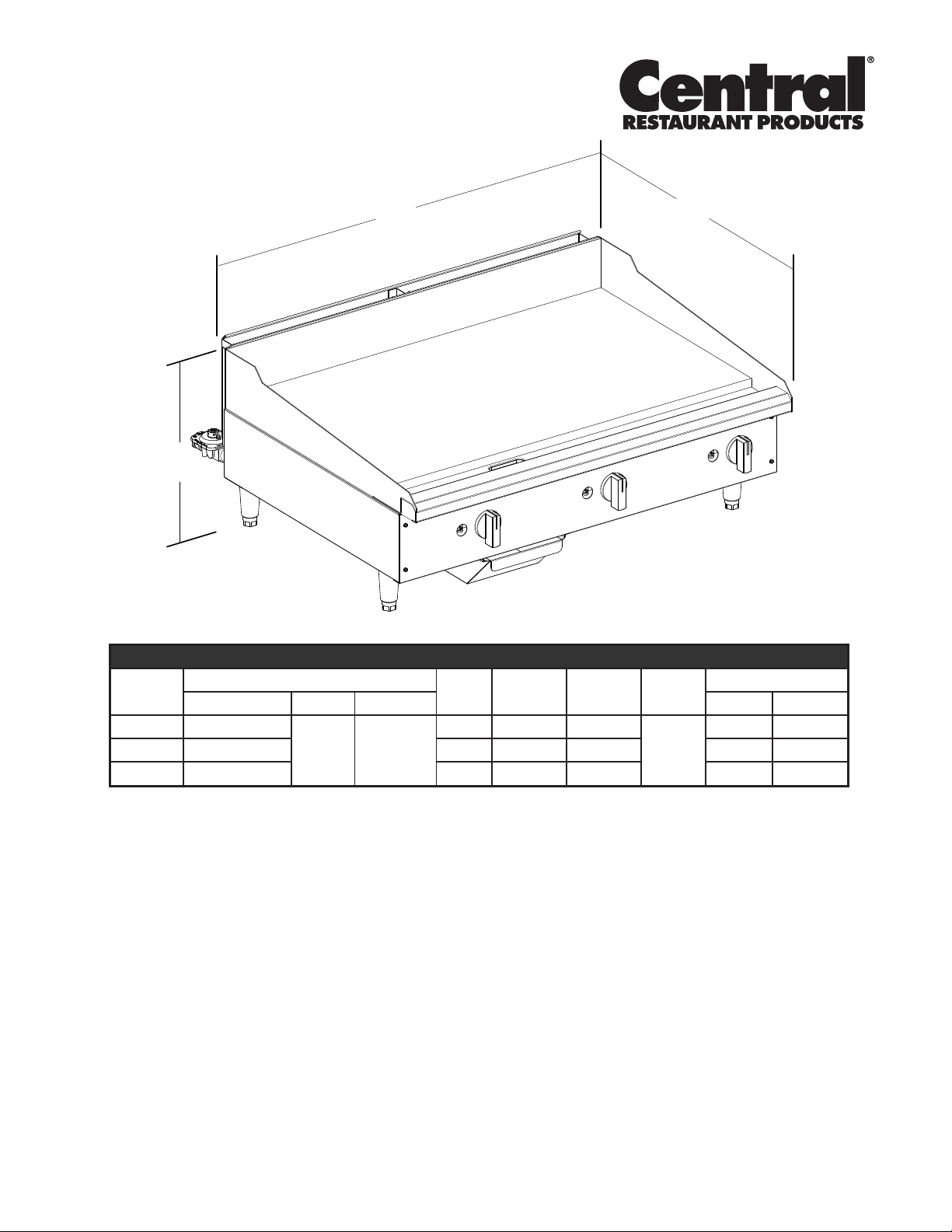
TheGustomodelgriddlesareequippedforusewiththetypesofgasspeciedonthenameplate.
All units are shipped from the factory for use with natural gas. The unit can easily be converted for
use on propane gas: See propane gas.
-IMPORTANT-
The installation of theAppliance should conform to the NATIONAL FUELGAS
CODE "ANSI Z223.1 - LATEST EDITION" AND ALL LOCAL GAS COMPANY
RULES AND REGULATIONS.
IN CANADA INSTALLATION SHALL BE IN ACCORDANCE WITH THE
CURRENT CAN/CGA-B149.1 NATURAL GAS INSTALLATION CODE OR
CAN/CGA-B149.2 PROPANE INSTALLATION CODE AND LOCAL CODES
WHERE APPLICABLE.
Improper installation, adjustment, alteration, service or maintenance can cause property
damage, injury or death. Read the installation, operating and maintenance instructions
thoroughly before installing or servicing the equipment.
For your safety, do not store or use gasoline or other ammable vapors and
liquids in the vicinity of this or any other appliance. Keep the appliance area
clear and free from combustibles.
This appliance, its pressure regulator and its individual shutoff valve must be disconnected from the
gas supply piping system during any pressure testing of that system at test pressures in excess of 1/2
PSIG (3.45KPA).
This appliance and its pressure regulator must be isolated from the gas supply piping system by
closing its individual manual shutoff valve during any pressure testing of the gas supply piping system
at test pressures equal to or less than 1/2 PSIG (3.45KPA). For your protection, we recommend a
qualiedinstallingagencyinstallthisappliance.Theyshouldbefamiliarwithgasinstallationsand
yourlocalgasrequirements.Inanycase,yourgascompanyshouldbecalledtoapprovethenal
installation. In addition, there should be posted, in a prominent location, detailed instructions to be
followed in the event the operator smells gas. Obtain the instructions from the local gas supplier.
For your safety, if you smell gas -
1. Do not touch electrical switches.
2. Extinguishanyopename.
3. Immediately call your gas company.
KEEP THE APPLIANCE AREA FREE AND CLEAR FROM COMBUSTIBLES.
CLEARANCE
For use on non-combustible countertops only.
Combustible and non-combustible material must be at least 48" (120cm) from the top of the appliance
and 6" (150mm) from the sides and back. Adequate clearance should also be provided for proper
operation and servicing.
AIR SUPPLY
Makecertainnottoobstructtheowofcombustionandventilationair.Provisionsforadequateair
supply must be furnished. The legs supplied with the unit must be installed. Make certain that air
intake openings in the bottom of the appliance are not obstructed. They are essential for proper
combustion and operation of the appliance.
CAUTION
CAUTION
CAUTION

5
EXHAUST CANOPY
It is essential that facilities be provided over the griddle to carry off fumes and gases. However, the
unitshouldnotbedirectlyconnectedtoaueorstack.
LEVELING UNIT
This griddle is supplied with (4) feet which must be screwed into the legs attached to the body. Level
unit by adjusting the (4) feet which have an adjustment of 1-3/4" (43.75mm) for accurate and perfect
lineupwithotherunits.Afterthegriddleisinitsnalposition,adjustthelegstocreate1/8inchslant
from back to front on the griddle plate. This will allow grease to run into the grease gutter and provide
the proper combustion air for the burners.
DO NOT INSTALL WITHOUT ATTACHING FEET - DO NOT REMOVE FEET.
GAS PIPING
Gaspipingshallbeofsuchsizeandsoinstalledastoprovideasupplyofgassufcienttomeet
the full gas input of the appliance. If the appliance is to be connected to existing piping, it shall be
checked to determine if it has adequate capacity. Joint compound shall be used sparingly and only
on the male threads of the pipe joints. Such compounds shall be resistant to the action of LP gases.
WARNING: Any loose dirt or metal particles which are allowed to enter the gas lines on this appliance
willdamagethevalveandaffectitsoperation.Wheninstallingthisappliance,allpipeandttingsmust
be free from loose dirt.
GAS PRESSURE REGULATOR
A convertible pressure regulator is provided with each griddle. It should be connected to the inlet pipe
at the rear of the unit. The gas supply line is then connected to it. It is shipped set for 6" (15.24cm)
water column manifold pressure for use with natural gas.
MANUAL SHUT-OFF VALVE
A manual shut-off valve should be installed upstream from the union and within 6 feet (1.829m) of this
appliance.
GAS CONVERSION
Thisgriddleisequippedwithxedoricehoodsandisshippedfromthefactoryforuseoneither
naturalorLPgas.Toconverttopropanegas,installtheburneroricehoods,locatedinthegrease
drawer,(NATorcesarenotincluded)asfollows:
1. Remove front panel by removing screws located on the front and the bottom.
2. Removetheburner(s)fromthe oricehood(s).Thisisaccomplishedbyremovingtheburner
mounting screw(s) and sliding the burner(s) off the hood(s).
3. Removenaturalgasoricehood(s)andinstallthepropane
hood(s) furnished.
4. Reinstall burner(s).
Note: CPGM series grills use a #47 drill orice for
natural gas and a #55 drill orice for propane.
5. Reinstall front panel.
6. Remove the slotted, or hex-threaded, plug from the
pressure regulator. Invert the plug and re-install. The
letters"LPorNAT"shouldnowbevisibleontheplug.LP
unitstheregulatorisnowsetfor10"(25.4cm)watercolumn,andNATunitstheregulatorisnow
set for 6" (15.24cm) water column.
7. For LP Gas, set manifold pressure to 10" (25.4cm) water column. A 1/8" pipe plug on the supply
pipe can be removed for attaching a pressure gauge.
CONNECTING GAS SUPPLY LINE
The gas inlet of the griddle is sealed at the factory to prevent entry of dirt. Do not remove this seal
until the actual connection is made to the gas supply line.
PLUG
IL1199
Natural
Regulator
Propane / LP

6
CHECKING FOR GAS LEAKS
Soap and water solution or other material acceptable for the purpose shall be used in locating gas
leakage.Matches,candleame,orothersourcesofignitionshallnotbeusedforthispurpose.
Check entire piping system for leaks.
LIGHTING INSTRUCTIONS
Whengriddleisrstlit,itwillsmokeuntilthepreservationoilsandimpuritiesareburnedoff.
1. Turn off main valve to unit and wait 5 minutes to clear gas.
2. Turn off all knobs and pilot valves.
3. Turn on main valve and light all pilots.
4. Turn burner knobs to desired setting.
5. To turn burners off, turn knobs off.
NOTE: The griddles are equipped with standing pilots and should be lit immediately after
the gas is turned on.
Pilotamescanbelitandobservedthroughthefrontpanelviewports.However,bestaccessfor
lighting the pilot is from the bottom of the unit just behind the center wall.
PILOT LIGHT REGULATION
Adjustpilotlightamesassmallaspossible,buthighenoughtolightburnerimmediatelywhenburner
valve is turned on high.
BURNER ADJUSTMENT
1. Remove the front panel.
2. Turn burner valve knob to "HI" position.
3. Closetheairshutteronthefrontoftheburnertogiveasoftblueamehavingluminoustipsand
opentoapointwheretheyellowtipsdisappearandahardblueameisobtained.Repeatforall
burners.
BURNER OPERATION
To ignite burners, turn burner valve knob to "HI" position. Each burner is controlled by an individual
high-low,on-offvalve.Aninnitenumberoftemperaturesmaybeobtainedbyturningtheburnervalve
knob to any position between high and low. For overnight shutdown, turn the valves to the "OFF"
position.

7
SEASONING THE GRIDDLE HEATING SURFACE
(NON-CHROMIUM SURFACES)
Clean the griddle surface thoroughly. After the griddle has been thoroughly cleaned, it should be
seasoned to prevent food from sticking. Before using, and after each thorough scouring, season the
griddle heating surface in the following manner:
1. Turn the temperature control dial to 350°F (174.9°C).
2. Usingacleancloth,notaspatula,spreadathinlmofcookingoiloverthegriddlecookingsurface.
Thislmshouldremainonthehotgriddlesurface1/2hour.
3. Remove excess oil and wipe clean.
4. Applyanotherlmofcookingoiloverthehotcookingareaforanother1/2hourandagainremove
excess oil and wipe clean. The griddle surface should now be ready for use.
Even with careful seasoning food may, to some extent, stick to the griddle cooking
surface until griddle plate is "broken in."
GREASE PAN
A grease pan is located at the front and can be removed for cleaning from the front. This pan should
be checked and emptied when necessary.
EXERCISE EXTREME CARE IN HANDLING THE GREASE PAN CONTAINING HOT GREASE.
GRIDDLE CARE (NON-CHROMIUM AREAS)
Ittakesverylittletimeandefforttokeepthegriddleattractiveandperformingattopefciency.
If grease is permitted to accumulate, it will form a gummy cake and then carbonize into a hard
substancewhichisextremelydifculttoremove.Topreventthiscondition,thefollowingsuggestions
for cleanliness should be followed:
1. Aftereachuse,scrapethegriddlewithascraperorexiblespatulatoremoveexcessgreaseand
food. A waste drawer is provided for the scrapings. If there is an accumulation of burned on grease
and food, the griddle should be thoroughly scoured and reseasoned. Use pumice or griddle stone
while the griddle is warm. Do not use steel wool because of the danger of steel slivers getting into
the food.
2. Daily-use a clean cloth and good non-abrasive cleaner to clean the stainless steel body of the
griddle. Wipe the polished front with a soft cloth.
3. At least once a day remove the waste drawer and wash in the same way as an ordinary cooking
utensil. The drawer is removed by pulling forward, up and out.
CAUTION

8
Model: CPGM Gas Manual Control Griddle
SK2704, Rev. - 11/12/13
1
2
3
5
6
7
9
18
10
11
12
13
15
14
16
17
4
8
9
3
19
24
3
25
20
3
21
22
3
23

9
November 12, 2013, Rev -
Model: Central Products Manual Gas Griddle
Fig No. Part Number Description Qty Model
1G3-624304 1 CPGM24, 36, 48
2G5-Z4817 FLUE DIVIDER 1 CPGM36, 48
32C-8833 SCREW 8-18X1/2 HEX
STL NP
44 CPGM24
45 CPGM36
58 CPGM48
4
G5-Z4812 FLUE 24”
1
CPGM24
G5-Z4813 FLUE 36” CPGM36
G5-Z4814 FLUE 48” CPGM48
52C-Z2893 NUT 10-24 HEX STL
ZP
6 CPGM15, 24
8 CPGM36, 48
6
G3-Z5953
REAR PANEL 1
CPGM24
G3-Z5955 CPGM36
G3-Z5957 CPGM48
7 G3-624302 LINER ASSY LEFT 1 CPGM24
8G3-624303 LINER ASSY RIGHT 1 CPGM24
9G3-Z5945 SIDE PANEL LT/RT 2 CPGM24
10 2J-Z0792 REGULATOR 1 CPGM24
11
2K-Z5962
MANIFOLD 1
CPGM24
2K-Z5964 CPGM36
2K-Z5966 CPGM48
12 2F-Z5949 BURNER
2 CPGM24
3 CPGM36
4 CPGM48
13 2V-Z6647 PILOT TUBE CUT 4 1/4
2 CPGM24
3 CPGM36
4 CPGM48
14
2J-Y7216 HOOD BURNER #47
NAT
2 CPGM24
3 CPGM36
4 CPGM48
2J-Y7250 ORIFICE #55 LP
GRIDDLE
2 CPGM24
3 CPGM36
4 CPGM48
15 2V-6671 VALVE-LINCOLN
BRASS#3817
2 CPGM24
3 CPGM36
4 CPGM48
16 2V-Y8832 VALVE-MANUAL GAS
2CPGM24
3 CPGM36
4 CPGM48
17 2P-1453 PLUG-PIPE 1/8NPT
SQ HD 1 CPGM24
18 2A-Z5942 FOOT, 1/2-13 X 4”L. 4 CPGM24
19
G3-Z5915
CENTER WALL 1
CPGM24
G3-Z5925 CPGM36
G3-Z5935 CPGM48
Model: Central Products Manual Gas Griddle
Fig No. Part Number Description Qty Model
20 G3-Z5946 BURNER COVER GAS
2 CPGM24
3 CPGM36
4 CPGM48
21
G3-Z15867
FRONT PANEL 1
CPGM24
G3-Z15868 CPGM36
G3-Z15869 CPGM48
22
G3-Z5919
BAFFLE 1
CPGM24
G3-Z5929 CPGM36
G3-Z5939 CPGM48
23 2R-W498 KNOB-RED
2 CPGM24
3 CPGM36
4 CPGM48
24 G3-Z6036 DRAWER SLIDE 2 CPGM24
25 G3-Y7046 GREASE DRWR
GRIDDLE 1 CPGM24

10

11

This manual suits for next models
2
Table of contents