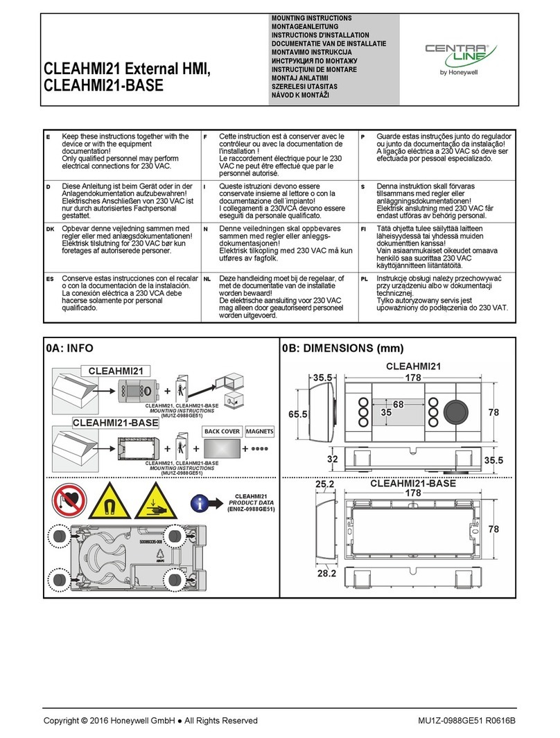
CentraLine CLEAHMI21 Operation manual

CLEAHMI21 External HMI Product Data
® U.S. Registered Trademark
Copyright © 2018 Honeywell Inc. • All Rights Reserved EN0Z-0988GE51 R1018
GENERAL
The CLEAHMI21 External HMI is a cost effective, versatile
mountable HMI for those EAGLE and EAGLEHAWK NX
controllers not equipped with a built-in HMI.
The CLEAHMI21 represents a network-independent,
comprehensive, and cost-effective operating option.
The CLEAHMI21 can be connected and used with the
following EAGLE / EAGLEHAWK NX controllers:
CLEA2000B31;
CLEA2014B31;
CLEA2014B32;
CLEA2026B31;
CLAXEHxxND100A;
CLAXEHSERIESxxND.
FEATURES
Local language operation: The CLEAHMI21 allows the
EAGLE controller to be operated in the following
languages: English, German, French, Italian, Spanish,
Greek, Norwegian, Finnish, Danish, Russian, Ukrainian,
and Czech. The default language can be pre-selected, and
also changed online.
In combination with the EAGLEHAWK NX, the languages
displayed on the CLEAHMI21 depend upon the languages
set up (using COACH NX) in the station which the
EAGLEHAWK NX is running.
Reduced cost for service, operation and maintenance
Maintenance or upgrade of Operator Interface Software is
superfluous because it resides in the EAGLE /
EAGLEHAWK NX controller, itself (single-source principle).
Application- or user-oriented operation: A configurable
start-screen allows for viewing custom fast access lists,
which can contain a random combination of data-point and
parameters. In combination with the EAGLEHAWK NX, the
start screen and the contents of its icons can be
customized (using COACH AX).
Intuitive push & turn wheel operation: Navigation,
selecting, and changing values is done using the push &
turn wheel, which conforms to industry standards.
Backlight with automatic time-out: The display backlight
will automatically turn ON upon pressing any key or
operating the push & turn wheel. It will automatically turn
OFF if none of the keys or the button are used for two
minutes. In combination with the EAGLEHAWK NX, the
Auto Logout Delay is adjustable.
Full display of long text information: Automatic left &
right scrolling enables lengthy texts to be viewed in their
entirety.
Versatile mounting options: The following mounting
options are available:
- Screw mounting into panel door cut-outs;
- Screw mounting onto panel doors or cabinets;
- Magnetic mounting onto metal surfaces;
- Screw mounting onto walls.
Standard Ethernet connection cable: A standard
Ethernet connection cable (max. length: 5 m) is used to
establish a connection between the RJ45 socket of the
CLEAHMI21 and the HMI port on the front of the EAGLE /
EAGLEHAWK NX controller. (NOTE: This is not a physical
Ethernet interface.)
Password protected access: Changing of values and
other data is restricted to registered users, by a multi-digit
password. In combination with the EAGLEHAWK NX, the
user access is fully embedded in the user management of
Niagara (COACH NX).
No extra power supply needed: Rather, the CLEAHMI21
derives needed energy from the controller via the standard
Ethernet connection cable.

CLEAHMI21 EXTERNAL HMI – PRODUCT DATA
EN0Z-0988GE51 R1018
2
HARDWARE INTERFACES
3
1
2
Fig. 1. CLEAHMI21 operating elements
Legend
1 LCD display
2 Six operating keys
3 Push & Turn button
The LCD display presents items for application-specific
system information, operator entries, and menus of functions.
It can show max. five lines of alphanumeric text with max. 20
characters per line.
The display's backlight is switched ON once an operating key
or the push & turn button is pressed, and switched OFF if no
operating key or button is used for 2 minutes.
The six operating keys consist of three fixed-function keys
(left) and three soft keys (right).
The push & turn button is used to navigate through menus
and lists; to highlight items (menu, list, option, value,
command symbol), and to adjust options (ON, OFF, etc.) and
values (temperature in °C, etc.).
MOUNTING
See also CLEAHMI21 External HMI – Mounting Instructions
(MU1Z-0988GE51) for details.
Cabling
4 4
3
1 2
Fig. 2. Rear view of CLEAHMI21, with connector cable
Legend
1 RJ45 socket for connection cable (see also WARNING
in section "Electrical Data" on pg. 4)
2 Cable guide for strain relief
3 Cable outlets
4 Screw holes (for mounting into panel doors)
Magnetic Mounting onto Metal Surfaces
For magnetic mounting, proceed as follows:
1. Remove the cover (see Fig. 3). Observe precautions
for handling electrostatic sensitive devices so as not to
damage the open printed wiring assembly.
C
A
B
Fig. 3. Removing cover
2. Insert the four magnets (incl. in delivery) (see Fig. 4).
Fig. 4. Inserting magnets into cover
3. Click the cover back into place (see Fig. 5).
A B
CLICK!
CLICK!
CLICK!
CLICK!
Fig. 5. Clicking cover back into place
4. Click the sub-base into place (see Fig. 6).
A
CLICK!
CLICK!
CLICK!
CLICK!
B
Fig. 6. Clicking sub-base into place
5. Plug the connection cable into the RJ45 socket and
loop through the cable guide for strain relief (see Fig.
7). The cable can exit the unit either through the upper
(B) or lower (B') outlet.
A
CLICK!
B
B
Fig. 7. Plugging cable and looping through guide
6. The unit can then be conveniently attached to any
metal surface (see Fig. 8).

CLEAHMI21 EXTERNAL HMI – PRODUCT DATA
EN0Z-0988GE51 R1018
3
Fig. 8. Wall mounting example (magnet option)
Alternatively, a metal plate (incl. in delivery) can be attached
for handheld use (see section "Handheld Option" below).
Handheld Option
In the case of the handheld option, proceed as described in
Fig. 3 to Fig. 7). Finally, attach the metal plate (see Fig. 9),
which completely covers the rear of the device.
Fig. 9. Attaching metal plate
Screw-Mounting into Panel Door Cut-Out
In the case of screw-mounting into a panel door cut-out (door
thickness: 1…2.5 mm), proceed as follows (see also Fig. 10):
1. Prepare a suitably dimensioned (157 X 58 mm) cut-out
with bore-holes (Ø 5 mm) at a distance of 166 mm
apart and slide the CLEAHMI21 into place.
2. Insert and fasten the two M4x6 (DIN 7985A) screws
(incl. in delivery).
3. Finally, plug the connection cable into the RJ45 socket
and loop it through the cable guide and cable outlet
(see Fig. 7).
166
157
58
2 2
1
Ø 5
1...2.5
Fig. 10. Panel door mounting (in mm)
Wall-Mounting (Screw Option)
In the case of wall-mounting with screws, proceed as follows
(see also Fig. 11 and Fig. 13):
1. Place two suitably dimensioned bore-holes (Ø 6 mm,
with a min. depth of 35 mm) at a distance of 164 mm
apart. Installation over a standard flush-mounted box
(max. 140 X 35 mm) is optional.
2. Insert the two dowels (incl. in delivery) until snug.
164
Ø 6
22
1 1
MAX. 140
MAX. 65
OPTIONAL
MIN. 35
Fig. 11. Wall-mounting (screw option), steps 1+2
3. Position the sub-base (with the connection cable
already in position through the upper [a'] or lower [a]
cable outlet or from the flush-mounted box [a'']) over
the two bore holes and insert and fasten using the two
screws (incl. in delivery).
a
a‘
a‘‘
Fig. 12. Positioning sub-base and cables
4. Finally, plug the connection cable into the RJ45
socket, loop it through the cable guide and cable outlet
(see Fig. 7), and then click the CLEAHMI21 into the
sub-base.
3 3
4
Fig. 13. Wall-mounting (screw option), steps 3+4

CLEAHMI21 EXTERNAL HMI – PRODUCT DATA
Manufactured for and on behalf of the Environmental and Combustion Controls Division of Honeywell Technologies Sàrl, Rolle, Z.A. La Pièce 16, Switzerland by its Authorized Representative:
CentraLine
Honeywell GmbH
Böblinger Strasse 17
71101 Schönaich, Germany
Phone +49 (0) 7031 637 845
Fax +49 (0) 7031 637 740
www.centraline.com
Subject to change without notice
EN0Z-0988GE51 R1018
SPECIFICATIONS
Table 1. Specifications
Ambient temperature 0 … 50 °C
Storage temperature -20 … +70 °C
Humidity 5 … 95% r.h. non-condensing
Dimensions See Fig. 14.
Degree of protection IP30 (panel- or wall-mounted)
Fire class V0
Shock protection Class II
Pollution degree 2
Installation Class 3
Software class Class A
Ball-pressure test
temperature Housing parts >75°C
Max. cable length 5 meters
Display
Dot matrix display, black & white,
160 x 80 dots, 5 lines with 20
characters
Electrical Data
Table 2. Electrical data
Power supply
From EAGLE / EAGLEHAWK NX
controller attached via standard
Ethernet cable to the RJ45 socket
of the CLEAHMI21
Increased power con-
sumption of EAGLE /
EAGLEHAWK NX
dc: max. 0.2 W;
ac: max. 0.2 VA
Increased heat
dissipation
max. 0.2 W at dc power supply
max. 0.2 W at ac power supply
WARNING
Risk of electric shock or equipment damage!
► It is prohibited to connect the RJ45 socket of the
CLEAHMI21 to a so-called PoE-enabled device ("Power
over Ethernet").
Mechanical Data
Housing Dimensions (L x B x T): 178 x 78 x 32 mm
Housing Material: ABS blend; flame retardant V0
Weight: 160 g (without sub-base, packaging)
Protection Class: IP 30 (panel- or wall-mounted)
Standards, Approvals, etc.
Device meets EN 60730-1, EN 60730-2-9
C UL® US-listed (file E340062)
ORDER NUMBERS
CLEAHMI21: External HMI and two M4x6 (DIN 7985A)
screws
CLEAHMI-BASE: Sub-base for wall-mounting and hand-held
use. Includes sub-base itself, two screws
(4x35 mm) and two dowels (6x30) for wall-
mounting, metal cover plate for convenient
handheld use, and four magnets for
mounting to metal surfaces.
DIMENSIONS
178
78
65.5
35.5
35.5
32
35
68
Fig. 14. Dimensions of CLEAHMI21 (in mm)
78
178
28.2
25.2
UPUP
Fig. 15. Dimensions of sub-base CLEAHMI-BASE (in mm)
Table of contents
Other CentraLine Monitor manuals
Popular Monitor manuals by other brands

MSI
MSI Optix MAG322CR (3DA5) manual
Panasonic
Panasonic TH-42PF30U operating instructions

Austin Hughes Electronics
Austin Hughes Electronics CyberView RP-1020QD brochure
NEC
NEC MD211G3 Installation & maintenance guide
ConMed
ConMed Linvatec VP4726 instruction manual
Defender Security
Defender Security DFR-MN-215HD quick start guide
