5
1 Implementation
Dear customers,
With the CENPAC product from Centrosolar AG, you have
acquired a strong, high-quality product.
This reliable complete system combines the benets of
a customized PV installation with the possibilities of an
immediately available standard solution and guarantees
optimal returns under nearly all conditions. It is also un-
complicated and quick to mount.
1.1 Notes on these instructions
If you have any questions on the installation or any com-
ponents of the installation, please contact your local Cen-
trosolar ofce.
Repairing and operating a PV installation require solid
expert knowledge. This is why all work on the installation
should only be carried out by correspondingly qualied
and authorized specialist personnel. Read these mount-
ing instructions carefully and attentively before installing
and commissioning the system. Keep the instructions in
an easily accessible place. The instructions are part of the
product, they only apply to the complete CENPAC sys-
tems of Centrosolar AG. Pay special attention to the notes
on safe use. Centrosolar will not accept liability for dam-
age arising due to failure to observe these instructions.
Please observe:
Ensure that the correct safety instructions are followed for
mounting and operation. Pay attention to the relevant gen-
eral preliminary remarks from Centrosolar AG, available at
www.centrosolar.com.
Failure to observe the requirements in these mounting in-
structions can lead to the exclusion of all guarantees, war-
ranties and product liability.
The following details, notes and recommendations for
action may not be complete and should be constantly
checked to see whether they are complete and up-to-date.
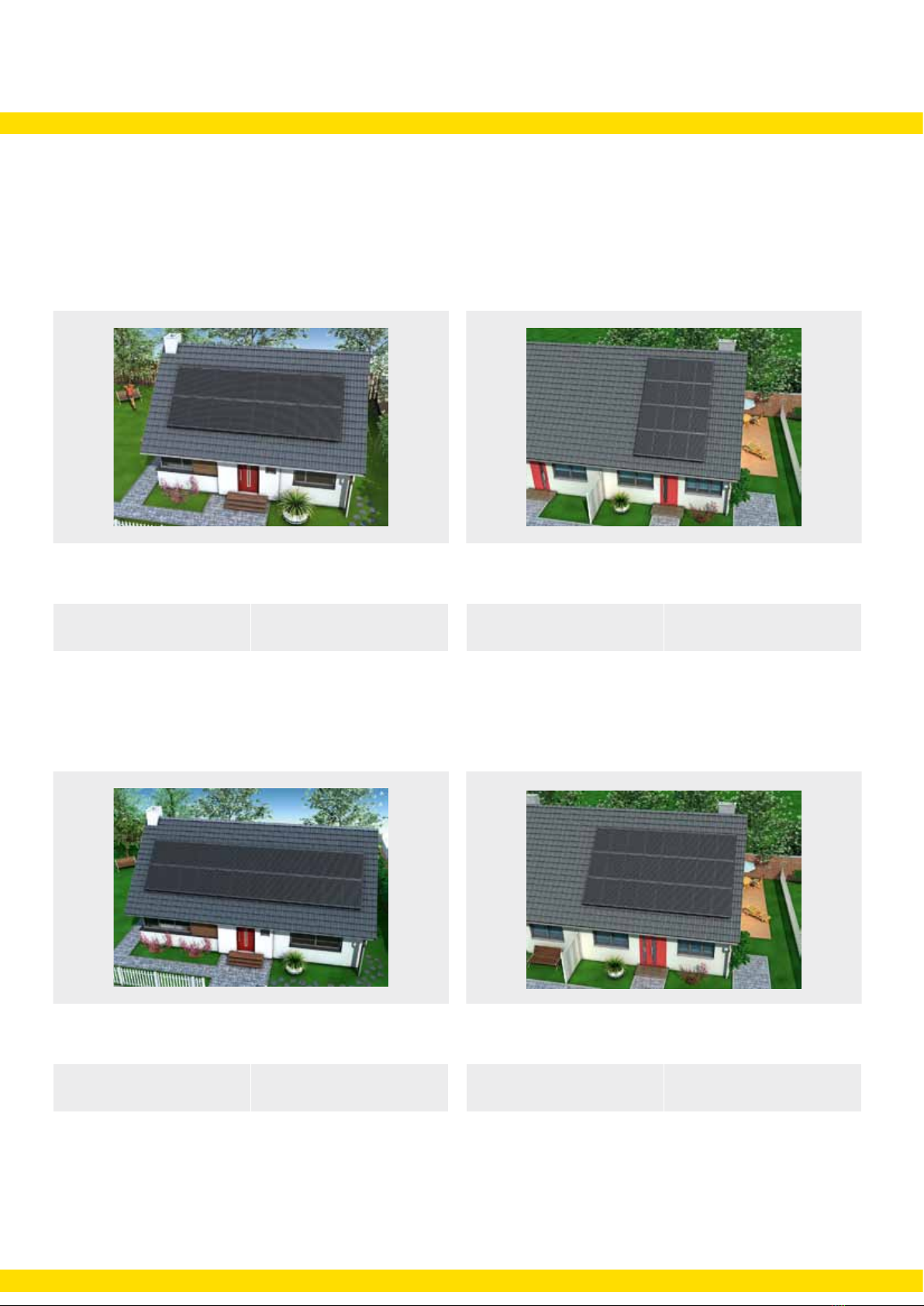
1.2 Description of the mounting system
The bearing capacity of the roof in connection with the as-
sembly of a Centrosolar photovoltaic installation and the
arrangement of the fastening points are to be shown in a
structural analysis for which the building owner is respon-
sible. There is no liability on the part of Centrosolar AG for
the structural suitability of the mounting construction.
The MS Constocc Excellent mounting system basically
consists of module support proles and 2-C groove pro-
les. Please see the summary of the mounting materials
(chapter 2) for an exact overview of the necessary com-
ponents. Assembly takes place in a cross-cross arrange-
ment. This is mechanically the most stable and safe in-
stallation of photovoltaic modules. The 2-C groove proles
are constructed vertically. The module support proles are
inlaid proles fastened horizontally onto the 2-C groove
proles.
All connecting elements and system parts are manufac-
tured from aluminium or stainless steel. The system pro-
les are delivered anodized in black.
For the suitable rafter conguration of your complete
CENPAC system, please see the rafter conguration
plans in the document folder.
In case of different rafter distances, congure your rafters
according to chapter 3.3 or contact your local Centrosolar
ofce.
Proper use
Check the delivery is complete by way of packing list and
parts list before commencing the mounting. Electrical in-
stallation work that may exceed the range of the safety
extra low voltage may only be carried out by electrotechni-
cal specialists.
The mounting system MS Constocc Excellent was de-
signed solely for holding the PV modules. Any other use
is regarded as improper. Proper use also includes adher-
ing to the mounting instructions Centrosolar AG cannot be
held liable for damage resulting from failure to observe the
mounting instructions, in particular, the safety instructions
or improper use of the product.