CEO Tech 50710 User manual

THANK YOU
We appreciate the trust and confidence you have placed in CE Tech through the purchase of this wall mounting
system. We strive to continually create quality products designed to enhance your home. Visit us online to see our
full line of products available for your home improvement needs. Thank you for choosing CE Tech!
Item #302-080
Model #50710
USE AND CARE GUIDE
FIXED LED / LCD TV WALL MOUNT
(UNIVERSAL MOUNTING PATTERN, FITS
VESA 100/200/300/400/600)
Questions, problems, missing parts? Before returning to the store,
call CE Tech Customer Service
8 a.m. - 6 p.m., EST, Monday - Friday
1-877-527-0313
HOMEDEPOT.COM

2
Table of Contents
Table of Contents ..................................2
Safety Information.................................2
Warranty.................................................3
Pre-Installation ......................................4
Installation .............................................6
Safety Information
Before you begin, carefully read and understand the
instructions in this manual. Please follow the
instructions in the order presented in this manual
and observe all warnings and cautions.
WARNING:A Warning alerts you to the
possibility of serious injury or death if you do
not follow the instructions.
CAUTION:A Caution alerts you to the
possibility of damage to or destruction of the
equipment if you do not follow the
corresponding instructions.
WARNING:Failure to provide adequate
structural strength for this component can
result in physical injury and/or damage to
equipment. It is the installer’s responsibility
to make sure the structure to which this
component is attached can support four
times the combined weight of all equipment.
Reinforce the structure as required before
installing the component.
WARNING:This wall or ceiling mount is
intended for use only with the maximum
weights indicated. Use with products heavier
than the maximum weights indicated may
result in collapse of the mount and its
accessories causing possible injury. This
mount has been tested to support 130 lbs.
(58.96 kgs). Do not exceed this weight.
WARNING:Safety measures must be
observed at all times during the installation of
this product. Use proper safety gear and tools
during the installation process to prevent
physical injury.
CAUTION:Do not install on a structure
that is prone to vibration, movement, or
chance of impact. Doing so could result in
damage to the flat panel display and/or
mounting surface.
CAUTION:Do not install near a heater,
fireplace, direct sunlight, or any other source
of direct heat.
Doing so could result in damage to the flat
panel display and could increase the risk of
fire.
Thismount hasbeen testedto
support a television with diagonal
screen sizesbetween 26in. and65 in.
(66 cm and165 cm) anda weight
up to 130 lbs. (58.96 kgs).
27.16" (689mm)
25.4" (645mm)
0.75"
(19.1mm)

3 HOMEDEPOT.COM
Please contact 1-877-527-0313 for further assistance.
Warranty
The manufacturer warrants that it will replace or repair this item, free of charge, at the manufacturer’s sole
discretion, should it prove defective in materials or workmanship. This warranty does not apply to:
□Normal wear and tear
□Friction damage
□Coating defects
□Defects caused by loosened screws, nuts, or bolts
□Improperly mounting the bracket to the wall
□Improperly installing the bracket to the display
□Failure to properly follow installation instructions
□Modification or repairs not made or authorized by the manufacturer
□Loading beyond permitted load
□Intentional misuse
Contact the Customer Service Team at 1-877-527-0313 or visit www.HomeDepot.com.
4
Pre-Installation
PLANNING INSTALLATION
Compare all parts in the package with the Hardware Included and Package Contents lists in this manual. If any part
is missing or damaged, do not install this wall mount system and call customer service at 1-877-527-0313 or visit
www.HomeDepot.com.
PLANNING WALL PLACEMENT
CAUTION:Ensure the wall you select is a
weight-bearing wall. Failure to observe this
precaution can result in serious physical
injury and/or property damage. Consult a
professional installer or contact customer
service if you have any questions.
When selecting a wall to mount your display, keep the following in mind:
□Select a place with easy access to power outlets, cable input sources, and connections for speakers and
accessories.
□Avoid direct sunlight, heat, and vibrations and do not place in direct flow of traffic.
□Select a weight-bearing wall. The wall must be able to safely support four times the combined load of the
equipment and all attached hardware and components.
PLANNING MOUNTING HEIGHT
The optimal viewing height is to center the display at eye level when seated. Many people consider this to be too low
for a wall mount, and commonly use the following rule for placement.
□Position the bottom of the display no higher than eye level when seated, and the top of the display no higher
than eye level when standing. Anything within these limits should normally provide a comfortable viewing
experience.
ENSURING WALL STABILITY
Carefully inspect the wall area you have selected. Examine the wall surface before you begin drilling.
WARNING:Do not drill near electrical wiring and water pipes.
CAUTION:Wood studs must be no smaller than 2 x 4 in. in size.
□For concrete walls, check for damaged or loose concrete and do not drill in those areas.
□For brick wall, never drill into the mortar between blocks.
□For wood studs, locate the wall studs and drill in the center of the stud.
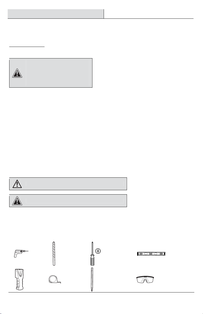
TOOLS REQUIRED (NOT INCLUDED IN THE PACKAGING)
Power drill
5/32 in. (4 mm)
wood drill bit or
¼ in. (6 mm) +
3/8 in. (10 mm)
masonry drill
bits
Phillips screwdriver Level
Stud finder
Tape measure Pencil Safety glasses
5 HOMEDEPOT.COM
Please contact 1-877-527-0313 for further assistance.
Pre-Installation (continued)
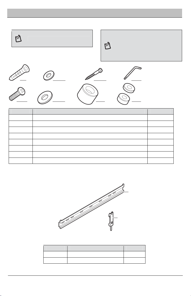
HARDWARE INCLUDED
NOTE: Hardware not shown to actual size.
NOTE: The hardware included is suitable for
mounting to walls made of brick, solid
concrete, or wood studs covered with drywall.
If your mounting situation is different, please
consult a qualified installer or contact customer
service at 1-877-527-0313 or visit
www.HomeDepot.com.
,
PACKAGE CONTENTS
Part Description Quantity
A Mounting rod 1
B Mounting bracket 2
AA BB DDCC
EE FF GG HH
A
B
Part Description Quantity
AA Nylon anchor 4
BB Lag washer 4
CC Lag bolt 4
DD Hex wrench 1
EE Screw (sizes M4x12, M5x15, M5x25, M6x16, M6x26, M8x20, M8x30) 4 each
FF Washer (sizes M4 and M6) 4 each
GG Knob 2
HH M8 spacer (sizes M8x2.5 and M8x8) 4 each

6
Installation
1
Identifying the screw
diameter to use
2
Identifying the screw length to
use
To ensure proper mounting of the brackets to your
TV, this mounting system includes several sizes
(M4, M5, M6, and M8) of screws (EE), washers (FF),
and spacers (HH) that can be used in various
combinations. Combinations are determined by the
back style of the TV (flat, curved, or recessed) and
the diameter and depth of those holes.
□Select the screw diameter to use by inserting
the various sized screws (M4, M5, M6, and M8)
into the mounting holes in the back of your TV.
□Insert a straw or toothpick into one of the
mounting holes on the back of your TV. If your TV
is curved or recessed, place the proper sized
spacer on top of one of the mounting holes first.
□Use a pencil to mark the depth of the mounting
hole.
□Determine the proper screw length to use by
comparing the mark with the various screws
provided.
CAUTION:
When the screw is longer than the
mark, choose a shorter screw.
M4
or or or
M5 M8
M6
Flat
Curved
Recessed
Correct
Incorrect

7 HOMEDEPOT.COM
Please contact 1-877-527-0313 for further assistance.
Installation (continued)
3 Installing the wall plate
(concrete/brick wall) 4Installing the wall plate
(wood stud)
If you are installing this mounting system in wood
studs, proceed to step 4.
CAUTION:Avoid drilling near electrical
wiring and water pipes. The mounting system
must be attached to a weight bearing wall and
must be installed directly onto the center of the
wood studs. Failure to observe all safety
precautions can result in serious physical
injury and/or property damage. Consult a
professional installer or call customer service if
you have any questions.
CAUTION:Do not drill into mortar between
bricks or into loose concrete.
CAUTION:Never drill into hollow brick.
□Use the mounting rod (A) as a template to mark
the installation holes. Use a level to ensure the
plate is level.
□Use a ¼ in. (6 mm) masonry drill bit too slowly
drill 3 in. (76 mm) pilot holes. Then use a 3/8 in.
(10 mm) masonry drill bit to expand pilot holes.
□Insert anchors (AA) into the holes. Ensure the
anchors are completely flush to the concrete
surface even if covered by a layer of joint
compound or other material.
CAUTION:Avoid drilling near electrical wiring
and water pipes. The mounting system must be
attached to a weight bearing wall and must be
installed directly onto the center of the wood
studs. Failure to observe all safety precautions
can result in serious physical injury and/or
property damage. Consult a professional installer
or call customer service if you have any
questions.
CAUTION:Wood studs must be no smaller
than 2 x 4 in. in size.
□Use a commercially-available stud finder to locate
the stud centers in the wall. Studs are usually
spaced 16 in. apart.
□Use the mounting rod (A) as a template to mark the
installation holes. Use a level to ensure the plate is
level.
□Use a 5/32 in. (4 mm) wood drill bit to drill 3 in. (76
mm) pilot holes.
AA
A
A

8
Installation (continued)
5 Installing the mounting rod 6Attaching the mounting brackets
to the TV
□Position the mounting rod (A) over the
installation holes. Ensure that the rod (A) is
level.
□Attach the mounting rod (A) to the wall using lag
bolts (CC) and washers (BB). Tighten with the
hex wrench (DD).
CAUTION:Tighten the lag bolts so that
the wall plate is firmly attached. Do not
overtighten. Over-tightening can damage the
screws, greatly reducing the holding power.
□Place two knobs (GG) or a combination with
spacers (HH) over the two bottom holes on the
back of the TV and attach using the properly sized
screws (EE) and washers (FF).
□Attach the mounting brackets (B) to the top two
holes on the back of the TV using the screws (EE)
and washers (FF) you identified in step 1.
CAUTION:Tighten the screws so the brackets
are firmly attached. DO NOT OVERTIGHTEN. This
may damage your TV.
7 Attaching the TV to the wall
□Carefully hook the mounting brackets (B) over
the mounting rod (A).
□Gently rest the spacers (GG) against the wall.
□Connect the TV to any cables.
□Secure the TV to the mounting rod (A) by pushing
the auto locker (1).
□To remove the TV from the wall, pull on the rope
attached to the mounting bracket to release the
safety spring lock. Then carefully remove the TV.
A
BB CC
DD
EE FF
B
EE
ASREQUIRED
HH
FF
GG
GG
B
A
A
B
1
GG

9
Questions, problems, missing parts? Before returning to the store,
call CE Tech Customer Service
8 a.m.- 6 p.m., EST, Monday-Friday
1-877-527-0313
HOMEDEPOT.COM
Retain this manual for future use.
This manual suits for next models
1
Table of contents


