CE+T America Stabiliti 30C3 User manual

www.cet-america.com
Stabiliti 30C3 –Multiport Power Converter
DC Bus Method –App Note
The contents in document are subject to change without notice.
The products presented are protected by several international patents and trademarks.
All rights reserved.
Smart power conversion for the energy revolution!

Disclaimer
This document is provided “as is” and CE+T America makes no representations warranties, expressed or
implied, with respect to the information contained herein. CE+T America has made reasonable efforts to
ensure the accuracy of information herein and at the time of publication. However, information is
constantly evolving and CE+T America does not purport the information provided is correct,
comprehensive, or exhaustive. This document is for informational purposes only. You should not act upon
information without consulting CE+T America or its authorized distributors.
© Copyright 2020, CE+T America. All rights reserved. No parts of this document may be reproduced in any
form without the express written permission of CE+T America. CE+T America logo are trademarks of CE+T
America. All other trademarks and service marks belong to their respective owners.

Contents
1. About This Document...........................................................................................................................4
2. Glossary of Terms.................................................................................................................................5
3. Important Safety Instructions..............................................................................................................6
4. Overview...............................................................................................................................................8
5. System Rating.......................................................................................................................................8
6. Reference Document............................................................................................................................8
6.1. MAN - 00115 –Stabiliti Series 30 KW –Installation and Operation Manual –V1.0.....................8
6.2. MAN - 00114 –Stabiliti Series 30 KW –Quick Start Guide –V1.0................................................8
6.3. DOC - 00033 –App Note –Transformer & Interconnection.........................................................8
7. Target System.......................................................................................................................................8
8. System Configuration –PV + Grid........................................................................................................9
9. System Configuration –Batteries + Grid ...........................................................................................11
Table of Figures:
Figure 1 –DC Bus Method –Typical Setup...................................................................................................9
Figure 2 –DC Bus Method –Supporting via PV + Grid - Configuration Flowchart .....................................10
Figure 3 –DC Bus Method –Supporting via PV + Grid –Power Flows.......................................................11
Figure 4 –DC Bus Method –Supporting via Batteries + Grid - Configuration Flowchart...........................12
Figure 5 - DC Bus Method –Supporting via Batteries + Grid –Power Flows..............................................12

1. About This Document
This document is CE+T America proprietary. It is a customer facing document aimed to serve as an
application note (app note) for utilizing Stabiliti 30C3 power converter’s DC bus method feature.
Document Revision History:
Contact Information
CE+T America, Austin, Texas
Date
Revision
Notes
July 26th, 2021
A
Initial draft

2. Glossary of Terms
Acronym of Term
Full Expression
AWG
American wire gauge
CEC
California Energy Commission
GFDI
Ground fault detection current
IMI
Isolation monitor interrupter
BESS
Battery energy storage system, specifically e-ON’s. Based on context in the
manual, BESS may refer to complete system including eON batteries and PCS.
PCS
Power conversion system, specially Stabiliti 30C3
PV
Photovoltaic
LCD
Liquid Crystal Display
RSS
Rapid shutdown system
RSE
Rapid shutdown equipment
BoS
Balance of system components
BAMS
Battery array management system
MBMS
Master battery management system
CAN
Communication protocol
Modbus
Communication protocol
SoC
State of charge of batteries, specified in percentage.
UPS
Uninterrupted power supply
HMI
Human machine interface, touch screen or web interface
PPE
Personal Protective Equipment

3. Important Safety Instructions
The following safety symbols are used in this manual:
Danger –Procedure or situations that require action to prevent personal injury/death or damage
to equipment/environment.
Warning –Indicates a potentially hazardous situation that, if not avoided, can result in serious
injury or death.
Important Information: Includes key information for the operation of this equipment or specific
instructions to maintain the warranty.
Personal Protective Equipment: This symbol means that use of personal protective equipment is
highly recommended. This includes insulated gloves, steel toed boots, hard hat, reflective fire-
resistant vests, and protective eye goggles.
Note that the equipment must be handled, installed, and operated by qualified engineer/technician with
proper training on handling high/medium voltage electrical equipment. Local and national electrical code
must be used during installation and operations. Failure to observe safety standards could result in
personal injury or damage to equipment/environment.
Danger - This product includes Ground Fault Protection for both grounded and ungrounded operation
of PV systems. All instructions regarding the configuration of this device must be followed. Failure to
follow may result in injury, death, or damage to equipment. All GFDI related information will be marked
with the symbol below:
Danger - To avoid an electric shock, verify that the Converter’s external AC and DC Disconnects are open
(off). A minimum wait time of five (5) minutes is required after opening AC and DC Disconnects to assure
that the Converter’s internal capacitors have discharged to zero voltage before performing any work on
the Converter. Utilize lockout procedures to ensure that both AC and DC Disconnects remain in the off
position during all service periods.
Warning - This photovoltaic rapid shutdown equipment (RSE) does not perform all the functions of a
rapid shutdown system (RSS). This RSE must be installed with other equipment to form a complete RSS
that meets the requirements of NEC (NFPA 70) section 690.12 for controlled conductors outside the
array. Other equipment installed in or on this PV system may adversely affect the operation of the PV
RSS. It is the responsibility of the installer to ensure that the completed PV system meets the rapid shut
down functional requirements. This equipment must be installed according to the manufacturer’s
installation instructions.
Danger –The enclosure contains exposed high voltage conductors. The enclosure front access door must
remain closed, except during installation, commissioning, or maintenance by trained service personnel.
Do not remove the front doors if extreme moisture is present (rain, snow, or heavy dew).

Danger –To avoid an electric shock, verify that the Converter’s external AC and DC Disconnects are open
(off). A minimum wait time of five (5) minutes is required after opening AC and DC Disconnects to assure
that the Converter’s internal capacitors have discharged to zero voltage before performing any work on
the Converter. Utilize lockout procedures to ensure that both AC and DC Disconnects remain in the off
position during all service periods.
Warning –These instructions DO NOT contain any information on the operation of battery systems
outside of this product. Refer the manufacturer for the battery system for installation and servicing
instructions.
Danger –Ensure that the equipment is adequately installed and grounded per this manual and all
applicable codes.
Danger –Do not leave foreign objects in the Converter enclosure. Keep the area around the enclosure
clear of trash, debris, and other combustible materials.
Warning –Personnel Qualification: Inspections and operations requiring access to lethal AC or DC
voltages, should only be performed by qualified personnel.
Warning –All field wiring must conform to the codes set forth in the National Electric Code ANSI/NFPA
70.
Warning –Electrostatic Discharge (ESD) Damage: The Converter contains ESD-sensitive equipment.
Failure to use ESD control measures while servicing the equipment may result in component damage
and void the warranty.
Warning –Service and maintain the Converter in accordance with applicable CE+T Power procedures.
Discontinue Converter use until all equipment defects and safety hazard have been cured. Replace
damaged warning and precautionary labels.
Warning –The 30C3 and 30C Converters weigh approximately 135 pounds. They are designed to be
transported and wall-mounted by two people, without the use of lift or power equipment. If lift or
power equipment is used to move, or lift the Converter, follow all safety rules. Failure to do so could
result in personal injury or equipment damage.
Warning –An unpacked Converter should be stored on its back, prior to vertical mounting installation.
Warning –After a prolonged use of system, note that even after disconnecting AC/DC cables, high
voltage can persist on terminals. Always allow long enough wait time before proceeding to touch
exposed metal parts/connectors of BESS, PCS or BoS components.
Refer to “Reference Documents” section of this manual for details on manuals/documents that should
be read first before proceeding.

4. Overview
This document serves as an application note for utilizing Stabiliti 30C3’s DC bus method feature which
allows multiple Stabiliti’s to be connected to same DC bus for supporting DC loads. Loads can be
supporting either via grid, grid + PV or batteries + grid. Once configured, the use of central/site controller
will be limited to monitoring (unless batteries are present in the system). This document will cover all the
details regarding how a central controller can manage both configuration and control of multiple stabiliti
units to support a DC bus.
5. System Rating
Four Stabiliti’s (total 120 kw @ 60 Amps) have been tested in the lab where they all shared same DC bus.
All four Stabiliti’s were able to equally distribute the load while supporting the voltage on the bus.
Although not tested, up to 8 Stabiliti’s can be connected to same DC bus while utilizing DC bus method
feature.
6. Reference Document
6.1. MAN - 00115 –Stabiliti Series 30 KW –Installation and Operation Manual –V1.0
6.2. MAN - 00114 –Stabiliti Series 30 KW –Quick Start Guide –V1.0
6.3. DOC - 00033 –App Note –Transformer & Interconnection
Also refer to PCS’ modbus map for details.
Please read the reference documents before proceeding.
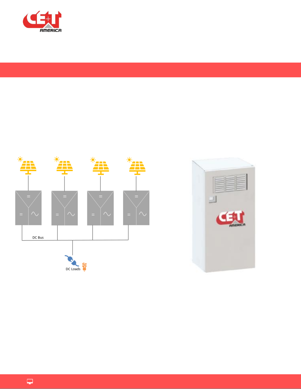
7. Target System
DC bus method is utilized to support DC loads connected on same DC bus. Stabiliti 30C3 power converters
can supporting the DC bus by regulating the DC voltage at a desired setpoint and dynamically sharing the
load equally among multiple stabilitis supporting the same DC bus (this is accomplished by an inbuilt
voltage droop algorithm.) The source of power can come from either AC or the other DC port on Stabiliti.
If nothing is connected to second DC port, then all the power comes from AC port.
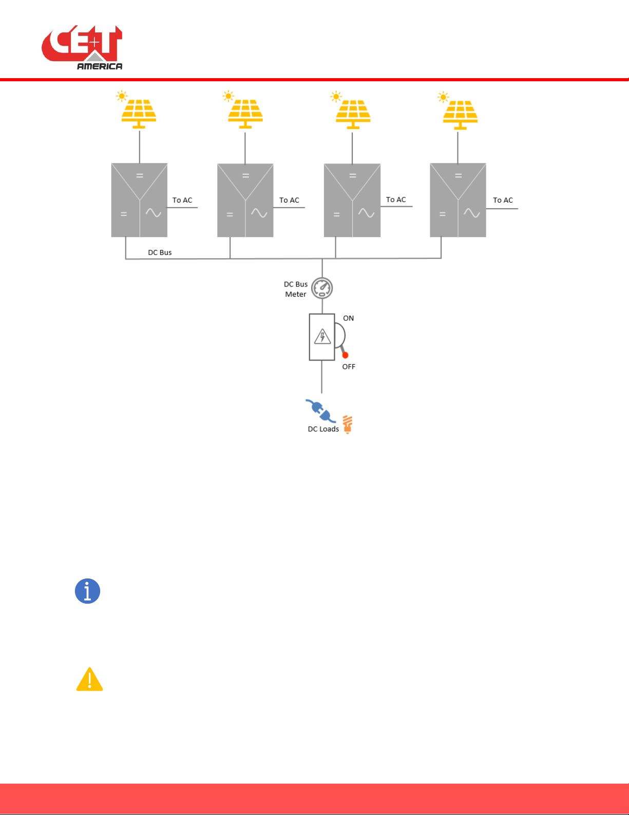
Shown below is a typical application where PV is connected to one of the DC ports (this is optional), the
other DC port is connected to DC loads and AC is connection to 3 phase 480 VAC. Note that batteries may
also be connected instead of PV but batteries will require more management and the use of Site/Central
controller will not be optional in that case.

Figure 1 –DC Bus Method –Typical Setup
Before the system can be used in this way, it must be configured, both physically and software wise, to
support the system.
8. System Configuration –PV + Grid
Before proceeding, please carefully review Stabiliti’s modbus map in detail. Pay close attention to
all scaling factors. It is advisable to work with one stabiliti at a time and with stabiliti link being off
(stabiliti in manual mode with user stop command, i.e. link not running), try all modbus read and
write commands to gain a better understanding of controls and monitoring points.
Warning –Follow local safety codes and guidelines provided by local AHJs for all installations. The
more restrictive/safer guidelines should be always followed.

Figure 2 –DC Bus Method –Supporting via PV + Grid - Configuration Flowchart
Shown above are the steps that must be taken before stabiliti can be used to support DC bus. The flow
chart assumes the system is physically connected as shown in Figure 1 where PV is optional, and AC is
expected to be main source for supporting DC bus.
Once configured right, the system will work autonomously supporting the DC bus using PV and grid, giving
preference to using PV power over AC. In other words, the central or site controller is only required during
initial set up. Initial set up as shown in Figure 2 can also be done using a simple modbus client tool as well.
Even though a central or site controller is not required for normal operation of the system, it is advisable
to have a monitoring system in place to monitor the overall system performance and power flows. Once
configured, the power flows will work as shown in the picture below.
As shown, there are three power flow scenarios, PV = load, PV > Load and PV < Load. As evident, the
power flow will be managed automatically by Stabiliti without requiring any supervision from site/central
controller.
Special Register Settings for MPPT:
To prevent the stabiliti on faulting out when there is no PV output (as PV DC volt will be zero, which is
below default Vmin limit of DC3 port), set register 206 to a value of “-20”. This is mentioned in step 5 of
the flow chart above. Refer to stabiliti modbus map for other settings related to MPPT.

Figure 3 –DC Bus Method –Supporting via PV + Grid –Power Flows
9. System Configuration –Batteries + Grid
Before proceeding, please carefully review Stabiliti’s modbus map in detail. Pay close attention to
all scaling factors. It is advisable to work with one stabiliti at a time and with stabiliti link being off
(stabiliti in manual mode with user stop command, i.e. link not running), try all modbus read and
write commands to gain a better understanding of controls and monitoring points.
Warning –Follow local safety codes and guidelines provided by local AHJs for all installations. The
more restrictive/safer guidelines should be always followed.
As shown below, most of the steps for using batteries will be same except step 5 and addition of step 15
as highlighted in green in the flow chart below.
Warning –Ensure the charging and discharging of batteries is never performed beyond batteries’
safe limits. Stabiliti’s do not communicate with BMS and hence they do not know if its safe to
charge or discharge and what the safe level is. It is the responsibility of Site/Central controller to
ensure safe operation of batteries.

Figure 4 –DC Bus Method –Supporting via Batteries + Grid - Configuration Flowchart
As shown here the power flows are different here as compared to PV. With PV, the stabiliti’s will
automatically route all PV power to DC loads. With batteries, it is the job of central/site controller to
command stabilitis to draw power from batteries to support DC loads. The reason is, Stabilitis do not know
if its ok to discharge and the level of safe discharge. A site/central control can communicate with battery
BMS and determine when its ok to charge/discharge and also the safe level to do so.
Figure 5 - DC Bus Method –Supporting via Batteries + Grid –Power Flows

End of Document
Table of contents