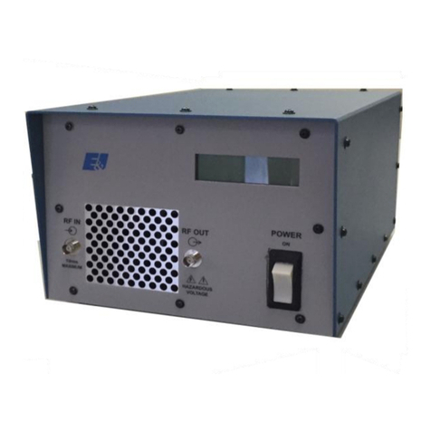
Cerasonar CS-2000DSP4 User manual

Network DSP Power Amplifier
User Manual
cerasonar.de

Index
Chapter 1: Introduction ..................................................................................................... - 1 -
Chapter 2: Technical parameter .........................................................................................- 1 -
2.1 Features .......................................................................................................................- 1 -
2.2 Technical data ..............................................................................................................- 1 -
Chapter 3: Functional Structure .........................................................................................- 3 -
3.1 Description of display .................................................................................................. - 4 -
Chapter 4: Operation of control software - Cerasonar ...................................................... - 5 -
4.1 Operating condition .....................................................................................................- 5 -
4.2 Connections setting .....................................................................................................- 6 -
4.3 DSP functions setting ...................................................................................................- 9 -
4.3.1 DSP functions setting - INPUT .................................................................................- 10 -
4.3.2 DSP functions setting - NOISE GATE .......................................................................- 11 -
4.3.3 DSP functions setting - PEQ-X (input and output) ...................................................- 11 -
4.3.4 DSP functions setting - DELAY (input and output) ..................................................- 13 -
4.3.5 DSP functions setting - MATRIX MIX ...................................................................... - 13 -
4.3.6 DSP functions setting - COMPRESSOR ....................................................................- 14 -
4.3.7 DSP functions setting - LIMITER .............................................................................. - 14 -
4.3.8 DSP functions setting - OUTPUT ............................................................................. - 14 -
4.4 Monitoring and setting of channels ...........................................................................- 15 -
4.4.1 Channel gain level .................................................................................................. - 15 -
4.4.2 Quick buttons of DSP in channels ...........................................................................- 15 -
4.4.3 Group and channels link .........................................................................................- 16 -
4.5 Menu - File ................................................................................................................ - 17 -
4.6 Menu - Device ........................................................................................................... - 17 -
4.7 Menu - Camera (only available in DSP matrix products) ............................................ - 18 -
4.7.1 Camera setting ....................................................................................................... - 18 -
4.7.2 Set Camera Tracking .............................................................................................. - 19 -
4.7.3 Set Mic Tracking .....................................................................................................- 20 -
4.8 Menu - Connection ................................................................................................... - 20 -
4.9 Menu - Preset ............................................................................................................ - 21 -
4.10 Menu - System ........................................................................................................ - 22 -
4.11 FIR filter and function .............................................................................................. - 22 -
4.11.1 FIR filter and applications ......................................................................................- 22 -
4.11.2 Using third party software to adjust FIR magnitude and phase ............................ - 24 -
4.11.3 Using FIR DESIGNER in Cerasonar to adjust FIR magnitude and phase ................. - 29 -
4.11.3.a FIR DESIGNER - Import .......................................................................................- 31 -
4.11.3.b FIR DESIGNER - FIR-EQ .......................................................................................- 31 -
4.11.3.c FIR DESIGNER - Magnitude Correction and Phase Correction ............................ - 32 -
4.11.3.d FIR DESIGNER - Generate ...................................................................................- 33 -
Chapter 5: Connect with 12V trigger .............................................................................. - 34 -

- 1 -
Chapter 1: Introduction
cs-2000dsp4 supports analog input
and output. It can realize a variety of
DSP functions, noise gate, PEQ, delay,
matrix mix, FIR automatic linear phase,
compressor, limiter. The status of its
temperature, gains showed in
colourful IPS display. They can be
quickly debugged and monitored
through the nice GUI software
Cerasonar, which provides a broad
operating space for the construction
and operation of audio amplification
systems.
Applications
Villa house
Performance & Art Center
Broadcast
Stadium
Hotel
Shopping Mall
Retail Store
Restaurant
Chapter 2: Technical parameter
2.1 Features
Analog input and output channels.
Dante 4 input network audio.
Build-in DSP process, noise gate, PEQ, delay, matrix mix, compressor, limiter.
FIR automatic linear phase.
Support mode: stereo, bridge, mono, free matrix.
Support Constant Pressure and Resistance: 100V, 70V, 8Ω, 4Ω.
Colourful IPS display.
Nice GUI control software Cerasonar (PC windows).
USB free driver connecting, support TCP/IP, RS232, RS485, GPIO connections.
Remote on/off amplifier.
Real time remotely monitor status of amplifier.
2.2 Technical data
Model
cs-2000dsp4
INPUT AND OUTPUT CONNECTORS

- 2 -
Input
Balanced 4 x XLR; 4 x Phoenix terminal
Input topology
4 x Phoenix terminal line out
Output
4 x Binding post
Dante
4 channels input
Operating mode
Stereo / Bridge / Parallel /Matrix
Control
TCP/IP, USB, RS485, RS232
POWER
Channels
4
Power@8Ω
4 x 300watts
Power@4Ω
4 x 500watts
Bridge mode@8Ω
2 x 900watts
Constant V. and R.
100V, 70V, 8Ω, 4Ω
DSP PROCESS
Input source
Analog, Dante, Pink noise, White noise, Sine
Input volume
Mute, Phase, Level
Input noise gate
Attack time 1 to 2895ms, Release time 1 to 2895ms,
Threshold level -120dBu to 0dBu
Input PEQ
15 bands PEQ
Input delay
4 x 100ms
DSP matrix
4 x 4
Output PEQ
10 bands PEQ
Output delay
4 x 20ms
Output compressor
Soft-knee, Threshold level, Attack time, Compression
ratio, Releasing time
Output limiter
Voltage 0.01V to 42.43V, Power 0.01w to 450w, Release
time 1 to 2895ms
DSP presets
28 presets for user available
AUDIO PERFORMANCE SPECIFICATIONS
Sampling
48k 24bit
Frequency Response
20Hz to 20kHz (±0.5dB)@1W, 8Ω
Gain
6dB sensitivity: 30dB (x 29.5); 0dB sensitivity: 36dB (x
31.1)
Max input level
6dB sensitivity: 14dBu (3.88V); 0dB sensitivity: 8dBu
(1.94V)
SNR
6dB sensitivity: 97dB; 0dB sensitivity: 97dB
THD+N
<1%@1W to full power
Channel isolation
<-70dB
PROTECTION
Cooling system
Dual fans intelligent control
Remotely control
Power on/standby
Monitor
Temperature, power, voltage, current

- 3 -
Protection
Limiter, high temperature, DC, high frequency, short
circuit, back electromotive force, peak current limiter,
surge current limiter, start delay, power breaker
protection, power supply over-voltage/ under-voltage
protection
ELECTRICAL AND PHYSICAL
Display
320 x 240 pixel, IPS colourful
Power supply
AC100 to 240 50/60Hz
Dimension
Device 483mm*305mm*44.5mm
Package 542mm*453mm*77mm
Weight
Net weight 4kg
Packaged weight 5kg
Chapter 3: Functional Structure
Structure and dimension

- 4 -
3.1 Description of display
Main interface
Main
In IPS display, user can learn status of
this power amplifier, such as device
name, temperature, mute status, gain
level, current preset, volume, operating
mode. When locked, long press 2
seconds to unlock.
Software control
Compress/limiter start
Menu interface
In this menu, user can quickly set
functions including volume, preset,
source, status, rename of device, IP
address, lock automatically, view
information of device and screen.

- 5 -
Volume
Preset
Operating mode
Chapter 4: Operation of control software - Cerasonar
Cerasonar provides user with a fast interaction to control one or more devices
through multiple methods: TCP/IP, USB, common serial port (RS232/485). Easily
set DSP functions of device, GPIO control and inquire central control codes.The
configuration parameter can be stored in presets, convenient for various
applications.
4.1 Operating condition
Cerasonar is suitable for Win7/8/10/11 x86/x64 PC system with Microsoft .NET
Framework 4.0. When connecting device in USB method, the device will

- 6 -
automatically ejects the storage disk, user can unzip software in Windows, no
need to setup.
Double click Cerasonar.exe, the main interface will pop up.
4.2 Connections setting
If connect device by using
network cable, click Setting in
Device List, choose TCP in
Connection windows.

- 7 -
If connect device by using USB
A-B, click Setting in Device List,
choose USB in Connection
windows.
If connect device by using
network cable, click Setting in
Device List, choose COM in
Connection windows. Please
check port and baud rate
carefully for 232 or 485 before
setting.
The software will scan device the method set
in last time, to check if device is connected. If
successfully connected, devices will be shown
in device list.
User can mute device, refresh connecting, or delete device in this window. Single
click device, to load function interface.

- 8 -
When using TCP control, there is a
situation that only one point is
displayed after scanning, but can not
connect device. In this case, user need
to change the IP address of the device
to the same network segment as the
PC computer.
Right-click the device enclosure, a Net
Setting window will show.
Set IP address of device refer to IP
showed in the bottom of the software.
Successfully scanned and connected.

- 9 -
User can link multiple same devices in group by clicking Link button, and then set
group device, group name and main device, link mode and parameter according
to needs.
4.3 DSP functions setting
Double-click HOME icon to open all functional interfaces, or double-click a
function icon separately to open the corresponding interface. When multiple
function windows opened, users can drag the window to switch function
Settings.

- 10 -
4.3.1 DSP functions setting - INPUT
Set source of each channel;
Set sensitivity of each channel
0/6/12dBu;
Set gains, phase or mute in each
channel;
When choosing test signal, user
can select Sine/Pink Noise/White
Noise for each input channel.

- 11 -
4.3.2 DSP functions setting - NOISE GATE
Attack: 1 to 2895ms;
Release: 1 to 2895ms;
Threshold: -120 to 0dBu;
Click to enable
this function.
4.3.3 DSP functions setting - PEQ-X (input and output)
High pass filter
enter value of frequency and select type, press to enable this function:
Butterworth 6/12/18/24/36/48, Bessel 12/24/36/48, Linkwitz-Riley 12/24/36/48.
Low pass filter
enter value of frequency and select type, press to enable this function:
Butterworth 6/12/18/24/36/48, Bessel 12/24/36/48, Linkwitz-Riley 12/24/36/48.
PEQ 15 bands for input channel
Type: PEQ/LSLV/HSLV/ALLPASS-1/ALLPASS-2;

- 12 -
Freq(Hz) Q Gain(dB): input value or use mouse pulley to set value;
Users can also drag the frequency dot on the curve to adjust.
PEQ 10 bands for output channel
Type: PEQ/LSLV/HSLV/ALLPASS-1/ALLPASS-2;
Freq(Hz) Q Gain(dB): input value or use mouse pulley to set value;
Users can also drag the frequency dot on the curve to adjust.
Phase curve: display the phase curve of the current channel.
View: show or hide all balance control points.
Bypass: turn on or off all equalizer EQ of the current channel at the same time
Preset: save all the setting parameter of the equalizer of the current channel to
the computer, and recall the channel equalizer parameter of the computer, which
can be called across channels and devices.
Copy: copy the current channel equalizer parameter value, which can be pasted
to other similar channels (such as input channel parameter can only be copied to
other input channels).
Paste: used in combination with the copy button to paste the last copied
equalizer parameter value to the current channel.
Reset: reset the equalizer parameter to the default parameter values.
As shown in the figure above, the left side is the interface
switching button for each channel. Click to switch the EQ channel, and the color
is the currently selected channel. is the curve color of the EQ channel.
For each channel's EQ curve display switch, check it to enable it to display the
curves of other channels in the current channel interface.

- 13 -
4.3.4 DSP functions setting - DELAY (input and output)
Max 100ms for input channel;
Max 20ms for output channel;
Click to enable this
function;
Click to reset each
channel;
User can switch ft/cm/ms
measurement for delay.
4.3.5 DSP functions setting - MATRIX MIX
In the above figure, input channel (on top side) corresponds to the output
channel. The value box with a value is mixing key of channels. When the mixing
key is green (double-click the value box to switch the state), the input channel
and output channel signal realizes the mixing function.
The right part of the above figure contains the gain, reset button, and clear
button of the matrix mix. Click the value box on the left, and then drag the
sliding block of the matrix mix gain or enter a value in the value box to adjust the
matrix block Click the reset button to reset the matrix mixing function to the
initial one-to-one state; click the clear button to clear all the matrix mixing
functions, and there is no correspondence between the input and output of the
device.

- 14 -
4.3.6 DSP functions setting - COMPRESSOR
Soft knee: 0 to 30;
Threshold: -90 to 21 dB;
Attack: 1 to 2895 ms;
Ratio: 1 to 100;
Release: 1 to 2895 ms;
Click to enable
this function;
Release time should not less
than attack time.
4.3.7 DSP functions setting - LIMITER
Voltage: 0.01 to 42.43V;
Power: 0.01 to 450watts;
Release: 1 to 2895 ms;
Click to enable
this function;
4.3.8 DSP functions setting - OUTPUT
Set phase of signal;
Set mute of output channel;
Set gain of output channel;
M.Vol is used for setting total
volume for device.

- 15 -
4.4 Monitoring and setting of channels
User can monitor gains level of input and output channels.
4.4.1 Channel gain level
There are two kinds of input signal in some
products: ANALOG, DANTE network audio. It will
show a label for user.
Input value, drag gain fader or use mouse pulley to
set value of gain.
4.4.2 Quick buttons of DSP in channels
M Mute
+ Phase
N Noise Gate
E PEQ
D Delay
M Mute
E PEQ
D Delay
C
Compressor
L Limiter
+ Phase

- 16 -
4.4.3 Group and channels link
User can quickly set channels in groups for opening or closing mute, phase, noise
gate, PEQ and delay function.
M Mute
+ Phase
N Noise Gate
E PEQ
D Delay
Channels link for
input
M Mute
E PEQ
D Delay
C Compressor
L Limiter
+ Phase
Channels link for output
When click link button, Channels Link window would show as below:
Select the corresponding channels to link, they will be in group for user to set
parameter.

- 17 -
4.5 Menu - File
New project: the project is restored to the initial open state.
Demo Device: user can view all the functions of the device without affecting the
specific device connected.
Open: open an existing device management project from the computer disk.
Save: save the current equipment management project in the computer disk.
Save as: save the current equipment management project to the computer disk.
4.6 Menu - Device
Devices: view or modify the software version information, device name and
device IP address of the upper and lower computer of the device.
Channel name: set the name of each input and output channel, with memory
function.
Channel copy: copy device input and output channel parameter, can realize
cross-device copy parameter (Note: the same type of device is required).
Central control and GPIO: Cerasonar provides user a quickly way to inquiry
code of Center Control and GPIO setting. More details, please refer to another
user manual <GPIO And Center Control Code User Manual>, it provides whole
guide and codes for user to match every specific system.

- 18 -
4.7 Menu - Camera (only available in DSP matrix products)
4.7.1 Camera setting
Generally, the camera position should be debugged before the tracking starts,
Table of contents
Other Cerasonar Amplifier manuals

