Cerio eXtreme DT-100G User manual

CERIO Corporation
DT-100G
eXtreme High Power Wireless Router
User’s Manual
V1.0

Table of Contents
1. Introduction ............................................................................................................................4
1.1 Overview......................................................................................................................4
1.2 Applications in Wireless Network ...........................................................................4
1.3 Product Benefit ...........................................................................................................7
1.4 Panel Function Description .......................................................................................9
1.5 Hardware Installation Steps .....................................................................................10
1.6 Software Configuration ............................................................................................11
2. Router AP Mode Configuration ............................................................................................22
2.1 External Network Connection..................................................................................23
2.2 Wireless LAN Network Creation ..............................................................................30
2.3 Wireless Network Expansion...................................................................................44
2.4 System Management ................................................................................................46
2.5 Access Control List ..................................................................................................57
2.6 Resource Sharing .....................................................................................................66
2.7 System Status ...........................................................................................................69
3 WISP + AP Mode Configuration ..........................................................................................79
3.1 External Network Connection..................................................................................80
3.2 Access Point Association ........................................................................................87
3.3 Wireless LAN Network Creation ..............................................................................94
3.4 System Management ..............................................................................................104
3.5 Access Control List ................................................................................................115
3.6 Resource Sharing ...................................................................................................124
3.7 System Status .........................................................................................................127
4. Clinet Bridge + Universal Repeater Mode Configuration ...................................................138
4.1 External Network Connection ..............................................................................139
4.2 Configure LAN Setup .............................................................................................140
4.3 Configure Wireless General Setting .....................................................................144
4.4 Wireless Advanced Setup......................................................................................146
4.5 Site Survey..............................................................................................................148
4.6 Wireless LAN Network Creation ............................................................................150
4.7 System Status .........................................................................................................161
5. System Management .........................................................................................................169
5.1 Configure Management..........................................................................................169
5.2 Configure System Time .........................................................................................172
5.3 Configure UPnP......................................................................................................173
5.4 Configure SNMP Setup ..........................................................................................174
6. Uility ...................................................................................................................................176
6.1 Backup / Restore and Reset to Factory................................................................176
6.2 Firmware Upgrade..................................................................................................177
6.3 Network Utility ........................................................................................................178
6.4 Reboot .....................................................................................................................179
7. System Status....................................................................................................................180

7.1 System Overview ....................................................................................................180
7.2 Clients ( Associated Clients Status ).....................................................................185
7.3 Show WDS Status...................................................................................................187
7.4 Extra Information....................................................................................................188
7.5 QoS Plot ..................................................................................................................190
7.6 Event Log ................................................................................................................191
Appendix A. Windows TCP/IP Settings ................................................................................192
Appendix B. WEB GUI Valid Characters ............................................................................194
Appendix C. System Manager Privileges .............................................................................198
Appendix D. Enabling UPnP in Windows XP .......................................................................200
Product Specification.............................................................................................................203

User’s Manual
eXtreme High Power Wireless Router
4
1 Introduction
1.1 Overview
The CERIO DiToG Wireless Router is an easy-to-install and cost-effective solution for
most of Home / Office wireless deployments, Including 500mW wireless out-power to
extend the range and increase the performance of our wireless network. And provide
hardware quickly button for simplify control the Wireless Radio ON/ Off, You can by
your environment Chick to button to on or off wireless Radio . The network
administrator can centrally manage the DT-100G via a Web browser. , This eXtreme
Power Access Point must be your best choice.supports most up-to-date security
encryption including WPA/WPA2-PSK,WPA/WPA2- Enterprise , IEE802.1x , Moreover,
support MAC & IP Access control list (ACL) . Wireless Router is embedded with a
IEEE 802.11b/g access point that allows you to build up a wireless LAN,Wireless
connection from CERIO DT-100G 500mW High Power broadband router an WISP’s
wireless signal . CERIO DiToG DT-100G repeats the signal from a Wireless Internet
Service Provider(WISP) to your home or office, The WISP+AP mode access Internet
connection of both wired and wireless stations to the Internet. This Wireless
Broadband Router must be your best choice.
1.2 Applications in Wireless Network
DiToG DT-100G is a multiple mode system which can be configured either as a
wireless gateway or an access point as desired. It also can be used WDS link for
Ethernet network expansion. This section depicts different applications on Router AP
Mode, AP Mode, WDS Mode, WISP Mode, Client Bridge + Universal Repeater
Mode and WISP + AP Mode.

User’s Manual
eXtreme High Power Wireless Router
5
1.2.1 Configuration on Router AP Mode (Gateway + Access Point + WDS)
1.2.1.1 Example 1 : Router AP without WDS
It can be deployed as a gateway with wireless Access Point
1.2.1.2 Example 2 : Router AP with WDS
It can be deployed as a gateway with wireless Access Point and provides WDS link for
network extension.
1.2.2 Configuration on WISP AP Mode (Router Client + Access Point)
It can be used as an Wireless Internet Service Provider (WISP) to receive
wireless signal over the last mile, helping WISPs deliver wireless broadband

User’s Manual
eXtreme High Power Wireless Router
6
Internet service to new residential and business customers. In this mode, the
DiToG DT-100G is a gateway with NAT and DHCP Server functions. The wireless
and wired clients of DiToG DT-100G are on the different subnet from Main Base
Station and it accepts wireless connections from client devices.
1.2.3 Configuration in Client Bridge + Universal Repeater Mode
It can be used as an Client Bridge + Universal Repeater to receive wireless signal
over last mile applications, helping WISPs deliver wireless broadband Internet
service to new residential and business customers. In this mode, DiToG DT-100G
is enabled with DHCP Server functions. The wired clients of DiToG DT-100G are
in the same subnet from Main Base Station and it accepts wireless connections
from client devices.

User’s Manual
eXtreme High Power Wireless Router
7
1.3 Product Benefit
Key Feature
¾Operation Modes : Router + A P Mode , WISP + AP Mode,Universal Repeater
Mode.
¾Maxmum Security with 802.1x, WPA, WPA2(TKIP/AES)
¾Support Hardware Quickly Wireless Radio ON/ Off Button .
¾WiFi connection as WAN , in WISP + AP mode , the device run as DHCP server to
assign IP address to clients out of a private IP address pool behind a NAT
¾Universal Repeater : It extends the range of your wireless network while
simultaneously Allowing wired and wireless clients to access
Router Feature
¾DHCP Client、PPPoE Client、Static IP setting function.
¾Support DHCP Server and Provide Virtual Server. And UPnP functions
¾PPPOE/PPTP/L2TP functions
¾Support VPN Pass Throughput ( PPTP , IPSec , L2TP )
¾MAC Cloning
¾IEEE802.3 Bridging
¾Masquerading (NAT)
¾Proxy DNS ,Dynamic DNS ,NTP Client
¾Virtual DMZ, Virtual Server (IP / Port Forwarding)
¾Support IP / MAC Filter
¾Bandwidth trafic Shaping
Wireless Access Point Feature
¾In Router + AP Mode ,WDS support to extend wireless coverage by connecting
wirelessly to another , WDS capable wireless device to 8 WDS links
¾Beacon interval: adjustable to best adapt to the deployment environment
¾IAPP : to facilitate faster roaming for the stations among different APs nearby
¾Support Adjustable transmission power : 9 Levels
¾Wireless Bandwidth Control by Upload and Download setting 256~8192kbps to
control
Authentication/Encryption (Wireless Security)

User’s Manual
eXtreme High Power Wireless Router
8
¾WEP 64/128/152bits EAP-TLS + Dynamic WEP , EAP-TTLS + Dynamic WEP
PEAP/MSPEAP + Dynamic WEP
¾WPA-PSK/TKIP,WPA-802.1x/TKIP, 802.11i WPA2-PSK/CCMP/AES, WPA2
(802.1x /CCMP / AES
¾Setting for TKIP/CCMP/AES key’s refreshing period
¾Hidden SSID broadcast support
¾Access Control list (ACL) by MAC Address
Quality of Service
¾Download and Upload traffic control
¾Packet classifications via DSCP (Differentiated Services Code Point)
¾Control Policy by IP/IP Ranges/ MAC/ Layer-7 Application Service
¾Layer-7 Protocol Support
¾Traffic Analysis and Statistics
¾No. of Max. Policy setting : 10
¾DiffServ/TOS
¾IEEE 802.11p/COS
¾IEEE802.11e WMM
¾QoS Bandwidth Control by Upload and Download setting 8~8192kbps to
control
Parental Control
¾Blocking Control Policy by IP Range / MAC Group / Port / Layer-7 Protocol
¾URL Blocking
Management
¾Web-Based management interface
¾Remote configuration and management
¾Remote firmware upgradeable
¾Software one-button-click to reset back to factory defaults
¾Utilities for system configuration backup and restoration
¾UPnP (Universal Plug and Play)
¾NTP Time Synchronization
¾Administrative Access : HTTP and HTTPS
¾Support SNMP v2c/v3
¾DHCP client

User’s Manual
eXtreme High Power Wireless Router
9
¾UPNP support
¾Support Event log
¾Support CLI access via Telnet and SSH
1.4 Panel Function Description
There is several LED indicators and button on the front of the DiToG DT-100G. Please
refer to the definitions below :
Front Panel Up Panel
1. Wireless Radio On/Off Button: To push the “button” to enable and disable the
Wireless Radio functions.
2. Reset Button: Press and hold the Reset button for more than 10~20 seconds to
reset the system to default configurations.
3. LAN Ethernet port and LAN LED: This port is a Private LAN port that
authentication is not required for clients to access network via this port. and LAN
LED: Link/Act on Port . Green LED ON indicates connection, OFF indicates no
connection, and FLASH.
4. WAN LED : Green LED ON indicates connection, OFF indicates no connection,
and FLASH
5. WLAN: Green LED FLASH indicates Wireless ON, and FLASH quickly indicates
Wireless Transmit quickly.
6. Power: Green LED ON indicates power on, and OFF indicates power off.
7. DC Injector ( 12V ): Attach the power socket here

User’s Manual
eXtreme High Power Wireless Router
10
8. WAN Ethernet port: This port is for connection to external network switch.
1.5 Hardware Installation Procedures
The procedures to install the “DT-100G eXtreme High Power Wireless Router” please refer
to below .
1. Connecting your computer to the LAN port
Attach one end of the Ethernet cable with RJ-45 connector to your hub, switch or a
computer’s Ethernet port, and the other end to one of the LAN ports of your
“DT-100G eXtreme High Power Wireless Router”.
2. Connecting Cable/ADSL Modem to the WAN port
Connect the Ethernet cable attaching to your Cable/ADSL modem to the WAN port
of your “DT-100G eXtreme High Power Wireless Router”.
3. Connecting the power adapter
Connect the single DC output connector of the power adapter to the power jack on
the side of the “DT-100G eXtreme High Power Wireless Router”. Then plug the
Power Adapter into an AC outlet.
4. Power on the following devices in this order:
Cable/ADSL modem, Router, and PCs.

User’s Manual
eXtreme High Power Wireless Router
11
1.6 Software Configuration
DiToG DT-100G supports web-based configuration. Upon the completion of hardware
installation, DiToG DT-100G can be configured through a PC/NB by using its web
browser such as Internet Explorer 6.0 or later.
Default IP Address: 192.168.1.254
Default Subnet Mask: 255.255.255.0
Default Username and Password
Mode Router AP
Management Account Root Account Admin Account
Username root admin
Password default admin
Mode WISP Mode (by default DHCP server is enabled)
Management Account Root Account Admin Account
Username root admin
Password default admin
Mode Client Bridge + Universal Repeater Mode
Management Account Root Account Admin Account
Username root admin
Password default admin
Configure your PC/NB to connect with DT-100G
Please make sure your network interface card configuration has been completed and
activated on your operating system and connected to one of the LAN port of DT-100G
through Cat.5 or Cat.5e cable. Please make sure the LED on DT-100G is already on
and the LED corresponds with the port which you connected.
By default, the DT-100G will enable DHCP service automatically and distribute an IP
address to your host. the DT-100G default IP is "192.168.1.254". make sure your PCs
are configured to obtain an IP address automatically from the Router by the steps below.
User’s Manual
eXtreme High Power Wireless Router
12
zWindows 2000/XP
Please follow the steps below to setup your computer
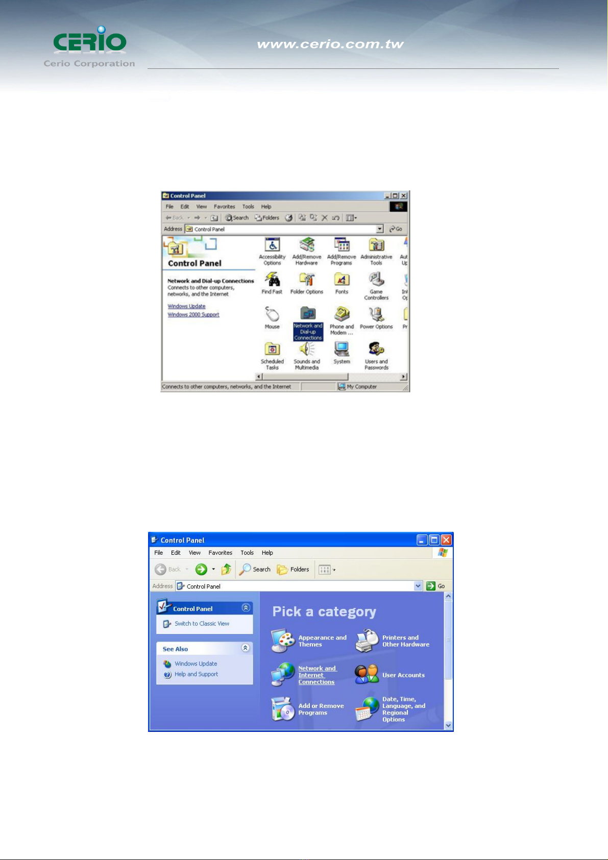
5. Go to Start ÆSettings ÆControl Panel
6. Double click the icon Network and Dial-up Connections
7. If you are Windows XP user, please do so.
Go to Start ÆSettings ÆControl Panel
8. Click Network and Internet Connections

User’s Manual
eXtreme High Power Wireless Router
13
9. Click Network Connections ,Highlight the icon Local Area Connection, right click
your mouse, and click Properties
10. Highlight Internet Protocol (TCP/IP), and then press Properties button

User’s Manual
eXtreme High Power Wireless Router
14
11. Choose Obtain an IP address automatically and Obtain DNS server address
automatically, and then press OK to close the Internet Protocol (TCP/IP) Properties
window
12. Press OK to close the Local Area Connection Properties window

User’s Manual
eXtreme High Power Wireless Router
15
zWindows Vista / Widows 7
Please follow the steps below to setup your computer:
1. Go to Start ÆSettings Æ Control Panel
2. Click Network and Sharing Center
3. Click Manage Network Connections
4. Highlight the icon Local Area Connection, right click your mouse, and click
Properties

User’s Manual
eXtreme High Power Wireless Router
16
5. Highlight Internet Protocol Version 4 (TCP/IP) and then press Properties button
6. Choose Obtain an IP address automatically and Obtain DNS server address
automatically, and then press OK to close the Internet Protocol (TCP/IP)
Properties window

User’s Manual
eXtreme High Power Wireless Router
17
7. Press OK to close the Local Area Connection Properties window
If you finish the operating system TCP/IP setting you can follow the instructions are as
follows to check your IP address:
zWindows98/98se
1. Click Run... on this menu.
2. In the text box that appears type "winipcfg". The "IP address" field shows the IP
address for the default network adapter.
3. If you can't find your adapter IP address, please use the drop-down menu near
the top of the window to browse IP address information for alternate network
adapters.
zWindows 2000/XP/Vista
1. Please make sure that you do have the authority to login as "administrator"
privilege.
2. Click "Start Æ Program ÆAccessories ÆCommand Prompt" or "Start Æ
Run...", and then type in "cmd.exe" and press "ENTER" button.
3. It will prompt a "Windows Command-Line" window.
4. Type "ipconfig" after the command of "C:>" and then press "ENTER" button.
5. The "Windows Command-Line" will show you the "Network Interface Card"
information in the window, please take notice of the value of "IP Address" and

User’s Manual
eXtreme High Power Wireless Router
18
"Default Gateway".
6. The value of "Default Gateway" is the IP address of DT-100G.
zLinux / Unix-Like
1. At first please make sure that your NIC are already enable and works property.
2. And be sure you have “root” privilege or you already are one of the member of
“network” group is depending on your Linux distribution or Unix-like type.
3. Please login to your Linux console and make sure your Linux support “DHCP
client” function then after “#” type “ifconfig” or “ifconfig -a” then press “ENTER”
button.
4. It will appear your present network interface card IP address in the console,
please take notice of the value of “IP address” and “Gateway”.
The value of “Gateway” is the IP address of DT-100G
Checking PC’s IP and Connection with the Router
After configuring the TCP/IP protocol, use the ping command to verify if the computer
can communicate with the Router. To execute the ping command, open the DOS
window and ping the IP address of the “DT-100G eXtreme High Power Wireless
Router” at the DOS prompt:
zFor Windows 98/Me: Start -> Run. Type command and click OK.
zFor Windows 2000/XP: Start -> Run. Type cmd and click OK.
At the DOS prompt, type the following command:
If the Command window returns something similar to the following:

User’s Manual
eXtreme High Power Wireless Router
19
C:\Documents and Settings\admin>ping 192.168.1.254
Pinging 192.168.1.254 with 32 bytes of data:
Reply from 192.168.1.254: bytes=32 time=1ms TTL=64
Reply from 192.168.1.254: bytes=32 time=1ms TTL=64
Reply from 192.168.1.254: bytes=32 time=1ms TTL=64
Reply from 192.168.1.254: bytes=32 time=1ms TTL=64
Ping statistics for 192.168.1.254:
Packets: Sent = 4, Received = 4, Lost = 0 (0%
loss),
Approximate round trip times in milli-seconds:
Minimum = 1ms, Maximum = 1ms, Average = 1ms
Then the connection between the router and your computer has been successfully established.
If the computer fails to connect to the router, the Command window will return the following:
C:\Documents and Settings\admin>ping 192.168.1.254
Pinging 192.168.1.254 with 32 bytes of data:
Request timed out.
Request timed out.
Request timed out.
Request timed out.
Ping statistics for 192.168.1.254:
Packets: Sent = 4, Received = 0, Lost = 4 (100% loss)
Verify your computer's network settings are correct and check the cable connection
between the router and the computer. In order to make the whole network operate
successfully, it is necessary to configure the DT-100G through your computer has a WEB
browser installed. Please follow up the steps listed below.
Login to DT-100G
Now, we will going to setup DT-100G through your WEB browser that installed on your
PC/NB, please do as follow:

User’s Manual
eXtreme High Power Wireless Router
20
1. Startup Internet Explorer and enter http://192.168.1.254, then press Enter
2. You will enter the user name and password. The default user name is “root” ,
password is “default”, too. You can’t modify you user name but can modify your
password. You need modify you password when you successfully login, incase
anyone else may invade your Internet illegally.
3. After successful login, in the home page of the DT-100G, the left navigation bar
shows the main options to configure the system. In the right navigation screen is the
summary of system status for viewing the configurations.
Table of contents
Other Cerio Wireless Router manuals


Popular Wireless Router manuals by other brands


EnGenius
EnGenius ENS202EXT-CP Quick installation guide

Franklin Wireless
Franklin Wireless RG1000 user manual

Huawei
Huawei AI Cube quick start

NETGEAR
NETGEAR WNDAP350 - ProSafe 802.11n Dual Band Wireless Access... Product data

Encore
Encore ENHWI-N2 Specifications

TRENDnet
TRENDnet TEW-611BRP Quick installation guide


