Aircat 6410 User manual

7.2.2.3 GENERAL SAFETY RULES
• Multiple hazards. Read and understand the safety instructions before
installing, operating, repairing, maintaining, changing accessories on, or
working near the power tool. Failure to do so can result in serious bodily
injury.
• Onlyqualiedandtrainedoperatorsshouldinstall,adjustorusethepower
tool.
• Donotmodifythispowertool.Modicationsmayreducetheeffectiveness
of safety measures and increase the risks to the operator.
• Donotdiscardthesafetyinstructions–givethemtotheoperator.
• Do not use a tool if the tool has been damaged.
• Warningsshallbegivenagainsttheriskofexplosionorreduetothe
material being processed;
• Warningsshallbegivenagainsttheriskofcutting.
7.2.2.4 PROJECTILE HAZARDS
• Failureoftheworkpiece,ofaccessories,orevenofthetoolitselfmay
generatehighvelocityprojectiles.
• Always wear impact-resistant eye protection during operation of the tool.
The grade of protection required should be assessed for each use.
7.2.2.5 ENTANGLEMENT HAZARDS
• Entanglement hazard - choking, scalping and/or lacerations can occur if
neckware,hairorglovesarenotkeptawayfromtoolandaccessories.
7.2.2.6 OPERATING HAZARDS
• Useofthetoolmayexposetheoperator’shandstohazardsincluding
crushing,impacts,cutsandabrasionsandheat.Wearsuitableglovesto
protect hands.
• Operators and maintenance personnel must be physically able to handle
the bulk, weight and power of the tool.
• Holdthetoolcorrectly:bereadytocounteractnormalorsuddenmove-
ments–havebothhandsavailable.
• Maintain a balanced body position and secure footing.
• Keep hands away from rotating or reciprocation accessories, spindles or
othermovingparts.
• Releasethestartandstopdeviceinthecaseofaninterruptionofthe
energy supply
• Use only lubricants recommended by the manufacturer.
7.2.2.7 REPETITIVE MOTIONS HAZARDS
• Whenusingapowertool,youmayexperiencediscomfortinyourhands,
arms, shoulders, neck, or other parts of your body.
• While using a power tool, position your body in a comfortable posture.
Maintainsecurefootingandavoidawkwardoroff-balancedpostures.
Changingyourpostureduringextendedtasksmayhelpavoiddiscomfort
and fatigue.
• Ifyouexperiencesymptomssuchaspersistentorrecurringdiscomfort,
pain, throbbing, aching, tingling, numbness, burning sensation, or stiff-
ness, do not ignore these warning signs. Promptly tell your employer and
consultaqualiedhealthprofessional.
7.2.2.8 ACCESSORY HAZARDS
• Only use sizes and types of accessories and consumables that are recom-
mended by the power tool manufacturer.
7.2.2.9 WORKPLACE HAZARDS
• Slips, trips and falls are major causes of workplace injury. Be aware of
slippery surfaces caused by use of the tool and also of trip hazards caused
by the air line or hydraulic hose.
• Proceedwithcareinunfamiliarsurroundings.Hiddenhazardsmayexist,
such as electricity or other utility lines.
• Thispowertoolisnotintendedforuseinpotentiallyexplosiveatmo-
spheres and is not insulated from coming into contact with electric power.
• Make sure there are no electrical cables, gas pipes etc. that could cause a
hazard if damaged by use of the tool.
7.2.2.10 DUST AND FUME HAZARDS
• Dust from some work processes can cause cancer, birth defects or other
respiratory diseases. Risk assessment of these hazards and implementa-
tion of appropriate controls is essential.
• Ifthepneumatictoolisusedinadustlledenvironmentexhaustaircan
cause a dust hazard
• Dusts and fumes generated when using power tools can cause ill health
(forexample:cancer,birthdefects,asthmaand/ordermatitis);riskas-
sessment of these hazards and implementation of appropriate controls of
is essential.
• Risk assessment should include dust created by the use of the tool and
thepotentialfordisturbingexistingdust.
• Operate and maintain the power tool as recommended in these instruc-
tions, to minimize dust or fume emissions
• Directtheexhaustsoastominimizeddisturbanceofdustinadustlled
environment
• Where dusts or fumes are created, the priority shall be to control them at
the point of emission.
• Allintegralfeaturesoraccessoriesforthecollection,extractionor
suppression of airborne dust or fumes should be correctly used and
maintainedinaccordancewiththemanufacturer’sinstructions.
• Select, maintain and replace the consumable/inserted tool as recom-
mendedintheseinstructions,topreventanunnecessaryincreaseindust
or fumes
• Use respiratory protection as instructed by your employer or as required
by occupational health and safety regulations;
7.2.2.11 NOISE HAZARDS
• Unprotectedexposuretohighnoiselevelscancausepermanent,
disabling, hearing loss and other problems such as tinnitus (ringing,
buzzing,whistlingorhummingintheears);
• Risk assessment of these hazards and implementation of appropriate
controls of is essential.
• Appropriate controls to reduce the risk may include actions such as
dampingmaterialstopreventworkpiecesfrom‘ringing’
• Use hearing protection as instructed by your employer or as required by
occupational health and safety regulations;
• Operate and maintain the power tool as recommended in these instruc-
tions,topreventanunnecessaryincreaseinnoiselevels;
• Select, maintain and replace the consumable/inserted tool as recom-
mendedintheseinstructions,topreventanunnecessaryincreasein
noise.
7.2.2.12 VIBRATION HAZARDS
• Exposuretovibrationcancausedisablingdamagetothenervesand
blood supply of the hands and arms;
• Wear warm clothing when working in cold conditions and keep your
hands warm and dry;
• Ifyouexperiencenumbness,tingling,painorwhiteningoftheskinin
yourngersorhands,stopusingthepowertool,andtellyouremployer.
Youshouldalsoseekmedicaladvicefromaqualiedoccupationalhealth
professional.
• Operate and maintain the power tool as recommended in these instruc-
tions,topreventanunnecessaryincreaseinvibration;
• Select, maintain and replace the consumable/inserted tool as recom-
mendedintheseinstructions,topreventanunnecessaryincreasein
vibrationlevels;
• Support the weight of the tool in a stand, tensioner or balancer, because
the operator can then use a lighter grip to support the tool.
• Hold the tool with a light but safe grip taking account of the required
handreactionforces,becausetheriskfromvibrationisgenerallygreater
when the grip force is higher.
7.2.3 ADDITIONAL SAFETY INSTRUCTIONS FOR PNEUMATIC POWER
TOOLS - AIR SUPPLY & CONNECTION HAZARDS
• Airunderpressurecancausesevereinjury.
• Always shut off air supply, drain hose of air pressure and disconnect tool
from air supply when not in use, before changing accessories or when
making repairs.
• Neverdirectairatyourselforanyoneelse.
• Whippinghosescancausesevereinjury.Alwayscheckfordamagedor
loosehosesandttings.
• Wheneveruniversaltwistcouplings(clawcouplings)areused,lockpins
must be installed.
• Donotexceedthemaximumairpressurestatedonthetool.
• Use whip check safety cables to safeguard against possible hose to tool
and hose to hose connection failure.
• Nevercarryanairtoolbythehose.
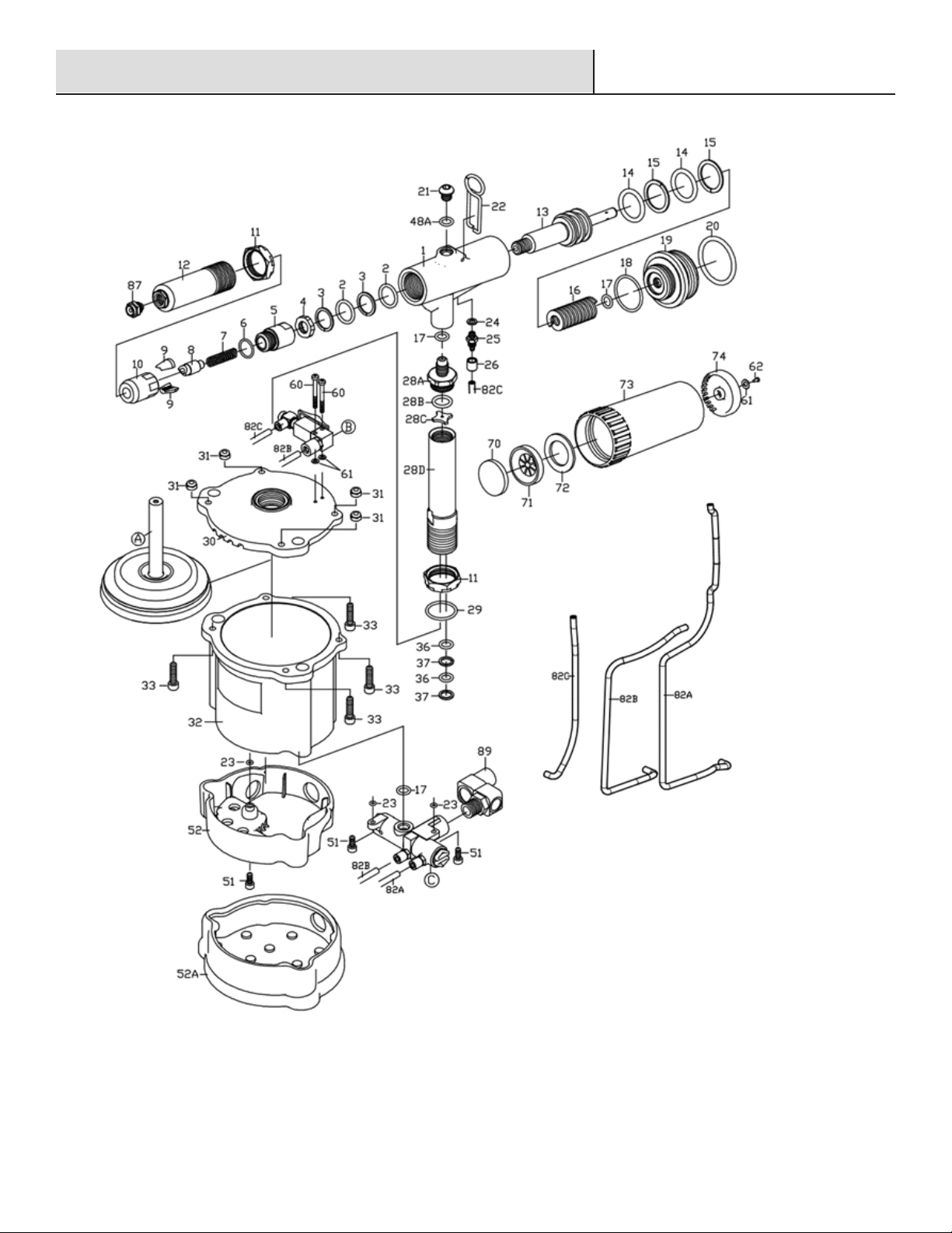
MODEL# 6410 3/16-IN. AIR HYDRAULIC RIVETER
MODEL# 6420 1/4-IN. AIR HYDRAULIC RIVETER
Operation Manual & Parts List

Safety Information (continued)
AIR COMPRESSOR AND AIR TOOL SAFETY
1. Risk of Bursting. Do not adjust the regulator to result in output
pressure greater than the marked maximum pressure of this air
tool.
2. Ensure the hose is free of obstructions or snags. Entangled or
snarled hoses can cause loss of balance or footing and may
become damaged.
3. Never leave a tool unattended with the air hose attached.
4. Do not operate this tool if it does not contain a legible warning
label.
5. Do not continue to use a tool or hose that leaks air or does not
function properly.
6. Never direct a jet of compressed air toward people or animals.
7. Protect your lungs. Wear a face or dust mask if the operation is
dusty.
Specifications: 6410
Specifications: 6420
1. This tool is NOT designed for use in explosive atmospheres.
2. Always wear eye protection when using or when near a tool that is in use.
3. Inspect the tool for damage before connecting to the air supply.
4. Trained personnel must perform tool repair and maintenance at the prescribed intervals.
5. Disconnect the air supply when adjusting or servicing the tool.
6. Keep fingers off the trigger when connecting the air supply or if the air supply fails.
7. Keep fingers away from the front of the tool when connecting the air supply or setting rivets.
8. Keep hair, fingers, and loose clothing away from moving parts of the tool.
9. DO NOT point the tool at anyone.
10. DO NOT operate the tool with the HEAD removed or without the Deflector or Mandrel Collector.
11. DO NOT look directly at the tool from the front or the back during use or when connected to air supply.
12. DO NOT modify the tool in any way. The modification will void any applicable warranties and could damage the tool or physi-
cally injure the user.
13. The operating air pressure must not exceed 110 psi (7.5 bar).
WARNING: This product can expose you to lead, which is
known to the State of California to cause cancer. For more
information, go to www.P65Warnings.ca.gov.
Model
No. Description
Traction
Power
(lbs)
Stroke
Length
(in)
Net Weight
(lbs)
Operating
Air
Pressure
(PSI)
Air Inlet
Size
(in-NPT)
Min. Hose
Size
(in)
Nosepieces
Equipped
(in)
Max
Capacity
6410
3/16” Air-
Hydraulic
Riveter
2000 7/8 4.2 90 1/4 3/8 5/32, 3/16,
Monobolt 3/16
Max.3/16
Structural
rivets in all
materials
Model
No. Description
Traction
Power
(lbs)
Stroke
Length
(in)
Net Weight
(lbs)
Operating
Air
Pressure
(PSI)
Air Inlet
Size
(in-NPT)
Min. Hose
Size
(in)
Nosepieces
Equipped
(in)
Max
Capacity
6420
1/4” Air-
Hydraulic
Riveter
3700 63/64 5.6 90 1/4 3/8
3/16, 1/4,
Monobolt 3/16,
1/4
Max. 1/4
Structural
rivets in all
materials

Recommended Air Line Set-Up
Part Description
AAir Tool
B Quick Plug
C Quick Coupler
D Air Hose
E In-line Regulator
F In-line Lubricator
G In-line Filter
H Air Compressor
WARNING: This product can expose you to lead, which is
known to the State of California to cause cancer. For more
information, go to www.P65Warnings.ca.gov.
Operation
1 Operation Setup
□Ensure the correct nosepiece is fitted and the lock nut is
tightened.
□Ensure the mandrel collector is fitted securely.
□Connect the tool to the air supply
This rivet gun is designed to operate on 90 PSIG. Lower
pressure (below 90 PSIG) will reduce performance of
the tool. Higher air pressure (over 90 PSIG) raises the
performance of the tool beyond its rated capacity and
could cause serious damage to the tool and the user.
2 Installing the blind rivets
WARNING: Disconnect the tool from the air supply before
servicing or changing accessories.
□Turn on the suction switch so the broken mandrel can be
drawn into the collector.
□Insert the mandrel of blind rivet into the nosepiece.
□Insert the head of the blind rivet ino the workpiece.
□Depress the trigger.
3 Storing the rivet gun
WARNING: Disconnect the tool from the air supply before
servicing or changing accessories.
□Slide the suction switch to the left (OFF) position.
□Disconnect the rivet gun to the air supply.
□Follow maintenance guidelines before storing tool.

Ensure the air line is shut-off and drained of air before removing this tool for service. This will prevent the tool from operating if the throttle
or trigger is accidentally engaged.
LUBRICATION
□An in-line filter-regulator-lubricator is recommended as it increases tool life and keeps the tool in sustained operation.
□Regularly check and fill the in-line lubricator with air tool oil. Avoid using excessive amounts of oil.
□Adjust the in-line lubricator by placing a sheet of paper next to the tool’s exhaust ports and holding the throttle open approximately 30
seconds. The lubricator is properly set when a light stain of oil collects on the paper.
□If it is necessary to store the tool for an extended period of time (overnight, weekend, etc.), generously lubricate the tool through the air
inlet. Run the tool for approximately 30 seconds to ensure the oil is evenly distributed throughout the tool. Store the tool in a clean and
dry environment.
□Recommended lubricants: Air tool oil or any other high grade turbine oil containing moisture absorbent, rust inhibitors, metal wetting
agents, and an EP (extreme pressure) additive.
Maintenance
1. Cleaning the front end of hydraulic section
a. Disconnect the air supply.
B. Loosen the lock nut on the head.
C. Remove the head.
D. Loosen the jaw housing nut, jaw housing and jaw
housing coupler.
E. Clean all parts.
F. Replace the parts.
2. Priming hydraulic oil.
A. Remove lock nut, plug screw and o-ring.
B. Screw in the priming pump with the proper amount of
hydraulic oil.
C. Remove the priming pump.
D. Replace the plug screw and o-ring.
E. If over-primed, remove the plug screw and o-ring to allow
hydraulic fluid to spill from the hydraulic chamber. Replace the plug
screw and o-ring.

3. How to replace the o-ring and back-up ring.
a. Take off the plastic grip (right and left).
Maintenance
b. Take off PU pipe in the air switch, collector switch, and pressure
sensor.
c. Remove 4 screws on the air cylinder body. Take off upper
cover. Clear the air cylinder and air piston.
d. Remove hydraulic section and hydraulic tube.
e. Remove hydraulic plunger assembly and clean.
f. Remove and clean hydraulic tube and piston.
g. Replace o-rings and back-up-rings on the tools.
h. After all the parts are cleaned, reassemble the tool.
i. Follow step 2 above to re-prime hydraulic oil into the tool.

REF.NO. PART NUMBER DESCRIPTION QTY REF.NO. PART NUMBER DESCRIPTION QTY
1 9922101R HYDRAULIC SECTION (RED) 1 *48 9OR0711 O-RING 1
*2 9OR1621 O-RING (2) 2 *49 9OR1014 O-RING (2) 2
*3 9BR1621 BACK-UP RING (2) 2 50 9107409 INLET PLUG (2) 2
4 9214306 NUT 1 50A 9922409 SCOKET SCREW 1
5 9214305 JAW HOUSING COUPLER 1 51 9HC00407010 SET SCREW (3) 3
6 9OR1417 O-RING 1 52 9922402 BASE 1
7 9214308 SPRING 1 52A 9922404 RUBBER BOOT 1
8 9214302 JAW PUSHER 1 53 9922701 VACUUM VALVE 1
*9. 9612303 JAW (2) 2 54 9922702 SLEEVE 1
10 9612324A JAW HOSING 1 55 9OR0811 O-RING (2) 2
11 9918106 LOCK NUT (2) 2 56 9PW0510 WASHER 1
12 9612105 HEAD 1 57 9612712 SWIVEL 1
13 9922301 HYDRAULIC PLUNGER 1 58 9612713 SOCKET 1
*14 9OR2229 O-RING (2) 2 59 9922703 VACUUM SWITCH 1
*15 9BR2229 BACK-UP RING (2) 2 60 9HC00305020 SET SCREW (2) 2
16 9922309 RETURN SPRING 1 61 9PW0306 WASHER (7) 7
17 9OR0812 O-RING (4) 4 62 9ST0310 SCREW (5) 5
18 9OR2832 O-RING 1 63 9107602 VALVE BODY 1
19 9922102 REAR GLAND 1 64 9107601 BLEEDING VALVE 1
20 9OR3542 O-RING 1 65 9107201R TRIGGER 1
21 9HR00812508 SET SCREW 1 66 9922107RV PLASTIC GRIP-RIGHT 1
22 9258801 HANGER 1 67 9922107C BATTERY CAP 1
23 9OR0306 O-RING (8) 8 68 9922107LV PLASTIC GRIP-LEFT 1
24 9612714 WASHER (6) 6 70 9919904 SILENCER 1
25 9612717 SOCKET (5) 5 71 9919903 MUFFLER SEAT 1
26 9612711 CAP (6) 6 72 9919905 SILENCER 1
28A. 99221082 HYDRAULIC TUBE CONNECTOR-B 1 73 9919901 MANDREL COLLECTOR 1
28B 9OR1417 O-RING 1 74 9919906 MUFFLER CAP 1
28C 98211012 HYDRAULIC TUBE WASHER 1 75 9612901 DEFLECTOR 1
28D 99221081 HYDRAULIC TUBE CONNECTOR-A 1 76 9612902 PU TUBE (OPT.) 1
29 9OR2025 O-RING 1 77 9612904 MULTI-WRENCH (A) 1
30 9922401R UPPER COVER (RED) 1 78 9918905 MULTI-WRENCH (B) 1
31 9NN005080B NUT (4) 4 79 9314755 5MM HEX. WRENCH 1
32 9922403R AIR CYLINDER BODY (RED) 1 80 9922901 OILER 1
33 9HC00508020 SET SCREW (4) 4 81 9144905 17X19 WRENCH (2) 2
*36 9OR1419 O-RING (2) 2 82A 9922704A 2.5X4 PU HOSE 1
*37 9BR1419 BACK-UP RING (2) 2 82B 9922704B 2.5X4 PU HOSE 1
40 9922501 PLUNGER ROD 1 82C 9922704C 2.5X4 PU HOSE 1
41 9202505 BUMPER RING 1 87 9612705 NOSE PIECE 5/32”(4.0MM) 1
42 9107503 FRONT HEAD DISC 1 9612706 NOSE PIECE 3/16”(4.8MM) 1
43 9819502 PACKING RING 1 9612746 MONOBOLT NOSEPIECE
3/16"(4.8MM)
1
44 9107502 LOWER PLATE 1 89 992L2 AIR INLET ASSEMBLY 1
45 9919211 VALVE CASE 1 * 90 6410-PK *SERVICE KIT (OPT.) 1
*46 9OR0408 O-RING (2) 2 (NO.02.03.09.14.15.36.37.46.48.49)
47 9919202A VALVE STEM 1
Service Parts / Exploded View Drawing MODEL 6410
3/16-IN. RIVET GUN

Service Parts / Exploded View Drawing MODEL 6410
3/16-IN. RIVET GUN

REF.NO. PART NUMBER DESCRIPTION QTY REF.NO. PART NUMBER DESCRIPTION QTY
1 9725101R HYDRAULIC SECTION 1 48* 9OR0711 O-RING 1
2* 9OR1823 O-RING (2) 2 49* 9OR1014 O-RING (3) 3
3* 9BR1823 BACK-UP RING (2) 2 50 9107409 INLET PLUG (2) 2
4 9214306 NUT 1 50A 9922409 SOCKET SCREW 1
5 9819305 JAW HOUSING COUPLER 1 51 9HC00407010 SET SCREW (3) 3
6 9OR1417 O-RING 1 52 9202402 BASE 1
7 9819308 SPRING 1 52A 9202404 RUBBER BOOT 1
8 9214302 JAW PUSHER 1 53 9922701 VACUUM VALVE 1
9* 9819303 JAW (2) 2 54 9922702 SLEEVE 1
10 9819324 JAW HOSING 1 55 9OR0811 O-RING (2) 2
11 9819106 LOCK NUT 1 56 9PW0510 WASHER 1
12 9819105 HEAD(FOR BLIND RIVET) 1 57 9612712 SWIVEL 1
13 9725301 HYDRAULIC PLUNGER 1 58 9612713 SOCKET 1
14* 9OR2835 O-RING (2) 2 59 9922703 VACUUM SWITCH 1
15* 9BR2835 BACK-UP RING (2) 2 60 9HC00305020 SET SCREW (2) 2
16 9202309 RETURN SPRING 1 61 9PW0306 WASHER (7) 7
17 9OR0812 O-RING (3) 3 62 9ST0310 SCREW 1
18 9OR3034 O-RING 1 62A 9HC00305006 SET SCREW (4) 4
19 9725102 REAR GLAND 1 63 9107602 VALVE BODY 1
20 9OR3542 O-RING 1 64 9107601 BLEEDING VALVE 1
21 9HR00812508 SET SCREW 1 65 9107201R TRIGGER 1
22 9258801 HANGER 1 66 9202107RV PLASTIC GRIP-RIGHT 1
23 9OR0306 O-RING (9) 9 67 9202107C BATTERY CAP 1
24 9612714 WASHER (6) 6 68 9202107LV PLASTIC GRIP-LEFT 1
25 9612717 SOCKET (5) 5 68A 9HR002504506 SET SCREW (2) 2
26 9612711 CAP (6) 6 70 9919904 SILENCER 1
27 9520106 NUT 1 71 9919903 MUFFLER SEAT 1
28A 95201082 HYDRAULIC TUBE CONNECTOR-B 1 72 9919905 SILENCER 1
28B 9OR1417 O-RING 1 73 9919901 MANDREL COLLECTOR 1
28C 98211012 HYDRAULIC TUBE WASHER 1 74 9919906 MUFFLER CAP 1
28D 92021081 HYDRAULIC TUBE CONNECTOR-A 1 75 9612901 DEFLECTOR 1
28E 95201083 WASHER 1 76 9612902 PU TUBE (OPT.) 1
29 9OR2025 O-RING 1 77 9612904 MULTI-WRENCH (A) 1
30 9202401R UPPER COVER (RED) 1 78 9918905 MULTI-WRENCH (B) 1
31 9NN005080B NUT (4) 4 79 9314755 5MM HEX. WRENCH 1
32 9202403R AIR CYLINDER BODY (RED) 1 80 9922901 OILER 1
33 9HC00508020 SET SCREW (4) 4 81A 9144905 17X19 WRENCH (2) 2
36* 9OR1621 O-RING (2) 2 81B 9144906 19X21 WRENCH 1
37* 9BR1621 BACK-UP RING (2) 2 82A 9202704A 2.5X4 PU HOSE 1
40 9202501 PLUNGER ROD 1 82B 9202704B 2.5X4 PU HOSE 1
41 9202505 BUMPER RING 1 82C 9202704C 2.5X4 PU HOSE 1
42A 9202504 FRONT HEAD DISC A 1 87 9612706 NOSE PIECE 3/16"(4.8MM) 1
42B 9202503 FRONT HEAD DISC B 1 9612708 NOSE PIECE 1/4"(6.4MM) 1
43 9920505 PACKING RING 1 9612746 MONOBOLT NOSEPIECE 3/16"(4.8MM) 1
44 9202502 LOWER PLATE 1 9612748 MONOBOLT NOSEPIECE 1/4"(6.4MM) 1
45 9919211 VALVE CASE 1 89 992L2 AIR INLET ASSEMBLY 1
46* 9OR0408 O-RING (2) 2 * 90 6420-PK * SERVICE KIT (OPT.) 1
47 9919202A VALVE STEM 1 (NO.02.03.09.14.15.36.37.46.48.49)
Service Parts / Exploded View Drawing MODEL 6420
1/4-IN. RIVET GUN

Service Parts / Exploded View Drawing MODEL 6420
1/4-IN. RIVET GUN

Ref.
No.
Part Number Description Qty Ref.
No.
Part Number Description Qty
91 6410-AK Plunger Kit
40, 41, 42A, 42B, 43 & 44
1 93 6410-CK Inlet Valve Kit
23, 24, 25, 26, 45, 46, 47, 48,
49, 50, 50A
1
92 6410-BK Vacuum Valve Kit
23, 24, 25, 26, 53, 54, 55, 56, 57,
58, 59
1 94 919901-K Mandrel Collector Assembly
61, 62, 70, 71, 72, 73, 74
1
Service Parts / Exploded View Drawing KIT PARTS
919901-K Mandrel Collector Assembly
6410-BK Vacuum Valve Kit
6410-CK Inlet Valve Kit
6410-AK Plunger Kit
MODEL 6410
3/16-IN. RIVET GUN

Service Parts / Exploded View Drawing
Ref.No. Part Number Description Qty Ref.No. Part Number Description Qty
91 6420-AK Plunger Kit 1 93 6420-CK Inlet Valve Kit 1
40, 41, 42A, 42B, 43 & 44 23, 24, 25, 26, 45, 46, 47,
48, 49, 50, 50A
92 6420-BK Vacuum Valve Kit 1 94 919901-K Mandrel Collector Assembly 1
23, 24, 25, 26, 53, 54, 55, 56,
57, 58, 59
61, 62, 70, 71, 72, 73, 74
MODEL 6420
1/4-IN. RIVET GUN
6420-BK Vacuum Valve Kit
6420-CK Inlet Valve Kit
6420-PK Plunger Kit
919901-K Mandrel Collector Assembly
KIT PARTS

Warranty
Florida Pneumatic Manufacturing Company (“Florida Pneumatic”) warrants that its AIRCAT and NITROCAT air tools will be free from defects in material and
workmanship for a period of two years from the date of original purchase, except for our AIRCAT VIBROTHERM DRIVE air tools that are warrantied to be free
from defects in material and workmanship for 3 years from the original date of purchase (the “Warranty Period”).
Because Florida Pneumatic cannot control the quality of tools sold by unauthorized sellers, this warranty applies only to tools that were purchased from
Florida Pneumatic or a Florida Pneumatic authorized seller in the United States, unless otherwise prohibited by law. Florida Pneumatic reserves the right to
reject warranty claims from purchasers for tools purchased from unauthorized sellers, including unauthorized internet sites. This warranty does not cover
any defects due to normal wear and tear, damage due to misuse, alteration to the product, negligence, or damage due to repair by anyone other than Florida
Pneumatic or its authorized service centers. This warranty applies to the tool only. This warranty does not apply to any attached accessories/consumable
products, such as drill chucks, sander backing pads, air hammer retainers and chisels, “kit” accessories, or any other accessory included with the tool. This
warranty is also limited to the original, end-user purchaser.
If you wish to make a warranty claim based upon a product defect, please return the tool at issue to Florida Pneumatic or a Florida Pneumatic Authorized
Service Center freight prepaid and include your name, address, phone number, a copy of your receipt or other proof of purchase showing the original date of
purchase, and a description of the suspected defect. A list of Florida Pneumatic Authorized Service Centers can be found at https://www.florida-pneumatic.
com/media/uploads/Service-Centers.pdf.
Florida Pneumatic will repair or replace, in its discretion, a defective product or product part(s) covered by this warranty. You must submit your warranty
claim within the applicable Warranty Period.
It is Florida Pneumatic’s policy to continue to improve our products, and Florida Pneumatic reserves the right to make changes in design or construction of
its products at any time without incurring any obligation with respect to products previously sold.
There are no warranties which extend beyond those stated herein. Any implied warranties that may be applicable to the tools, including implied warranties
of merchantability or fitness for a particular purpose, are limited in duration to the duration of this warranty. Some States do not allow limitations on how
long an implied warranty lasts, so the above limitation may not apply to you. Under no circumstances shall Florida Pneumatic be liable for any special,
incidental, or consequential damages based upon breach of this warranty, breach of contract or strict liability. Some States do not allow the exclusion or
limitation of incidental or consequential damages, so the above limitation or exclusion may not apply to you. This warranty gives you specific legal rights,
and you may also have other rights which vary from State to State.
If you have any questions about whether a seller is authorized, call us at (800) 356-3392 or email authorizedseller@florida-pneumatic.com.
Troubleshooting
Symtom Possible Cause Solution
Rivet cannot be set by a single
pull
1. Low working air pressure
2. Tool requires re-priming
3. Worn Jaws or dirt in Jaws
4. Broken Jaws
5. Rivets required longer stroke
1. Check air pressure at the tool.
2. Adjust the front head correctly according to the
instruction
3. Replace the Jaws
The tool can’t do suction 1. The Suction Switch didn’t open Turn on the Suction Switch. Vacuum hoses in the
housing are bended.
Jaws will not grip rivet mandrel 1. Worn Jaws or build up of dirt on Jaws
2. Jaw Housing loose
3. Weakened Jaw Pusher Spring
1. Clean before replace new Jaws
2. Tighten Jaw Housing, Jaw Housing Coupler and
Nut
3. Replace new Jaw Pusher Spring
Broken rivet mandrel can’t be
released by Jaws
1. Dirty Jaws and Jaw Housing
2. Weakened Jaw Pusher Spring
3. Hydraulic oil over primed.
1. Clean and re-lubricate
2. Replace Jaw Pusher Spring
3. Remove Plug Screw and O-Ring, let it spill till
stop by itself
Broken rivet mandrel jammed
inside the Head
1. Damaged Jaws
2. Damaged or dirty Jaw Pusher
1. Replace Jaws
2. Replace or clean Jaw Pusher
This manual suits for next models
1
Table of contents
Other Aircat Tools manuals