Certified Tracking Solutions TITAN GPS CRX User manual

QUICK INSTALL GUIDECRX RECORDER
CALL TO TESTTHE DEVICE BEFORE CLOSING UP
DASH. FAILURE TO FOLLOW INSTRUCTIONS MAY
DAMAGE EQUIPMENT AND VOID WARRANTY
CERTIFIED
TRACKING
SOLUTIONS
1.780.391.3800
TOLL FREE 1.855.287.4477 (CTS4GPS)
STEP 1 MOUNT CRX RECORDER BOX
Find a location for the recorder box. Example: Under Drivers Seat.
Ensure recorder box is securely affixed to the vehicle in a level horizontal position with lock facing
the REAR of the vehicle. Use the provided mounting brackets.
Ensure client will have access to unlock enclosure
PACKAGE CONTENTS
POWER CABLE
A/V OUTPUT CABLE
CRX RECORDER
DC
8 ~ 40V
EVENT BUTTON
CAMERA INPUT CABLE
MOUNTING BRACKET/COVER
LTE ANTENNA
GPS ANTENNA
WIRE CLIPS + VELCRO
Getting Started
Park the vehicle on a flat surface and ensure the engine is off.
CAMERA EXTENSION CABLE(S)
CELLULAR MODEM BACKUP POWER MODULE

QUICK INSTALL GUIDECRX RECORDER
STEP 2 CONNECT AND MOUNT CELLULAR MODEM
Connect the blue 4-pin molex connector to the USB2 BLUE connection point on the back of the
recorder box
Ensure modem is securely fastened
Ensure modem is not near any sources of interference
STEP 3 MOUNT GPS AND CELLULAR ANTENNAS
Failure to adhere to these suggestions will result in a weak GPS and/or Cellular signal and will affect
the performance of the device.
Secure in upper portion of dash in a hidden location with top of antenna facing skyward.
Example: Above instrument cluster.
Do not cover with metal or position near any source of interference (Vehicle Radio, BCM). Keep a
safe distance of at least 24”.
Do NOT attach the LTE antenna to a metal surface.
Provide a minimum distance of 5 inches of separation between the GPS and Cellular antenna.
STEP 4 CONNECT AND MOUNT EVENT BUTTON
We recommend consulting with the client as to their preferred mounting location
Prepare/clean the surface
Affix the event button onto the dash within easy reach of the driver
a) Connect Red Wire to “Sensor In” #5 on CRX wiring Harness
b) Connect Black Wire to Ground (BAT-) #5 wire on Digital IO / AV Harness
STEP 5 MOUNT CAMERA(S) (THE CRX CAN ACCOMMODATE UP TO EIGHT CAMERAS)
Windshield mounting:
a) Preparation
Ensure glass surface is clean and dry (important!)
Glass temperature should not be too hot or cold (between 50F (10C) and 80F (27C).
b) Mounting
Adjust the bracket by rotating it to the desired angle
Attach the provided 3M adhesive pad to the bracket and press firmly [Ensure glass is clean and
dry BEFORE attaching]
Secure to windshield behind the rear view mirror as high on the windshield as possible but still
within the windshield wiper zone. FMCSA mandates the camera portion of the device should
reside within the top 2 inches of the vehicle wiper sweep. [Hold firm pressure for 30 seconds].

QUICK INSTALL GUIDECRX RECORDER
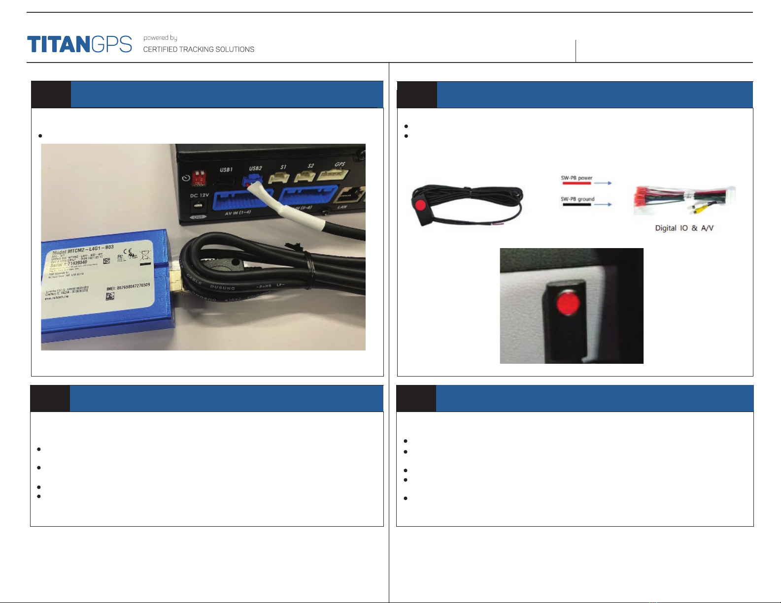
STEP 6 CONNECT IGNITION
In order to function properly the device needs to be connected to a suitable “True” Ignition source
This source has battery voltage whenever the vehicle is turned on and zero volts whenever the
vehicle is turned off.
This source does NOT drop in voltage during crank.
Connect the White wire of the Power Cable harness to this ignition source.
Wiring Connections
Confirm with the client as to which optional connections are required. Required connections
include Power, Ground and Ignition. Optional connections are listed below.
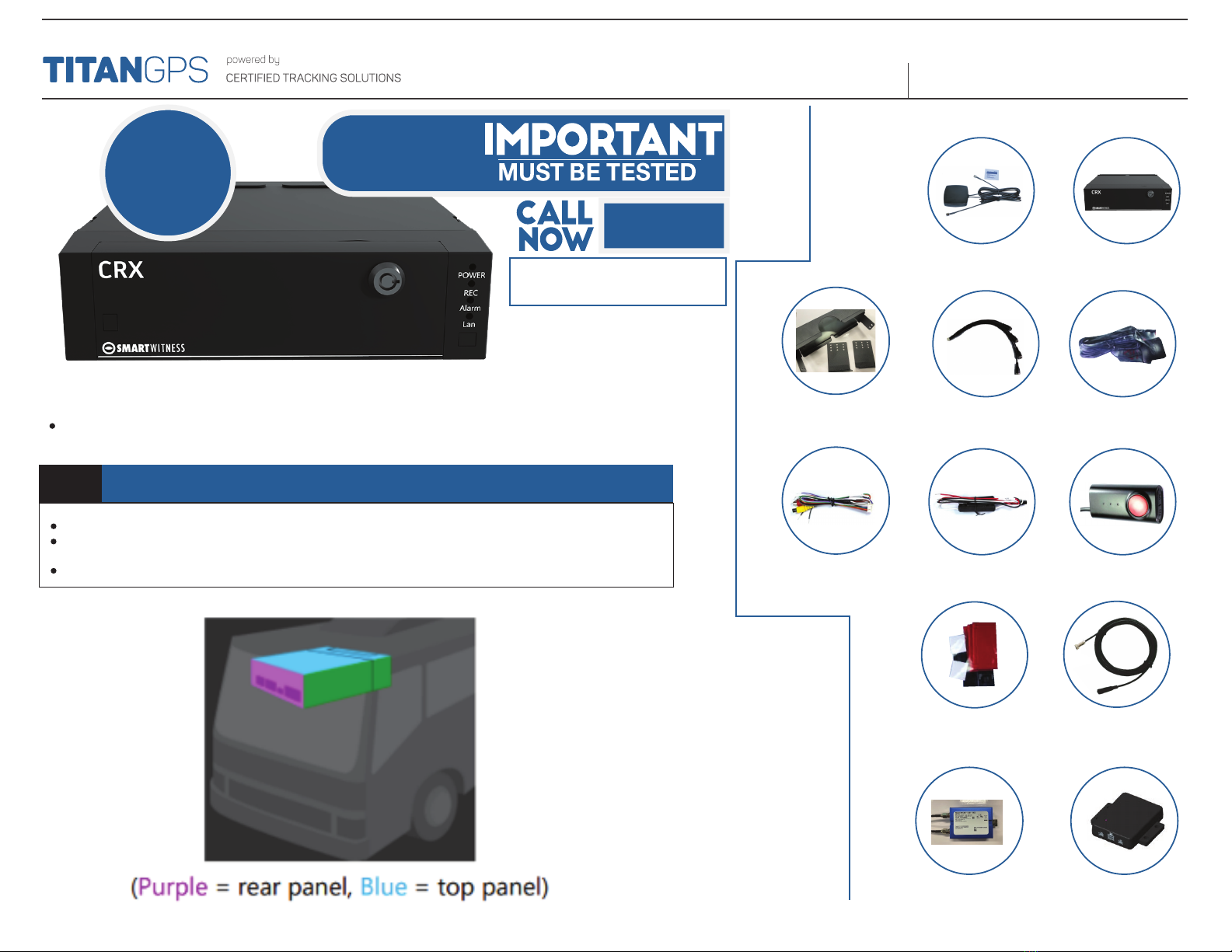
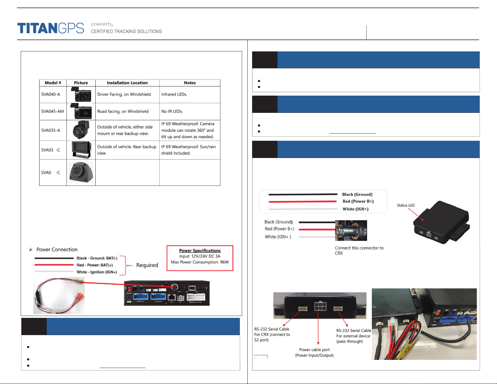
The CRX has various camera models offered which should be installed in an appropriate location.
Here is a reference guide for the common models.
7
25 Exterior Side-Mount camera.
Great for side mirror applications.
IP69K rated for weatherproof
applications.
Recommended Mounting Locations STEP 7 CONNECT CONSTANT POWER
The device requires a minimum 12V constant [Battery Power] on this line to function. [Max 24v].
Do not remove/bypass the fuse
Connect the Red wire of the Power Cable harness to this constant source.
STEP 8 CONNECT GROUND
For best results, create a new connection to bare-metal chassis ground
Do not use a shared ground or supplied ground from any module or device
Connect the Black wire of the Power Cable harness to this ground.
STEP 9 CONNECT BATTERY BACKUP MODULE
The battery backup module will provide the CRX with a safe way to shut down should the power be
interrupted. Proper installation of this module requires the connection of three cables;
a) Complete the Power, Ground and Ignition connections to the battery backup module using the
suggestions above.
b) Connect DC OUT cable to DC IN port of the CRX recorder box
c) Connect the included serial cable to the DVR port and the S2 port of the CRX recorder box
Ch1: Road Facing Camera Ch3: Left Side Mount Camera
Ch2: Driver Facing Camera Ch4: Right Side Mount Camera
Ch5-8: Various
Recommended Camera Connections

QUICK INSTALL GUIDECRX RECORDER
Recommended Camera Connections:
STEP 10 CONNECT OTHER WIRING (AUDIO/VIDEO CABLE) – OPTIONAL
If directed by the client, connect other optional wires as necessary.
STEP 11 ROUTE AND CONNECT CAMERA(S)
The CRX recorder box can accommodate up to 8 cameras. Two Camera Extension Cables are
included that connect to the CRX recorder box.
a) Connect each camera to a Camera Extension Cable
b) Connect the Camera Extension Cables to the CRX recorder box
Ch1: Road Facing Camera
Ch2: Driver Facing Camera
Ch3: Left Side Mount Camera
Ch4: Right Side Mount Camera
Ch5-8: Various
STEP 12 ROUTE AND CONNECT HARNESSES
a) Route and connect GPS Antenna to “GPS” Input on CRX recorder box
b) Route and connect Cellular Antenna to the 2 matching connectors on the Cellular Modem
c) Connect Audio/Video Cable to “Digital IO / AV OUT” connector on the CRX recorder box
d) Route and connect the circular three pin Power connector to the “DC IN” on the CRX recorder box
STEP 13 OPTIONAL – MOUNT AND CONNECT LCD MONITOR WITH VIDEO OUTPUT CABLE
Before continuing:
Consult the installation guide included with the LCD monitor
Consult with the client as to where they would like the LCD monitor to be mounted.
a) Securely mount the LCD monitor in a position where it will not affect the driveability of the vehicle
b) Connect the RCA from the LCD monitor to the Audio/Video Input cable
c) Connect the LCD power cable to IGNITION and GROUND. DO NOT connect to constant power.

QUICK INSTALL GUIDECRX RECORDER
STEP 15 COMPLETE MOUNTING COVER
Using the provided Phillips screws, slide the end Cover Plate over the connected wiring for the CRX
Recorder Box
Ensure that the wires are not being pinched or pulled.
STEP 14 CALL TO TEST
STEP 16 ADMINISTRATIVE DETAILS
Give provided locking keys and any extra parts/accessories to the fleet owner/administrator.
1.780.391.3800
TOLL FREE 1.855.287.4477 (CTS4GPS)
powered by: Certified Tracking Solutions
QUESTIONS?
To TEST the device, call us NOW!
1.855 2874477
Table of contents
Popular Measuring Instrument manuals by other brands

Seametrics
Seametrics S Series instructions

PCB Piezotronics
PCB Piezotronics P356A70 Installation and operating manual

Brooks Instrument
Brooks Instrument Sho-Rate Series Installation & operation manual

Adash
Adash VA5 Pro user manual

Endress+Hauser
Endress+Hauser nivotester FTL 325 P Functional safety manual

Logitek
Logitek ULTRA-VU NBC896 Operation & service manual