CERTUSS 500 - 1800 EC User manual
DE/GB
DE/GB
Operating Instructions
Betriebsanleitung
500 – 1800 TC
The power of steam

2
Seite
Inhaltsverzeichnis 2 – 3
Übersicht
unktionsschemen 4
Gasfeuerung und Rauchgasrückführung 4a – 6
Ölfeuerung und Rauchgasrückführung 6a – 8
Kombiausführung Gas-/Ölfeuerung 8a – 10
1 Allgemeines 11
1.1 Piktogramme 11
1.2 Bestimmungsgemäße Verwendung 11
1.3 Allgemeine Vorschriften 12
2 Sicherheit 13
2.1 Anforderungen an Personen 13
2.2 Pflichten des Betreibers 13
2.3 In der Bundesrepublik Deutschland 13
2.4 Einteilung nach DGRL 13
2.5 Verantwortliche Personen bestimmen
und einweisen 14
2.6 Elektrische/elektronische Einrichtungen 14
2.7 Sicherheit bei Wartungsarbeiten 15
2.8 Ersatzteile 15
2.9 Entsorgung von Schmier- und
Problem stoffen 15
2.10 Mögliche elektrische Netzversorgung 16
3 Funktion 17
3.1 unktionsbeschreibung Dampfautomat 17
3.2 Beschreibung der Gasfeuerung 19
3.3 Beschreibung Gasfeuerung mit
Rauchgasrückführung 21
3.4 Beschreibung der Ölfeuerung 22
3.5 Beschreibung Ölfeuerung mit
Rauchgasrückführung 24
3.6 Beschreibung der Kombifeuerung 25
3.7 Betrieb mit Thermotimat 28
3.8 Betrieb ohne manuellen Eingriff
bis 24h 31
3.9 Betrieb ohne manuellen Eingriff
bis 72h 32
4 Touchscreen 33
4.1 Symbolerklärungen 33
4.2 Sprachen 34
5 Erstmalige Inbetriebnahme 35
5.1 Installation 35
5.2 Inbetriebnahme 36
6 Starten und Abschalten 38
6.1 Manuelles Starten/Abschalten 38
6.2 Thermotimat aktivieren/programmieren 43
6.3 Brennstoffwechsel bei Kombiausführung 47
7 Meldungen 50
7.1 Warnmeldungen 50
7.2 Einstellungen programmieren 55
7.3 Störabschaltungen und deren Anzeigen 57
Technische Änderungen vorbehalten. Technical specifications are subject to change.
Inhaltsverzeichnis Table of Contents
Page
Table of Contents 2 – 3
Survey
unctional diagrams 4
Gas firing and flue gas return 4a – 6
Oil firing and flue gas return 6a – 8
Combined version gas/oil firing 8a – 10
1 General notes 11
1.1 Pictograms 11
1.2 Appropriate use 11
1.3 General prescriptions 12
2 Safety 13
2.1 Staff requirements 13
2.2 Obligations of the operator 13
2.3 In the ederal Republic of Germany 13
2.4 Classification according to DGRL 13
2.5 Determine and instruct persons
in charge 14
2.6 Electrical/electronical devices 14
2.7 Safety during maintenance works 15
2.8 Spare parts 15
2.9 Disposal of lubricants and problematic
substances 15
2.10 Selection of electrical power supply 16
3 Function 17
3.1 Description steam generator 17
3.2 Description of the gas firing 19
3.3 Description gas firing with flue gas return 21
3.4 Description of the oil firing 22
3.5 Description oil firing with flue gas return 24
3.6 Description of combined firing 25
3.7 Operation with Thermotimat 28
3.8 Operation without manual intervention
up to 24 hours 31
3.9 Operation without manual intervention
up to 72 hours 32
4 Touchscreen 33
4.1 Symbol explanations 33
4.2 Languages 34
5 First commissioning 35
5.1 Installation 35
5.2 irst starting 36
6 Starting and stopping 38
6.1 Manual starting/switching off 38
6.2 Activating/programming Thermotimat 43
6.3 uel change at the combined version 47
7 Indications CERTOMAT 50
7.1 unction indications 50
7.2 Programming settings 55
7.3 ault shut-downs and their displays 57

3
Seite
8 Prüfung Dampfanlage 58
8.1 Betriebsbedingungen Speisewasser 58
8.2 Prüfanweisungen für die Dampfanlage 58
8.3 Wassermangelsicherung prüfen 59
8.4 Sicherheitsventil oder Dampfdruckbegrenzer
prüfen 61
8.5 Luftdruckwächter prüfen 62
8.6 lammüberwachung prüfen 63
9 Wartung Dampfanlage 64
9.1 Wartungsanweisungen 64
9.2 Entwässerung bei rostgefahr 65
9.3 Konservierung bei längerem Stillstand 67
9.4 Kesselsteinansatz entfernen 69
9.5 Einstellbeispiele Dampfdruckregelung 72
9.6 Heizsystem wechseln 73
9.7 Heizsystem entrußen 75
9.8 Messanleitung Brennereinstellung 77
10 Wasserpumpe 80
10.1 Wasserpumpe 500 - 1000 TC / 10 - 32 bar 80
10.2 Wasserpumpe 1300 TC / 10 - 32 bar
1500 - 1800 TC / 10 - 16 bar 82
10.3 Wasserpumpe 1500 - 1800 TC / 25 - 32 bar 84
11 Prüfung und Wartung Wasserpumpe 86
11.1 Hinweise 86
11.2 Wartung 86
11.3 Instandsetzung 87
12 Technische Daten 88
13 Anschlüsse 89
13.1 Gas-Anschluss 90
13.2 Öl-Anschluss 91
13.3 Rauchgas-Anschluss 92
14 Physikalische Werte 93
14.1 Umrechnungstabelle Wasserhärte 92
14.2 Abgasmenge 93
14.3 Anforderung an Kesselspeisewasser 93
15 Feuerungsautomat 94
15.1 Zulassungen 94
15.2 Besondere Merkmale 94
15.3 unktions- und Störanzeigen 94
15.4 lammenstromanzeige 94
Technische Änderungen vorbehalten. Technical specifications are subject to change.
Inhaltsverzeichnis Table of Contents
Page
8 Control steam plant 58
8.1 Operation conditions for feed water 58
8.2 Testing instructions for steam plant 58
8.3 Check water shortage safety device 59
8.4 Checking the safety valve or the steam
pressure limiter 61
8.5 Checking the air pressure detector 62
8.6 Checking the flame monitoring 63
9 Maintenance steam plant 64
9.1 Maintenance instructions 64
9.2 Draining in danger of frost 65
9.3 Preservation in case of longer standstill 67
9.4 Remove scale deposits 69
9.5 Setting examples for steam pressure controlling 72
9.6 Change heating system 73
9.7 Desoot heating system 75
9.8 Measuring instruction burner adjustment 77
10 Water pump 80
10.1 Water pump 500 - 1000 TC / 10 - 32 bar 80
10.2 Water pump 1300 TC / 10 - 32 bar
1500 - 1800 TC / 10 - 16 bar 82
10.3 Water pump 1500 - 1800 TC / 25 - 32 bar 84
11 Control and maintenance water pump 86
11.1 Notices 86
11.2 Maintenance 86
11.3 Repairing 87
12 Tecnical data 88
13 Connections 89
13.1 Gas connection 90
13.2 Oil connection 91
13.3 lue gas connection 92
14 Physical values 93
14.1 Water hardness calculation table 92
14.2 Exhaust gas quantity 93
14.3 Requirements for steam generator
feed water 93
15 Firing control automat 94
15.1 iring control automat approvals 94
15.2 Special features 94
15.3 unction and malfunction indications 94
15.4 lame signal indication 94
GB
DE

4
Funktionsschemen
Functional diagrams
Funktionsschema
Functional diagram
Ölfeuerung
Oil firing
Gasfeuerung
Gas firing
Kombifeuerung Erdgas/Öl
Combined firing natural gas/oil
Gasfeuerung mit Rauchgasrückführung
Gas firing with flue gas return
66 42
79
41
44
98
97
46
92
91
93
79
46
43
64
80
66 65
42
59
79
41
44
98
46
42
79
41
44 98
46
92 91
93
97
64
43
43
40b
40a
79
80
40b
40a
79
80
40b
40a
106
21 11 15 17
20
3108
86
16
87
57
9
19
88
13
61
54
75
77
56
10
87
8
18
107
87
78
4
72
14
36
49
57
51
46
50
7
9
Y
Y
65
59
39
102
67
4a
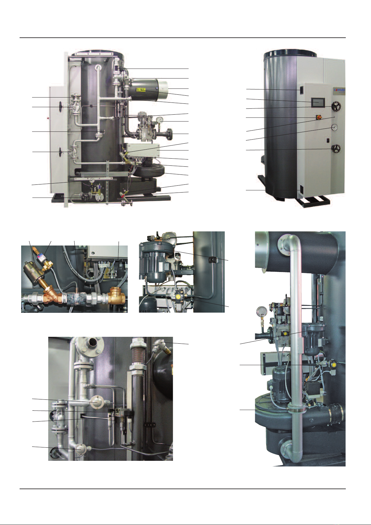
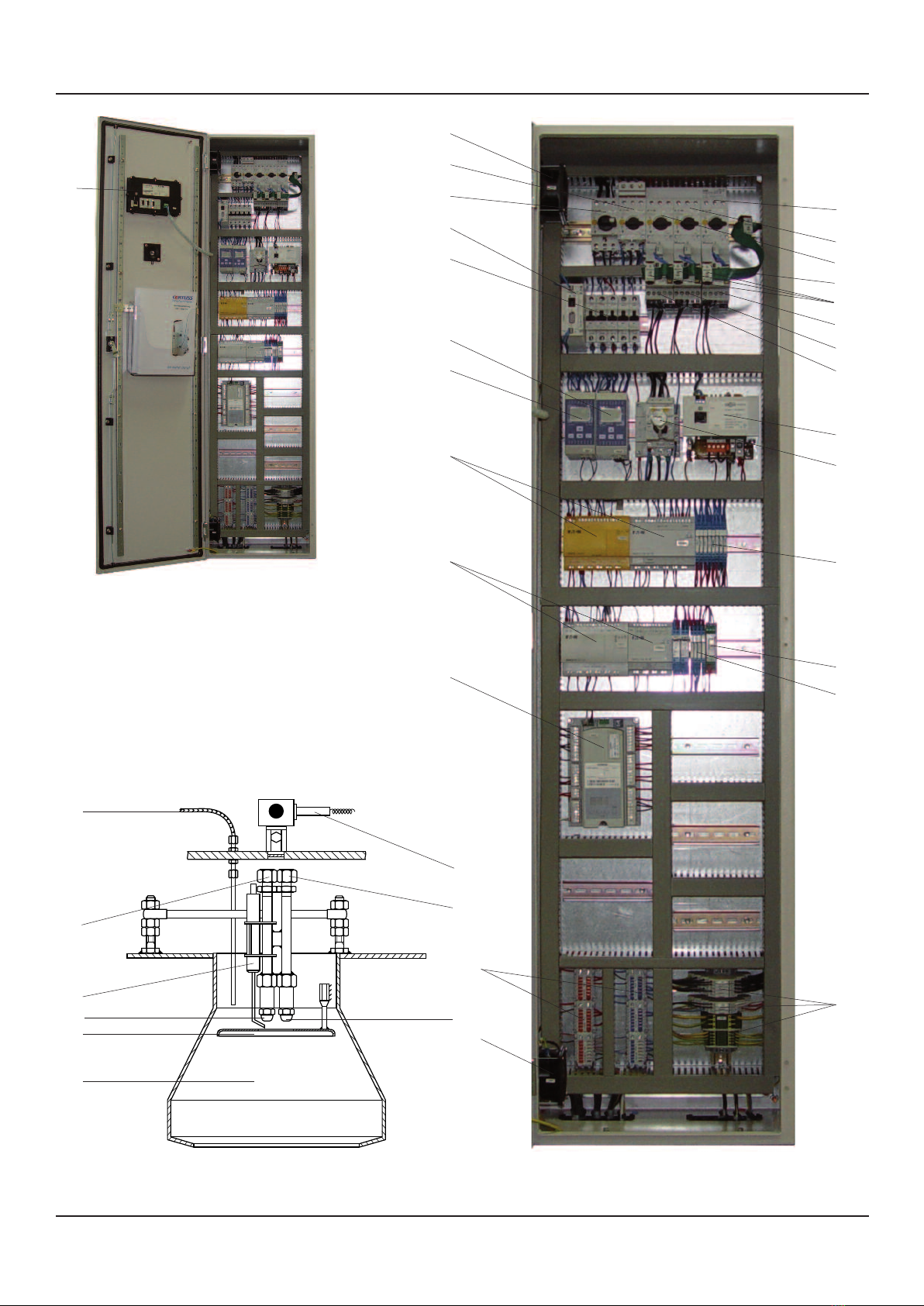
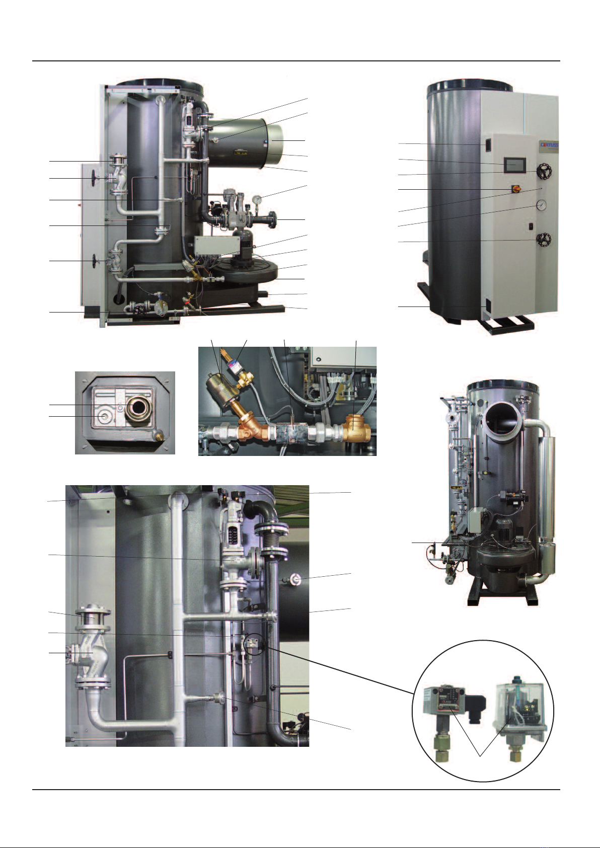
Übersicht Gasfeuerung und Rauchgasrückführung Survey gas firing and flue gas return
eitenansicht ohne eitenverkleidung
ide view without side cladding
Temperaturfühler, Drucksensor und Dampfdruckbegrenzer
Temperature sensor, pressure sensor and steam pressure
limiter
Vorderansicht
Front view
21
44
45
36
20
70
19
8
57
Rauchgasrückführung
Flue gas return
85
14
49
73
12
16
71
9
4
22
9
7
3
19
11
2
20
1
85
5
12
17
16
14
4 22 189
Anfahrleitung
tart-up line
Gebläse Teillastbrenner
Fan partial load burner
67
15
65
59
65
59
4b
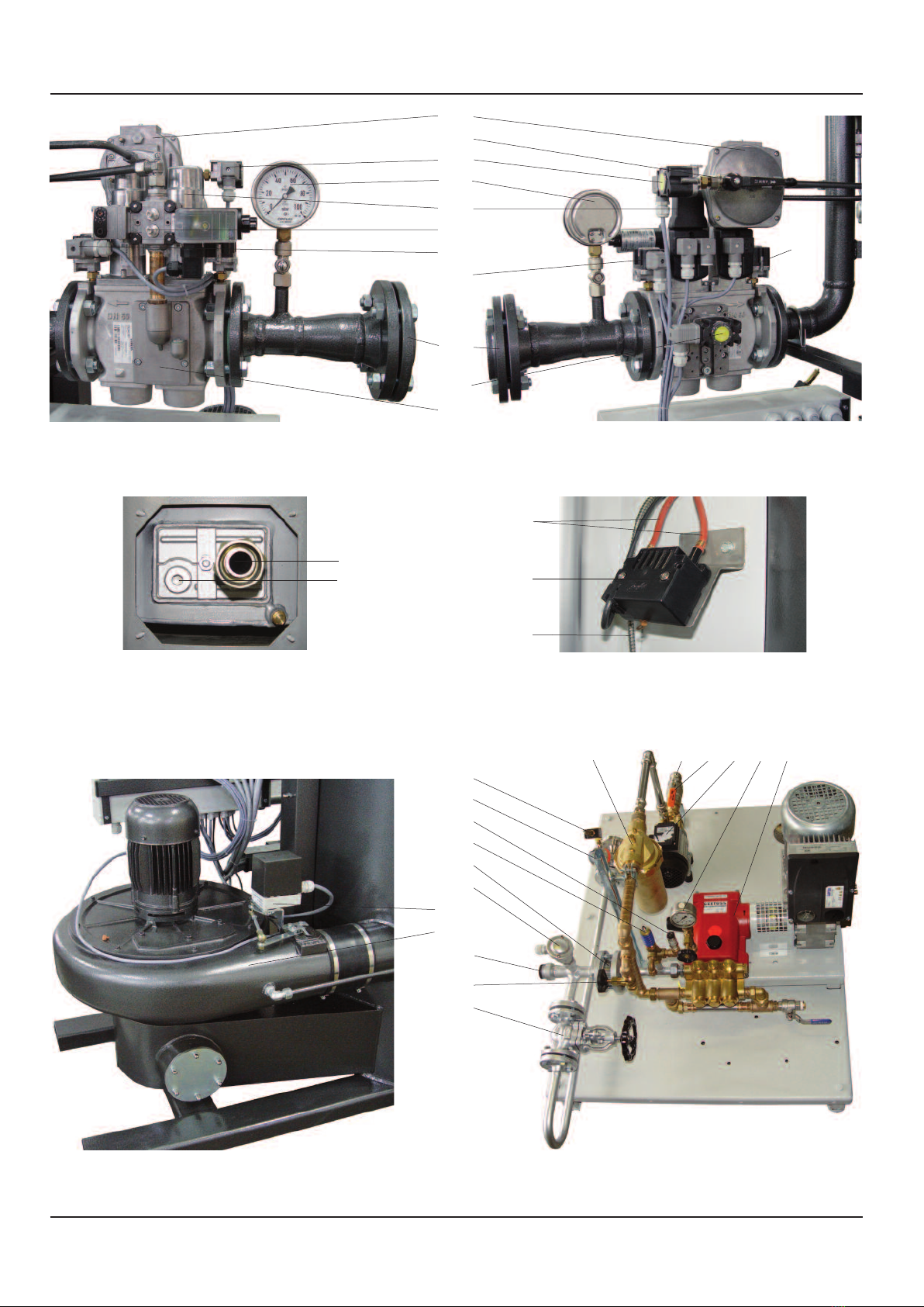
Übersicht Gasfeuerung und Rauchgasrückführung Survey gas firing and flue gas return
Gasstrecke Ansicht 1
Gas supply system, View 1
Gasstrecke Ansicht 2
Gas supply system, View 2
42
43
102
39
44
80
42
45
Gebläse mit tellmotor
Fan with servomotor
Wasserpumpe installiert mit Vordruckpumpe (Aufbaubeispiel)
Water pump installed with pre-pressure pump (exemplification)
61
66
40
41
79
9
7
58 87 13 8 54
75
77
56
10
55
57
81
72
36
Zündtrafo
Ignition transformer
33
35
6
Wassereintritt
Water inlet
52
53

5
Übersicht Gasfeuerung und Rauchgasrückführung Survey gas firing and flue gas return
1 Touchscreen
2 Hauptschalter mit Unterspannungsauslöser
3R
ückschlagventil Dampfaustritt (nur bei Ausrüstung Thermotimat)
4 Anfahrkolbenventil (nur bei Ausrüstung Thermotimat)
5 Optische lammüberwachung
6 Zündkabel
7 Automatisches Abschlämmventil (optional)
8 Manometer mit Nadelventil (optional)
9 3-Wege Pilotventil
10 ühler PT 100 Wassereintrittstemperatur
11 Dampfmanometer
13 Vordruckpumpe (optional)
14 ühler PT 100 Rauchgastemperaturbegrenzer
15 Dampfdruckbegrenzer
16 ühler PT 100 Dampftemperaturbegrenzer
17 Drucksensor Dampfdruckregelung
18 Rückschlagklappe Anfahrleitung
19 Anfahrventil
20 Hauptdampfventil
21 Sicherheitsventil
23 euerungsautomat
24 Motorschutzschalter Speisepumpe
25 Motorschutzschalter Gebläse
26 Motorschutzschalter Vordruckpumpe (optional)
27 Koppelrelais 230 V
28 Koppelrelais 24 V
29 Sicherheitsrelais 24 V
30 Motorschütz Gebläse
31 Motorschütz Vordruckpumpe (optional)
32 Schutzschalter Steuerspannung
33 Zündtransformator
35 Lichtleiterkabel
36 Gebläse Hauptbrenner
37
Motorschütz Gebläse Teillastbrenner (nur bei Rauch gas rück füh rung)
38 Motorschutzschalter Gebläse Teillastbrenner
(nur bei Rauchgas rückführung)
39 Luftdruckwächter Hauptbrenner
40 Hauptgasventile Gaskompakteinheit (a + b)
41 Gasdruckwächter min.
42 Gasdruckwächter max.
43 Gasdruckwächter Dichtheitskontrolle
44 Gasmanometer mit Druckknopfventil
45 Gasanschluss
46 Brenner (Seite 6)
47 Stauscheibe (Seite 6)
48 Sicherungselemente
49 Rauchgasanschluss
50 Heizschlange (Seite 4)
51 Verdampferteil (Seite 4)
52 Wassereintritt
53 Reinigungsstopfen
54 Wasserpumpe mit Motor
55 Wasserpumpendruckanschluss
56 Rückschlagventil Wassereintritt
57 Abschlämmventil
58 Speisewasseranschluss
59 Gebläse Teillastbrenner (nur bei Rauchgasrückführung)
60 Ionisationselektrode Hauptflamme (Seite 6)
61 Heißwasserfilter
62 Easy-Safety mit Erweiterung
63 Easy 822 mit Erweiterung
64 Teillastbrenner
65
Luftdruckwächter Teillastbrenner (nur bei Rauchgasrückführung)
66 Gasventil Teillastbrenner mit Gasdruckregler
67 Stellklappe Rauchgasrückführung (nur bei Rauchgasrückführung)
68 Rohr Teillastbrenner (Seite 6)
69 Ionisationselektrode Teillastbrenner (Seite 6)
70 Typenschild Heizsystem
71 Elektrounterverteilung/Stromanschluss
72 Luftstellklappe mit Stellmotor
73 Typenschild Dampfautomat
74 Klemmleiste
75 Wasservordrucksensor
76 Potentialverteiler
77 Wasserpumpenvordruck-Überströmventil
78 Speisewasserbehälter (Seite 4)
79 Gas-Luft-Verhältnisregler
80 Antrieb Sicherheitsgasabsperrung
81 Probeentnahmeventil
82 Rauchgastemperaturbegrenzer
83 Dampftemperaturbegrenzer
84 Steuertrafo
85 Lüfter für Schaltschrank
86 Dampftrockner (Seite 4)
87 Absperrventil
88 Kondensatableiter mit Schmutzfänger (Seite 4)
95 Zündelektrode (Seite 6)
98 Gasfilter (Seite 4)
102 3-Wege-Prüfhahn Luftdruckwächter
106 Luftdruckregler (nur bei Rauchgasrückführung)
107 Manometerprüfhahn
108 Rückschlagventil Dampftrockner (nur bei Mehrfachanlagen)
1 Touch screen
2 Main switch with undervoltage release
3 Return valve steam outlet (only for Thermotimat equipment)
4 Start-up piston valve (only for Thermotimat equipment)
5 Optical flame control
6 Ignition cable
7 Automatic blowdown valve (optional)
8 Manometer with needle valve (optional)
9 3-way pilot valve
10 Sensor PT 100 water inlet temperature
11 Steam pressure gauge
13 Pre-pressure pump (optional)
14 Sensor PT 100 flue-gas temperature limiter
15 Steam pressure limiter
16 Sensor PT 100 steam temperature limiter
17 Pressure sensor steam pressure controlling
18 Check valve start-up piping
19 Start-up valve
20 Main steam valve
21 Safety valve
23 iring control automat
24 Motor circuit breaker feed pump
25 Motor protection switch fan
26 Motor circuit breaker admission pressure pump (optional)
27 Coupling relay 230 V
28 Coupling relay 24 V
29 Safety relay 24 V
30 Motor contactor fan
31 Motor contactor pre-pressure pump (optional)
32 Circuit breaker control voltage
33 Ignition transformer
35 Light guide cable
36 an main burner
37 Motor contactor partial load burner (only with flue gas return)
38 Motor protection switch fan partial load burner
(only with flue gas return) optional
39 Air pressure controller main burner
40 Main gas valves (gas compact unit)
41 Gas pressure controller min.
42 Gas pressure controller max.
43 Gas pressure detector leak monitoring
44 Gas pressure gauge with push button valve
45 Gas connection
46 Burner (page 6)
47 Baffle plate (page 6)
48 use elements
49 lue gas connection
50 Heating coil (page 4)
51 Evaporator (page 4)
52 Water inlet
53 Cleaning plug
54 Water pump with motor
55 Water pump pressure connection
56 Return outlet water inlet
57 Drain valve
58 eed water connection
59 an partial load burner (only with flue gas return) optional
60 Ionisation electrode main flame (page 6)
61 Hot water filter
62 Easy safety with extension
63 Easy 822 with extension
64 Part-load burner
65 Gas pressure regulator part-load burner
66 Gas valve part-load burner
67 Control damper flue-gas recycling (only for flue-gas recycling)
68 Tube part-load burner (page 6)
69 Ionisation electrode part-load burner (page 6)
70 Type plate heating system
71 Electrical sub-distribution/power connection
72 Adjustable air flap with servomotor
73 Type plate steam generator
74 Terminal strip
75 Water admission pressure sensor
76 Potential distributor
77 Water pump pre-pressure-overflow valve
78 eed water tank (page 4)
79 Gas-air-ratio regulator
80 Drive gas safety shut-off device
81 Sampling valve
82 lue-gas temperature limiter
83 Steam temperature limiter
84 Control transformer
85 an for switch cabinet
86 Steam drier (page 4)
87 Shut-off valve
88 Steam trap with dirt trap (Page 4)
95 Ignition electrode (page 6)
98 Gas filter (page 4)
102 3-way test cock air pressure controller
106 Air pressure regulator (only for flue-gas recycling)
107 Manometer test cock
108 Return valve steam dryer (only at multiple systems)

6
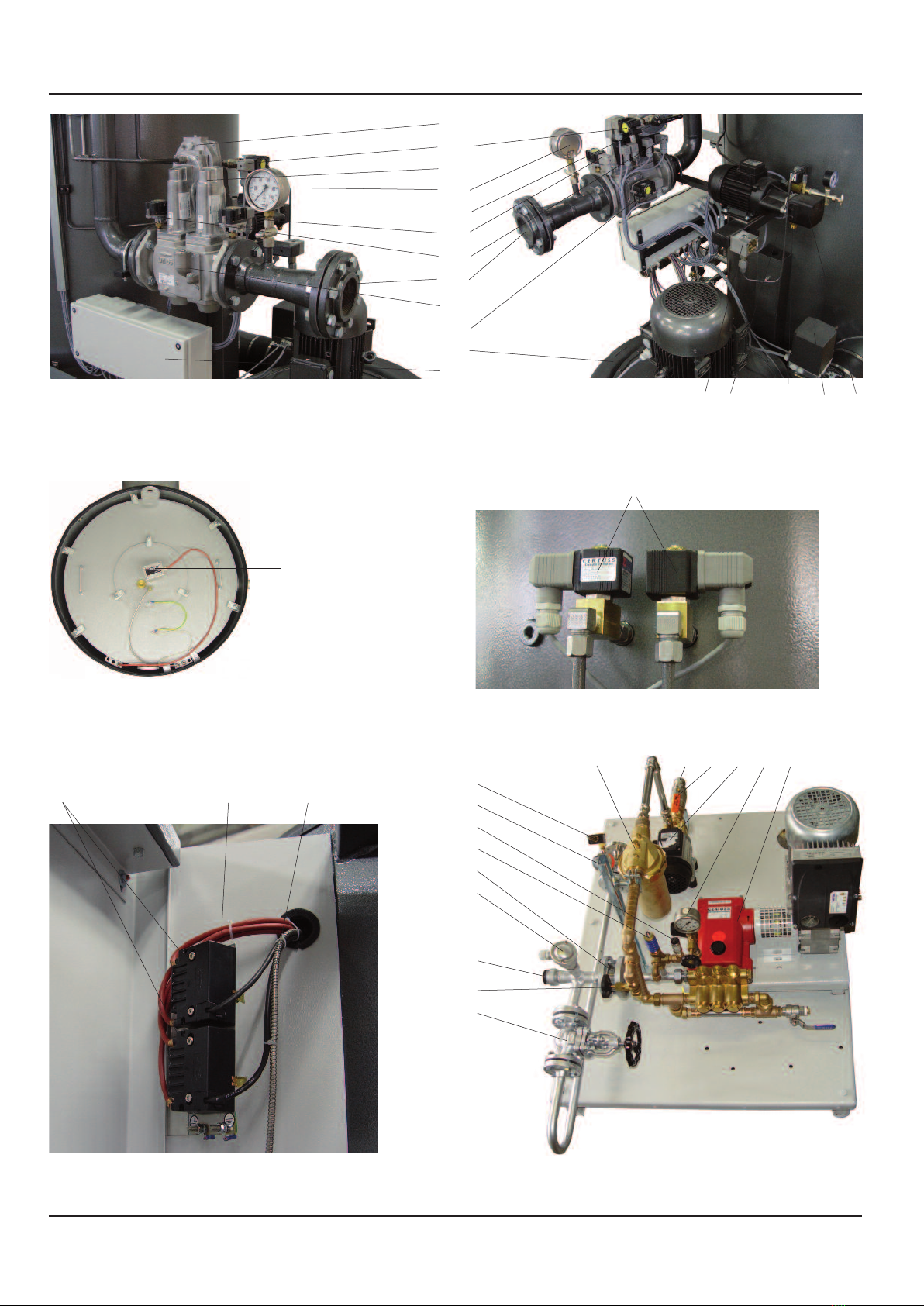
Übersicht Gasfeuerung und Rauchgasrückführung Survey gas firing and flue gas return
chaltschrank Gasfeuerung
Control cabinet gas firing
1
38
24
Brenner Gas
Burner gas
69
46
68
47
64
95
60
35
26
25
37
31
30
32
103
85
48
83
82
62
63
23
76
85
84
2
27
74
chaltschrank Gasfeuerung
Control cabinet gas firing
28
29
104
104
105
6a
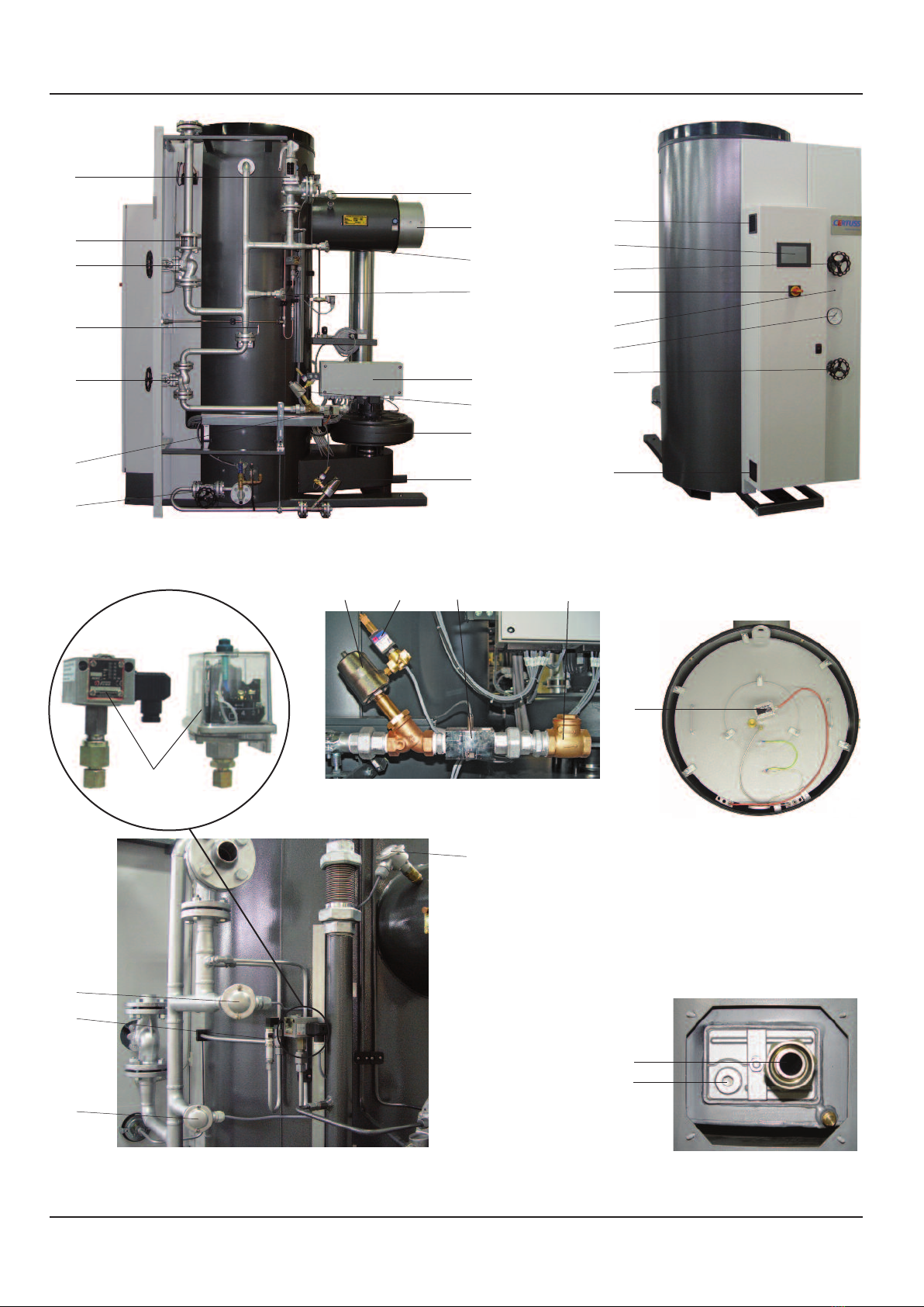
Übersicht Ölfeuerung und Rauchgasrückführung Survey oil firing and flue gas return
eitenansicht
Lateral view
21
49
14
36
3
20
70
19
22
71
Wassereintritt
Water inlet
52
53
Dampfautomat ohne Kunststoffdeckel
team generator without plastic cover
34
Vorderansicht
Front view
85
19
11
2
20
1
85
5
Temperaturfühler, Drucksensor und Dampfdruckbegrenzer
Temperature sensor, pressure sensor and steam pressure limiter
15
700-1800 500-600
12
17
16
14
7
57
4
12
16
4 22 189
Anfahrleitung
tart-up line

6b
Übersicht Ölfeuerung und Rauchgasrückführung Survey oil firing and flue gas return
Luftdruckwächter Hauptbrenner
Air pressure controller main burner
102
(Universal 700 - 1800)
39
Ölmagnetventile
Oil solenoid valves
Ölpumpe mit Motor
Oil pump with motor
91
14
97
72
Rauchgasrückführung
Flue gas return
67
Wasserpumpe installiert mit Vordruckpumpe (Aufbaubeispiel)
Water pump installed with pre-pressure pump (exemplification)
61
9
7
58 87 13 8 54
75
77
56
10
55
57
81
72
36
92
Zündtrafo
Ignition transformer
33
35
6
92
93

7
Übersicht Ölfeuerung und Rauchgasrückführung Survey oil firing and flue gas return
1 Touchscreen
2 Hauptschalter mit Unterspannungsauslöser
3 Rückschlagventil Dampfaustritt (nur bei Ausrüstung
Thermotimat)
4 Anfahrkolbenventil (nur bei Ausrüstung Thermotimat)
5 Optische lammüberwachung
6 Zündkabel
7 Automatisches Abschlämmventil (optional)
8 Manometer mit Nadelventil (optional)
9 3-Wege Pilotventil (nur bei autom. Startentwässerung)
10 ühler PT 100 Wassereintrittstemperatur
11 Dampfmanometer
13 Vordruckpumpe (optional)
14 ühler PT 100 Rauchgastemperaturbegrenzer
15 Dampfdruckbegrenzer
16 ühler PT 100 Dampftemperaturbegrenzer
17 Drucksensor Dampfdruckregelung
18 Rückschlagklappe Anfahrleitung
19 Anfahrventil
20 Hauptdampfventil
21 Sicherheitsventil
23 euerungsautomat
24 Motorschutzschalter Speisepumpe
25 Motorschutzschalter Gebläse
26 Motorschutzschalter Vordruckpumpe (optional)
27 Koppelrelais 230 V
28 Koppelrelais 24 V
29 Sicherheitsrelais 24 V
30 Motorschütz Gebläse
31 Motorschütz Vordruckpumpe (optional)
32 Schutzschalter Steuerspannung
33 Zündtransformator
34 lammenwächter
35 Lichtleiterkabel
36 Gebläse Hauptbrenner
39 Luftdruckwächter Hauptbrenner
46 Brenner (Seite 8)
47 Stauscheibe (Seite 8)
48 Sicherungselemente
49 Rauchgasanschluss
50 Heizschlange (Seite 4)
51 Verdampferteil (Seite 4)
52 Wassereintritt
53 Reinigungsstopfen
54 Wasserpumpe mit Motor
55 Wasserpumpendruckanschluss
56 Rückschlagventil Wassereintritt
57 Abschlämmventil
58 Speisewasseranschluss
61 Heißwasserfilter
62 Easy-Safety mit Erweiterung
63 Easy 822 mit Erweiterung
67 Stellklappe Rauchgasrückführung (nur bei Rauchgasrückführung)
70 Typenschild Heizsystem
71 Elektrounterverteilung/Stromanschluss
72 Luftstellklappe mit Stellmotor
73 Typenschild Dampfautomat
74 Klemmleiste
75 Wasservordrucksensor
76 Potentialverteiler
77 Wasserpumpenvordruck-Überströmventil
78 Speisewasserbehälter (Seite 4)
81 Probeentnahmeventil
82 Rauchgastemperaturbegrenzer
83 Dampftemperaturbegrenzer
84 Steuertrafo
85 Lüfter für Schaltschrank
86 Dampftrockner (Seite 4)
87 Absperrventil
88 Kondensatableiter mit Schmutzfänger (Seite 4)
89 Motorschutzschalter Ölpumpe
90 Motorschütz Ölpumpe
91 Ölpumpe mit Motor
92 Ölmagnetventil
93 Ölleitungsanschluss
94 Ölbrennerdüse (Seite 8)
95 Zündelektrode (Seite 8)
96 Thermostat Rauchgasrückführung (optional)
97 Öldruckwächter
102 3-Wege-Prüfhahn Luftdruckwächter
107 Manometerprüfhahn
108 Rückschlagventil Dampftrockner (nur bei Mehrfachanlagen)
1 Touch screen
2 Main switch with undervoltage release
3 Return valve steam outlet (only for Thermotimat equipment)
4 Start-up piston valve (only for Thermotimat equipment)
5 Optical flame control
6 Ignition cable
7 Automatic blowdown valve (optional)
8 Manometer with needle valve (optional)
9 3-way pilot valve
10 Sensor PT 100 water inlet temperature
11 Steam pressure gauge
13 Pre-pressure pump (optional)
14 Sensor PT 100 flue-gas temperature limiter
15 Steam pressure limiter
16 Sensor PT 100 steam temperature limiter
17 Pressure sensor steam pressure controlling
18 Check valve start-up piping
19 Start-up valve
20 Main steam valve
21 Safety valve
23 iring control automat
24 Motor circuit breaker feed pump
25 Motor protection switch fan
26 Motor circuit breaker admission pressure pump (optional)
27 Coupling relay 230 V
28 Coupling relay 24 V
29 Safety relay 24 V
30 Motor contactor fan
31 Motor contactor pre-pressure pump (optional)
32 Circuit breaker control voltage
33 Ignition transformer
34 lame control
35 Light guide cable
36 an main burner
39 Air pressure controller main burner
46 Burner (page 8)
47 Baffle plate (page 8)
48 use elements
49 lue gas connection
50 Heating coil (page 4)
51 Evaporator (page 4)
52 Water inlet
53 Cleaning plug
54 Water pump with motor
55 Water pump pressure connection
56 Return outlet water inlet
57 Drain valve
58 eed water connection
61 Hot water filter
62 Easy safety with extension
63 Easy 822 with extension
67 Control damper flue-gas recycling (only for flue-gas recycling)
70 Type plate heating system
71 Electrical sub-distribution/power connection
72 Adjustable air flap with servomotor
73 Type plate steam generator
74 Terminal strip
75 Water admission pressure sensor
76 Potential distributor
77 Water pump pre-pressure-overflow valve
78 eed water tank (page 4)
81 Sampling valve
82 lue-gas temperature limiter
83 Steam temperature limiter
84 Control transformer
85 an for switch cabinet
86 Steam drier (page 4)
87 Shut-off valve
88 Steam trap with dirt trap (Page 4)
89 Motor protection switch oil pump
90 Motor contactor oil pump
91 Oil pump with motor
92 Solenoid valve oil
93 Oil connection
94 Oil burner injector (page 8)
95 Ignition electrode (page 8)
96 Thermostat flue gas return (optional)
97 Oil pressure controller
102 3-way-test cock air pressure controller
107 Manometer test cock
108 Return valve steam dryer (only at multiple systems)
8
Übersicht Ölfeuerung und Rauchgasrückführung Survey oil firing and flue gas return
Brenner Öl mit Flammenüberwachung UV-Zelle
Burner oil with flame detector UV cell
35
59
34
95
94 94
59
47
46
chaltschrank Ölfeuerung
Control cabinet oil firing
1
89
24
26
25
90
31
30
32
103
85
48
83
82
62
63
23
76
85
84
2
27
74
chaltschrank Ölfeuerung
Control cabinet oil firing
29
28
104
105
8a
Übersicht Kombiausführung Gas-/Ölfeuerung Survey combined version gas/oil firing
eitenansicht
Lateral view
Dampfaustritt
team outlet
Vorderansicht
Front view
21
49
44
45
36
20
70
19
57 85
19
11
2
20
1
85
5
20
15
700-1800 500-600
14
12
16
17
3
21
92
92
Rauchgasrückführung
Flue gas return
67
Wassereintritt
Water inlet
52
53
3
14
73
12
9
4
22
9
7
16
4 22 189
Anfahrleitung
tart-up line
8b
Übersicht Kombiausführung Gas-/Ölfeuerung Survey combined version gas/oil firing
Kombi Gasstrecke Ansicht 1
Comined version gas system view 1
Kombi Gasstrecke Ansicht 2
Combined version gas system view 2
42
102
44
9297 93
41
43
40
72
45
91
39
Zündtrafo
Ignition transformer
35
6
33
Dampfautomat ohne Kunststoffdeckel
team generator without plastic cover
34
36
71
79
80
Wasserpumpe installiert mit Vordruckpumpe (Aufbaubeispiel)
Water pump installed with pre-pressure pump (exemplification)
61
9
7
58 87 13 8 54
75
77
56
10
55
57
81
Ölmagnetventile
Oil solenoid valves
92

9
Übersicht Kombiausführung Gas-/Ölfeuerung Survey combined version gas/oil firing
1 Touchscreen
2 Hauptschalter mit Unterspannungsauslöser
3 Rückschlagventil Dampfaustritt (nur bei Ausrüstung
Thermotimat)
4 Anfahrkolbenventil (nur bei Ausrüstung Thermotimat)
5 Optische lammüberwachung
6 Zündkabel
7 Automatisches Abschlämmventil (optional)
8 Manometer mit Nadelventil (optional)
9 3-Wege Pilotventil (nur bei autom. Startentwässerung)
10 ühler PT 100 Wassereintrittstemperatur
11 Dampfmanometer
13 Vordruckpumpe (optional)
14 ühler PT 100 Rauchgastemperaturbegrenzer
15 Dampfdruckbegrenzer
16 ühler PT 100 Dampftemperaturbegrenzer
17 Drucksensor Dampfdruckregelung
18 Rückschlagklappe Anfahrleitung
19 Anfahrventil
20 Hauptdampfventil
21 Sicherheitsventil
23 euerungsautomat
24 Motorschutzschalter Speisepumpe
25 Motorschutzschalter Gebläse
26 Motorschutzschalter Vordruckpumpe (optional)
27 Koppelrelais 230 V
28 Koppelrelais 24 V
29 Sicherheitsrelais 24 V
30 Motorschütz Gebläse
31 Motorschütz Vordruckpumpe (optional)
32 Schutzschalter Steuerspannung
33 Zündtransformator
34 lammwächter
35 Lichtleiterkabel
36 Gebläse Hauptbrenner
39 Luftdruckwächter Hauptbrenner
40 Hauptgasventile Gaskompakteinheit (a + b)
41 Gasdruckwächter min.
42 Gasdruckwächter max.
43 Gasdruckwächter Dichtheitskontrolle
44 Gasmanometer mit Druckknopfventil
45 Gasanschluss
46 Brenner (Seite 10)
47 Stauscheibe (Seite 10)
48 Sicherungselemente
49 Rauchgasanschluss
50 Heizschlange (Seite 4)
51 Verdampferteil (Seite 4)
52 Wassereintritt
53 Reinigungsstopfen
54 Wasserpumpe mit Motor
55 Wasserpumpendruckanschluss
56 Rückschlagventil Wassereintritt
57 Abschlämmventil
58 Speisewasseranschluss
61 Heißwasserfilter
62 Easy-Safety mit Erweiterung
63 Easy 822 mit Erweiterung
67 Stellklappe Rauchgasrückführung (nur bei Rauchgasrückführung)
70 Typenschild Heizsystem
71 Elektrounterverteilung/Stromanschluss
72 Luftstellklappe mit Stellmotor
73 Typenschild Dampfautomat
74 Klemmleiste
75 Wasservordrucksensor
76 Potentialverteiler
77 Wasserpumpenvordruck-Überströmventil
78 Speisewasserbehälter (Seite 4)
79 Gas-Luft-Verhältnisregler
80 Antrieb Sicherheitsgasabsperrung
81 Probeentnahmeventil
82 Rauchgastemperaturbegrenzer
83 Dampftemperaturbegrenzer
84 Steuertrafo
85 Lüfter für Schaltschrank
86 Dampftrockner (Seite 4)
87 Absperrventil
88 Kondensatableiter mit Schmutzfänger (Seite 4)
89 Motorschutzschalter Ölpumpe
90 Motorschütz Ölpumpe
91 Ölpumpe mit Motor
92 Ölmagnetventil
93 Ölleitungsanschluss
94 Ölbrennerdüse (Seite 10)
95 Zündelektrode (Seite 10)
97 Öldruckwächter
98 Gasfilter (Seite 4)
102 3-Wege-Prüfhahn Luftdruckwächter
107 Manometerprüfhahn
108 Rückschlagventil Dampftrockner (nur bei Mehrfachanlagen)
1 Touch screen
2 Main switch with undervoltage release
3 Return valve steam outlet (only for Thermotimat equipment)
4 Start-up piston valve (only for Thermotimat equipment)
5 Optical flame control
6 Ignition cable
7 Automatic blowdown valve (optional)
8 Manometer with needle valve (optional)
9 3-way pilot valve
10 Sensor PT 100 water inlet temperature
11 Steam pressure gauge
13 Pre-pressure pump (optional)
14 Sensor PT 100 flue-gas temperature limiter
15 Steam pressure limiter
16 Sensor PT 100 steam temperature limiter
17 Pressure sensor steam pressure controlling
18 Check valve start-up piping
19 Start-up valve
20 Main steam valve
21 Safety valve
23 iring control automat
24 Motor circuit breaker feed pump
25 Motor protection switch fan
26 Motor circuit breaker admission pressure pump (optional)
27 Coupling relay 230 V
28 Coupling relay 24 V
29 Safety relay 24 V
30 Motor contactor fan
31 Motor contactor pre-pressure pump (optional)
32 Circuit breaker control voltage
33 Ignition transformer
34 lame control
35 Light guide cable
36 an main burner
39 Air pressure controller main burner
40 Main gas valves gas compact unit (a + b)
41 Gas pressure controller min.
42 Gas pressure controller max.
43 Gas pressure detector leak monitoring
44 Gas pressure gauge with push button valve
45 Gas connection
46 Burner (page 10)
47 Baffle plate (page 10)
48 use elements
49 lue gas connection
50 Heating coil (page 4)
51 Evaporator (page 4)
52 Water inlet
53 Cleaning plug
54 Water pump with motor
55 Water pump pressure connection
56 Return outlet water inlet
57 Drain valve
58 eed water connection
61 Hot water filter
62 Easy safety with extension
63 Easy 822 with extension
67 Control damper flue-gas recycling (only for flue-gas recycling)
70 Type plate heating system
71 Electrical sub-distribution/power connection
72 Adjustable air flap with servomotor
73 Type plate steam generator
74 Terminal strip
75 Water admission pressure sensor
76 Potential distributor
77 Water pump pre-pressure-overflow valve
78 eed water tank (page 4)
79 Gas-air-ratio regulator
80 Drive gas safety shut-off device
81 Sampling valve
82 lue-gas temperature limiter
83 Steam temperature limiter
84 Control transformer
85 an for switch cabinet
86 Steam drier (page 4)
87 Shut-off valve
88 Steam trap with dirt trap (Page 4)
89 Motor protection switch oil pump
90 Motor contactor oil pump
91 Oil pump with motor
92 Solenoid valve oil
93 Oil connection
94 Oil burner injector (page 10)
95 Ignition electrode (page 10)
97 Oil pressure controller
98 Gas filter (page 4)
102 3-way-test cock air pressure controller
107 Manometer test cock
108 Return valve steam dryer (only at multiple systems)

10
Übersicht Kombiausführung Gas-/Ölfeuerung Survey combined version gas/oil firing
Brenner Kombi
Burner combined version
93
46
95
47
34
95
94
35
chaltschrank Kombi
Control cabinet combined version
1
89
24
26
25
90
31
30
32
103
85
48
83
82
62
63
23
76
85
84
2
27
74
chaltschrank Kombi
Control cabinet combined version
29
28
105
104

11
ACHTUNG!
ür die Sicherheit und einwandfreie unktion die rot
hervorgehobenen Vorschriften und Hinweise in dieser
Betriebsanleitung besonders beachten.
Bei Nichtbeachtung entfallen alle Haftungs- und/oder
Gewährleistungsansprüche gegen den Hersteller.
1.1 Piktogramme
In dieser Betriebsanleitung werden folgende
Pikto gramme verwendet:
Dieses Piktogramm macht auf gefährliche
Situationen mit möglichen Personen- oder
Maschinenschäden aufmerksam.
Dieses Piktogramm macht auf gefährliche
Situationen durch elektrischen Strom aufmerk -
sam. Die auszuführenden Arbeiten dürfen nur
von einer Elektrofachkraft ausgeführt werden.
Dieses Piktogramm macht auf Gefahren durch
heiße Oberflächen aufmerksam.
Dieses Piktogramm macht auf nützliche
Ratschläge, Erläuterungen und Ergänzungen
zur Handhabung des Dampfautomaten
aufmerksam.
1.2 Bestimmungsgemäße Verwendung
Der Dampfautomat ist gebaut nach dem Stand der
Technik und den anerkannten sicherheitstechnischen
Regeln. Dennoch können bei unsachgemäßer Verwen -
dung Gefahren für Leib und Leben des Benutzers oder
Dritter sowie Beeinträchtigungen des Dampfautomaten
und anderer Sachwerte entstehen.
Der Dampfautomat ist ausschließlich zur Erzeugung von
Dampf bestimmt. Eine andere oder darüber hinaus -
gehende Benutzung gilt als nicht bestimmungsgemäß.
Zur bestimmungsgemäßen Verwendung gehört auch,
dass der Bediener des Dampfautomaten die Betriebs -
anleitung vollständig gelesen und verstanden hat und
die in der Betriebsanleitung beschriebenen Betriebs -
bedingungen/Vorgehens weisen beachtet werden.
Der Dampfautomat darf nur mit den auf dem
Typenschild angegebenen Grenzwerten für Dampfdruck
und Beheizungsleistung sowie dem angegebenen
Brennstoff betrieben werden.
1.2.1 Verwendbare Brennstoffe
1. Heizöl EL nach DIN 51603-EL-1
2. Gase der 1. Gasfamilie
Erdgas L und H
3. Gase der 3. Gasfamilie
Propan und Butan
4. Gase der 4. Gasfamilie
lüssiggas und Erdgas-Luft-Gemische
Bei anderen Brennstoffen Kesselhersteller befragen.
ATTENTION
To assure safety and proper function, particularly pay
attention to the instructions and advices marked in red.
In case of non-compliance, all liability and warranty
claims against the manufacturer will become void.
1.1 Pictograms
In these operating instructions, the following
pictograms are used:
This pictogram points out dangerous situations
with possible bodily injuries or machinery
breakdowns.
This pictogram points out dangerous situations
caused by electric current. The corresponding
works shall be effected only by a specialised
electrician.
This pictogram points out dangers caused by
hot surfaces.
This pictogram points out useful advice,
explanations and additional notes concerning
operation of the steam generator.
1.2 Appropriate use
The steam generator is constructed according to the
state-of-the-art of technology and the approved safety
regulations. However, dangers for life and physical
condition of the operator or third parties as well as
impairments of the steam generator or other material
assets may be the result of inappropriate use.
The steam generator is designed only for the
generation of steam. Another or ultra vires use is not
deemed to be appropriate.
Appropriate use also implies that the operator of the
steam generator has read and understood the
operation instruction thoroughly and completely, and
that the operation conditions/processes described in
the operating instructions are adhered to.
The steam generator shall be run only with the limit
values for steam pressure and heating capacity
indicated on the type plate and with the indicated fuel
as well.
1.2.1 Suitable fuels
1. uel oil EL according to DIN 51603-EL-1
2. Gases of the 1st gas family
natural gas L and H
3. Gases of the 3rd gas family
propane und butane
4. Gases of the 4th gas family
liquid gas and natural gas-air mixtures
or other fuels, please consult the manufacturer.
1 Allgemeines 1 General notes

12
1.3 General Regulations
1.3.1 Federal Republic of Germany
The steam generator is manufactured and equipped
according to Directive 2014/68/EU of the European
Parliament and Council of 15th of May 2014 and has a
CE mark.
The required Declarations of Conformity are issued for
each steam generator.
The following standards and regulations are taken into
account:
1. TRD (Technical Rules for Steam Boilers), AD2000
and parts of the DIN EN 12952.
2. DIN EN 267, DIN EN 676
All further standards according to DIN-EN, DIN-ISO,
DIN-VDE, VdTÜV material data sheets and VdTÜV
technical bulletins and agreements.
3. Ordinance on Industrial Safety and Health -
BetrSichV of June 01, 2015 and Technical
Regulations on Industrial Safety and Health - TRBS
4. Technical connection requirements (TAB) gas
supplier
5. Technical connection requirements (TAB) power
supplier
6. Technical connection requirements (TAB) water
supplier
7. ederal Immission Protection Law and ederal State
proceeding regulations.
8. ederal state building inspection regulations
9. Regulations of the Employer´s Liability Insurance
Association.
10. In general, all regulations of technology are applied
1.3.2 Other EU members
or installation and operation, the national regulations
of the Member States have to be observed.
1.3.3 Non-EU members
CERTUSS steam generators are specially authorised in
many countries outside of the EU. or installation and
operation, the national regulations are applied.
Have safety-specific inspections carried out
annually and recurrently in accordance with
national regulations by approved inspection
agency or by an authorized customer service.
1 Allgemeines 1 General notes
1.3 Allgemeine Vorschriften
1.3.1 Bundesrepublik Deutschland
Der Dampfautomat ist nach der Richtlinie 2014/68/EU
des Europäischen Parlaments und des Rates vom 15.
Mai 2014 hergestellt und ausgerüstet und hat ein CE-
Kennzeichen.
Die erforderlichen Konformitätserklärungen werden für
jeden Dampfautomaten ausgestellt.
Nachstehende Normen und Vorschriften sind berück -
sichtigt:
1. TRD, AD2000 und Teile der DIN EN 12952.
2. DIN EN 267, DIN EN 676
Alle weiteren Normen nach DIN-EN, DIN-ISO, DIN-
VDE sowie VdTÜV-Werkstoffblätter und VdTÜV-
Merkblätter und Vereinbarungen.
3. Betriebssicherheitsverordnung – BetrSichV vom
01. Juni 2015 und Technische Richtlinien für
Betriebssicherheit-TRBS
4. Technische Anschlussbedingungen (TAB)
Gasversorger
5. Technische Anschlussbedingungen (TAB)
Elektroversorger
6. Technische Anschlussbedingungen (TAB)
Wasserversorger
7. Bundes-Immissionsschutzgesetz sowie Länder-
Durchführungsverordnungen
8. Länder-Bauaufsichtsvorschriften
9. Berufsgenossenschaftliche Vorschriften
10. Im Übrigen gemäß den Regeln der Technik
1.3.2 Andere EG-Mitgliedsstaaten
ür die Aufstellung und den Betrieb sind die nationalen
Vorschriften der Mitgliedsländer zu beachten.
1.3.3 änder außerhalb der EU
CERTUSS Dampfautomaten sind in vielen Ländern
außerhalb der EU besonders zugelassen. ür die
Aufstellung und den Betrieb gelten die nationalen
Vorschriften.
Sicherheitstechnische Prüfungen jährlich und
wiederkehrend je nach nationalen Vorschriften
durch zugelassene Überwachungsstelle oder
durch einen autorisierten Kundendienst
veranlassen.
13
2.1 Staff requirements
Risk of accident!
Operations on the steam generator shall only
be effected by persons who are authorised for
it because of their training and qualification.
urthermore, the persons have to be instructed
for these operations by the operator.
Connection, maintenance and repair workings shall only
be effected by qualified and trained specialists.
Persons working on the steam generator must take care
not to endanger themselves or others by their activity.
2.2 Obligations of the operator
Risk of accident!
The steam generator may cause danger when
operated improperly or in improper condition.
The operator is obligated to use the steam generator
only in perfect condition. Danger zones arising between
the generator and the customer´s equipment have to
be protected by the operator.
2.3 In the Federal Republic of Germany
In accordance with the Ordinance on Industrial Safety
and Health BetrSichV § 3, a danger judgement for the
dangers which may result from the use of the steam
plant and from the work stations is required.
2.4 Classification in danger classes according to
PEO 2014/68/EU
Other maximum permissible operating
pressures between 8 and 32 bars possible.
2 Safety
2.1 Anforderungen an Personen
Unfallgefahr!
Arbeiten am Dampfautomaten dürfen nur von
Personen ausgeführt werden, die aufgrund
ihrer Ausbildung und Qualifikation dazu
berechtigt sind. Außerdem müssen die
Personen vom Betreiber dazu beauftragt sein.
Anschluss-, Instandhaltungs- und Reparaturarbeiten
dürfen nur von ausgebildetem achpersonal
durchgeführt werden.
Personen, die am Dampfautomaten tätig sind, haben
darauf zu achten, dass sie weder sich noch andere
durch ihre Tätigkeit gefährden.
2.2 Pflichten des Betreibers
Unfallgefahr!
Von dem Dampfautomaten gehen Gefahren
aus, wenn er unsachgemäß oder nicht in
ordnungsgemäßem Zustand betrieben wird.
Der Betreiber ist verpflichtet, den Dampf auto maten nur
in einwandfreiem Zustand zu betreiben.
Gefahrenstellen, die zwischen dem Dampfautomaten
und kundenseitigen Einrichtungen entstehen, müssen
vom Betreiber gesichert werden.
2.3 In der Bundesrepublik Deutschland
Gemäß Betriebssicherheitsverordnung – BetrSichV § 3 –
ist eine Gefährdungsbeurteilung der durch die
Benutzung der Dampfanlage und durch die
Arbeitsumgebung hervorgerufenen Gefahren
erforderlich.
2.4 Einteilung nach DGR 2014/68/EU in
Gefahrenklassen
Es sind auch andere max. zulässige Betriebs -
überdrücke zwischen 8 und 32 bar möglich.
2 Sicherheit
Typ CERTUSS Heizfläche
m2
Druck
bar
Inhalt
ltr.
Produkt
PS x V
Kategorie
Universal
500 / 600 10,3
10
16
20
25
32
42,9
429
686,4
858
1072
1372,8
III
III
III
III
III
Universal
700 / 850 16,4
10
16
25
32
103,5
1035
1656
2587
3312
III
III
III
IV
Universal
1000 / 1300 23,7
10
16
25
32
155,7
1557
2491,7
3892,5
4982,4
III
III
IV
IV
Universal
1500 / 1800 30,4
10
16
25
32
218
2180
3488
5450
6976
III
IV
IV
IV
Type CERTUSS heating
surface m2
pressure
bar
content
ltr.
product
PS x V
Category
Universal
500 / 600 10,3
10
16
20
25
32
42,9
429
686,4
858
1072
1372,8
III
III
III
III
III
Universal
700 / 850 16,4
10
16
25
32
103,5
1035
1656
2587
3312
III
III
III
IV
Universal
1000 / 1300 23,7
10
16
25
32
155,7
1557
2491,7
3892,5
4982,4
III
III
IV
IV
Universal
1500 / 1800 30,4
10
16
25
32
218
2180
3488
5450
6976
III
IV
IV
IV
14
2.5 Verantwortliche Personen bestimmen und
einweisen
Nur geschultes oder unterwiesenes Personal einsetzen.
Zuständigkeiten des Personals für das Bedienen, War -
ten, Instandsetzen klar festlegen.
Regelmäßig das sicherheits- und gefahrenbewusste
Arbeiten des Personals unter Beachtung der Betriebs -
anleitung kontrollieren.
Das mit Tätigkeiten am Dampfautomaten beauftragte
Per sonal muss vor Arbeitsbeginn die Betriebsanleitung,
und hier besonders das Kapitel
„Sicherheitsmaßnahmen“, sowie geltende Vorschriften
gelesen und verstanden haben.
Die Betriebsanleitung und geltende Vorschriften so
aufbewahren, dass sie dem Bedien- und
Wartungspersonal zugänglich sind.
Ergänzend zur Betriebsanleitung
allgemeingültige gesetzliche und sonstige
verbindliche Rege lungen zur Unfallverhütung
und zum Umwelt schutz beachten und
anweisen!
2.6 Elektrische/elektronische Einrichtungen
Beim Kontakt mit unter Spannung stehenden Leitungen
oder Bauteilen besteht Lebensgefahr!
Vor Arbeiten an elektrischen/elektronischen Einrich tun -
gen muss der Dampfautomat vom Netz getrennt
werden.
Den Dampfautomaten regelmäßig überprüfen.
est gestell te Mängel oder Störungen sofort beheben.
Den Dampfautomaten bis zum Beheben der Mängel
abschalten.
Sind Arbeiten an spannungsführenden Teilen
notwendig, eine zweite Person hinzuziehen, die im
Notfall die Span nungsversorgung ausschaltet. Den
Arbeitsbereich ab sperren und mit einem Warnschild
versehen. Nur spannungsisoliertes Werkzeug benutzen.
Sicherungen nicht reparieren oder überbrücken. Nur die
vom Hersteller vorgesehenen Sicherungen einsetzen.
Im Schaltschrank der elektrischen Steuerung
des Dampfautomaten keine externen
Zusatzsteuerungen oder Abgriffe anschließen!
Es sind nur original CERTUSS-Zusatzeinrich -
tungen zugelassen.
Bei remdinstallationen erlöschen Kessel -
zulassung und Garantie!
2.5 Determine and instruct persons in charge
Only employ a trained or instructed staff. Determine
clearly the responsibilities of the staff for operation,
maintenance, repairing.
Check regularly if the staff work safety-conscious and
danger-aware in compliance with the operating
instructions.
The staff charged with operations on the steam
generator has to have read and understood the
operating instruction - and here in particular the
chapter “safety measures” as well as the applicable
regulations before starting work.
Keep operating instructions and applicable regulations
available for the service and maintenance staff.
In addition to the operating instructions,
observe and advice general legal and other
binding regulations related to accident
prevention and environmental protection.
2.6 Electrical/Electronic equipment
There is danger of life when contacting live wires or
construction elements!
Before working on electrical/electronical equipment,
the steam generator has to be disconnected from the
power supply.
Check the steam generator regularly. Eliminate
detected defects or faults immediately. Shut off the
steam generator until the defects are eliminated.
If operations on live parts are necessary, call in a second
person who can switch off the power supply in case of
emergency. Close off the working area and install a
danger sign. Use only tools which are insulated against
voltage.
Do not repair or bridge fuses. Use only the fuses
intended to be inserted by the manufacturer.
Do not connect any external supplementary control
s
ystems or taps in the control cabinet of the
electrical control system of the steam generator!
Only original CERTUSS supplementary devices
are approved and permitted.
In the case of external installations the boiler
approval and guarantee become invalid!
2 Sicherheit 2 Safety
This manual suits for next models
8
Table of contents
Other CERTUSS Iron manuals


