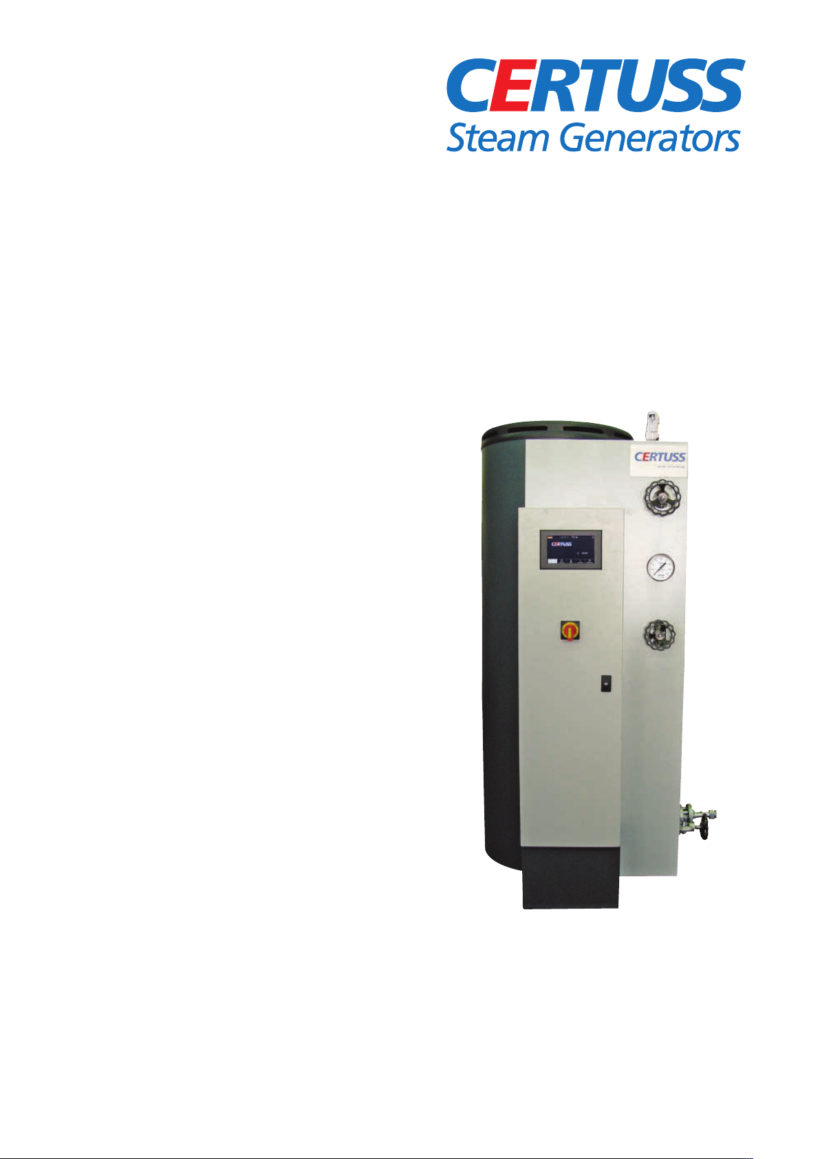
CERTUSS Junior 80 - 400 TC User manual
D /GB
D /GB
Operati g I structio s
Betriebsa leitu g
Ju ior 80 – 400 TC
The power of steam

2
Seite
Inhaltsverzeichnis 2 – 3
Übersicht
Fotos Seitenansicht Junior 80 – 400 4
Detailfotos und Schaltschrank mit Steuerung 5 – 6
Ausrüstungsliste 7
Schemazeichung Dampfautomat/Brenner 8
1 Allgemeines
1.1 Piktogramme 9
1.2 Bestimmungsgemäße Verwendung 9
1.3 Allgemeine Vorschriften 10
2 Sicherheit
2.1 Anforderungen an Personen 11
2.2 Pflichten des Betreibers 11
2.3 In der Bundesrepublik Deutschland 11
2.4 inteilung nach DGRL 11
2.5 Verantwortliche Personen 12
2.6 lektrische/elektronische inrichtungen 12
2.7 Sicherheit bei Wartungsarbeiten 13
2.8 rsatzteile 13
2.9 ntsorgung von Schmier- und
Problem stoffen 13
2.10 Mögliche elektrische Netzversorgung 14
3 Funktion
3.1 Funktionsbeschreibung Dampfautomat 15
3.2 Beschreibung der Gasfeuerung 16 – 17
3.3 Beschreibung Gasfeuerung mit
Rauchgasrückführung 18
3.4 Beschreibung der Ölfeuerung 19
3.5 Beschreibung Ölfeuerung mit
Rauchgasrückführung 19
3.6 Betrieb mit Thermotimat 20 – 21
3.7 Betrieb ohne manuellen ingriff bis 24h 22
3.8 Betrieb ohne manuellen ingriff bis 72h 23
4 Touchscreen
4.1 Symbolerklärungen 24
4.2 Sprachen 25
5 Erstmalige Inbetriebnahme
5.1 Installation 26
5.2 Inbetriebnahme 27 – 29
6 Starten und Abschalten
6.1 Manuelles Starten/Abschalten 30 – 35
6.2 Thermotimat aktivieren/programmieren 35 – 38
7 Meldungen
7.1 Warnmeldungen 39 – 43
7.2 instellungen programmieren 44
7.3 Störabschaltungen und deren Anzeigen 45
Technische Änderungen vorbehalten.
Page
Table of Contents 2 – 3
Survey
Photos side view Junior 80 – 400 4
Detailed photos and control cabinet
with control system 5 – 6
quipment list 7
Schematic drawing of steam generator/burner 8
1 General notes
1.1 Pictograms 9
1.2 Appropriate use 9
1.3 General prescriptions 10
2 Safety
2.1 Staff requirements 11
2.2 Obligations of the operator 11
2.3 In the Federal Republic of Germany 11
2.4 Classification according to DGRL 11
2.5 Determine and instruct persons 12
2.6 lectrical/electronical devices 12
2.7 Safety during maintenance works 13
2.8 Spare parts 13
2.9 Disposal of lubricants and problematic
substances 13
2.10 Selection of electrical power supply 14
3 Function
3.1 Description steam generator 15
3.2 Description of the gas firing 16 – 17
3.3 Description gas firing with flue gas return 18
3.4 Description of the oil firing 19
3.5 Description oil firing with flue gas return 19
3.6 Operation with Thermotimat 20 – 21
3.7 Operation without manual intervention up
to 24 hours 22
3.8 Operation without manual intervention up
to 72 hours 23
4 Touchscreen
4.1 Symbol explanations 24
4.2 Languages 25
5 First commissioning
5.1 Installation 26
5.2 First starting 27 – 29
6 Starting and stopping
6.1 Manual starting/switching off 30 – 35
6.2 Activating/programming Thermotimat 35 – 38
7 Messages
7.1 Function indications 39 – 43
7.2 Programming settings 44
7.3 Fault shut-downs and their displays 45
Technical specifications are subject to change.
Inhaltsverzeichnis Table of Contents

3
Seite
8 Prüfung Dampfanlage
8.1 Betriebsbedingungen Speisewasser 46
8.2 Prüfanweisungen für die Dampfanlage 46
8.3 Wassermangelsicherung prüfen 47 – 48
8.4 Sicherheitsventil oder Dampfdruck-
begrenzer prüfen 49 – 50
8.5 Flammüberwachung prüfen 51
9 Wartung Dampfanlage
9.1 Wartungsanweisungen 52 – 53
9.2 ntwässerung bei Frostgefahr 54 – 55
9.3 Konservierung bei längerem Stillstand 56 – 57
9.4 Kesselsteinansatz entfernen 58 – 60
9.5 instellbeispiele Dampfdruckregelung 61
9.6 Heizsystem wechseln 62 – 63
9.7 Heizsystem entrußen 64 – 65
9.8 Messanleitung Brennereinstellung 66 – 67
10 Wasserpumpe
10.1 Wasserpumpe 80 – 200 TC / 10 – 32 bar 68 – 69
10.2 Wasserpumpe 250 – 300 TC / 10 – 32 bar 70 – 71
10.3 Wasserpumpe 350 – 400 TC / 10 – 32 bar 72 – 73
11 Prüfung und Wartung Wasserpumpe
11.1 Hinweise 74
11.2 Wartung 74
11.3 Instandsetzung 74
12 Technische Daten
12.1 Maße / Gewichte 76
12.2 Leistungsdaten 76
13 Anschlüsse
13.1 Anschluss- und instelldaten 77
13.2 Gas-Anschluss 78
13.3 Öl-Anschluss 79
13.4 Rauchgas-Anschluss 80
14 Physikalische Werte
14.1 Umrechnungstabelle Wasserhärte 80
14.2 Abgasmenge 81
14.3 Anforderung an Kesselspeisewasser 81
15 Feuerungsautomat
15.1 Zulassungen 82
15.2 Besondere Merkmale 82
15.3 Funktions- und Störanzeigen 82
15.4 Flammenstromanzeige 82 – 83
Technische Änderungen vorbehalten.
Page
8 Control steam plant
8.1 Operation conditions for feed water 46
8.2 Testing instructions for steam plant 46
8.3 Check water shortage safety device 47 – 48
8.4 Checking the safety valve or the steam
pressure limiter 49 – 50
8.5 Checking the flame monitoring 51
9 Maintenance steam plant
9.1 Maintenance instructions 52 – 53
9.2 Draining in danger of frost 54 – 55
9.3 Preservation in case of longer standstill 56 – 57
9.4 Remove scale deposits 58 – 60
9.5 Setting examples for steam pressure controlling 61
9.6 Change heating system 62 – 63
9.7 Desoot heating system 64 – 65
9.8 Measuring instruction burner adjustment 66 – 67
10 Water pump
10.1 Water pump 80 – 200 TC / 10 – 32 bar 68 – 69
10.2 Water pump 250 – 300 TC / 10 – 32 bar 70 – 71
10.3 Water pump 350 – 400 TC / 10 – 32 bar 72 – 73
11 Control and maintenance water pump
11.1 Notices 74
11.2 Maintenance 74
11.3 Repairing 74
12 Tecnical data
12.1 Measurements / Weights 76
12.2 Performance data 76
13 Connections
13.1 Connection and adjustment data 77
13.2 Gas connection 78
13.3 Oil connection 79
13.4 Flue gas connection 80
14 Physical values
14.1 Water hardness calculation table 80
14.2 xhaust gas quantity 81
14.3 Requirements for steam generator feed water 81
15 Firing control automat
15.1 Firing control automat approvals 82
15.2 Special features 82
15.3 Function and malfunction indications 82
15.4 Flame signal indication 82 – 83
Technical specifications are subject to change.
Inhaltsverzeichnis Table of Contents

Junior 150 – 400 Öl
Junior 150 – 400 oil
Junior 150 – 400 Gas
Junior 150 – 400 gas
Junior 80 – 120 Gas
Junior 80 – 120 gas
Junior 80 – 120 Öl
Junior 80 – 120 oil
49
4
Übersicht Survey
21
16 15 73
17
65
9
4
7
57
6
20
3
19
6
20
17
19
21
16
73
15
49
9
7
57
49
21
15
16
73
17
9
4
7
57
6
20
19
39
17
19
21
16 73
15
49
9
7
57
10
4
52
3
44
4
45
40
52
3
52
65
44
45
40
41
33
77
10
75
70
36
9
33
77
10
75
9
36
33
77
10
75
9
36 36
9
52
20
3
33
5
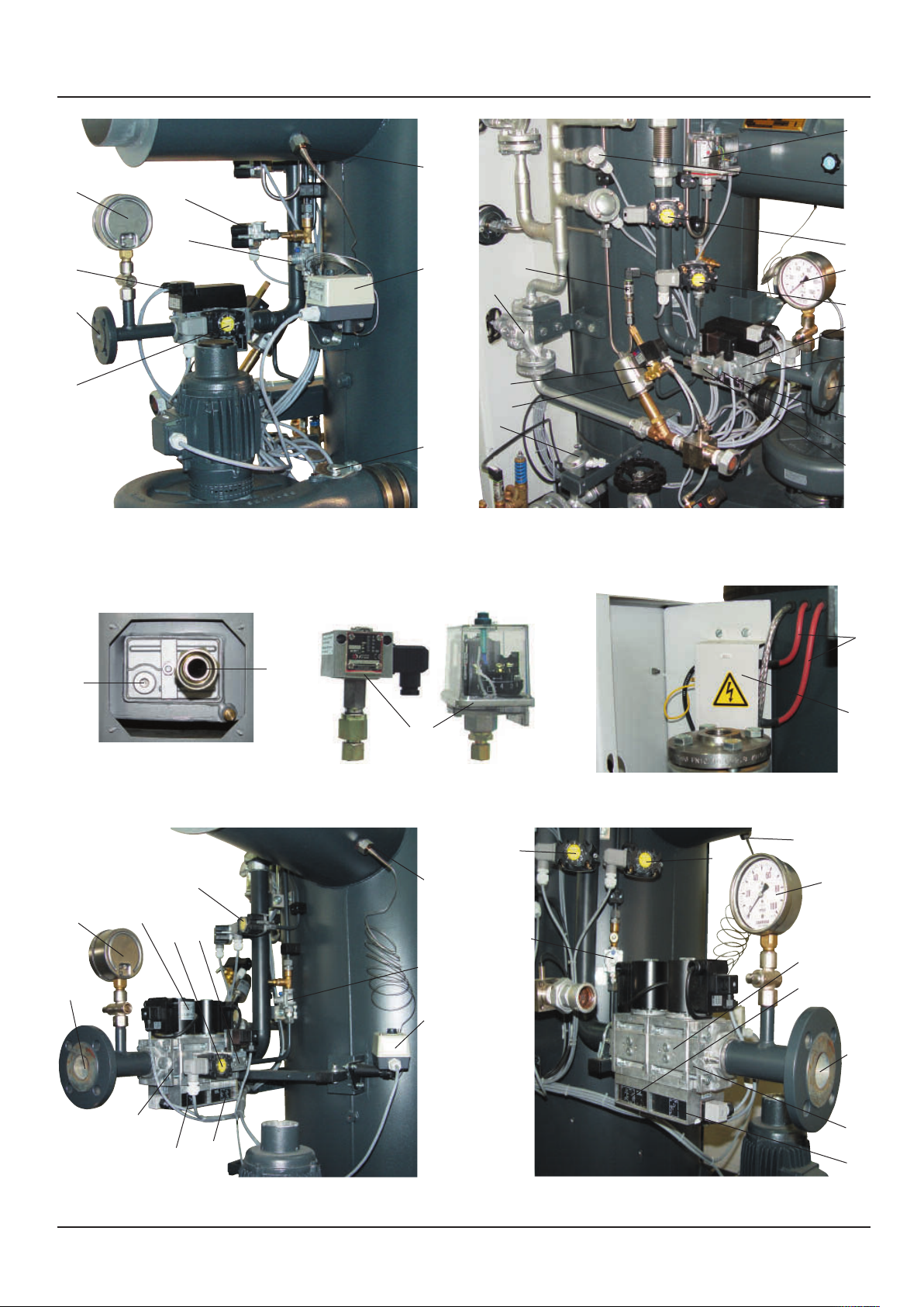
Übersicht Survey
Junior 80 – 200 Gas
Junior 80 – 200 gas
Junior 80 – 200 Gas
Junior 80 – 200 gas
Junior 250 – 400 Gas
Junior 250 – 400 gas
Junior 250 – 400 Gas
Junior 250 – 400 gas
Wassereintritt ohne Abdeckblech
Water inlet without cover anel
52
53
Zündtrafo mit Abdeckung
Ignition transformer with cover
42
44
40
111
45
43
82
72
14
17
16
15
42
44
40
45
41
112
66
9
10
6
33
44
14
39
40
112
45
98
41
111
44 40
66
43
39
45
41
98
112
82
111
14
4
19
15
Druckbegrenzer, Alternativen
Pressure limiter, alternatives
Sonderausführung
Special model Standard
Standard
42
39
98

6
Übersicht Survey
Rauchgasrückführung ohne Isolierung
Flue gas return without insulation
Anfahrleitung
tart-up line
5
Dampfautomat mit Gasfeuerung
ohne Kunststoffdeckel
team generator with gas firing
without plastic cover
21
49
418
9
11
20
1
2
Junior 80 – 400
19
21
34
82
65
Dampfautomat mit Ölfeuerung
ohne Kunststoffdeckel
team generator with oil firing
without plastic cover
64
5
110
32
85
103
24
25
26
30
31
37
2
83
84
27
63
62
28
29
23
74
76
Zuleitung
Supply
line
85
chaltschrank mit teuerung
Control cabinet with control
system
89
59
36
14
3
20
16
11
15
19
9
4
42
39
111
40
Junior 250 – 400 Gas

7
Übersicht Survey
1 Touchscreen
2 Hauptschalter mit Unterspannungsauslöser
3
ückschlagventil Dampfaustritt (nur bei Ausrüstung Thermotimat)
4 Anfahrkolbenventil (nur bei Ausrüstung Thermotimat)
5 Optische Flammüberwachung
6 Zündkabel
7 Automatisches Abschlämmventil (optional)
8 Manometer mit Nadelventil (optional)
9 3-Wege Pilotventil
10 Fühler PT 100 Wassereintrittstemperatur
11 Dampfmanometer
13 Vordruckpumpe (optional) (80–200 mit Drosselblende)
14 Fühler auchgastemperaturbegrenzer
15 Dampfdruckbegrenzer
16 Fühler PT 100 Dampftemperaturbegrenzer
17 Drucksensor Dampfdruckregelung
18 ückschlagklappe Anfahrleitung (nur bei Ausrüstung Thermotimat)
19 Anfahrventil
20 Hauptdampfventil
21 Sicherheitsventil
23 Feuerungsautomat
24 Motorschutzschalter Speisepumpe
25 Motorschutzschalter Gebläse
26 Motorschutzschalter Vordruckpumpe (optional)
27 Schmaleinbaurelais 230 V
28 Koppelrelais 24 V
29 Schmaleinbaurelais 24 V
30 Motorschütz Gebläse
31 Motorschütz Vordruckpumpe (optional)
32 Leitungsschutzschalter
33 Zündtransformator mit Abdeckung
34 auchgasrückführung (optional)
36 Gebläse Brenner
37 Motorschütz Wasserpumpe
39 Luftdruckwächter
40 Hauptgasventile Gaskompakteinheit (a + b)
41 Gasdruckwächter min. (Gaskompakteinheit)
42 Gasdruckwächter max.
43 Gasdruckwächter Dichtheitskontrolle
44 Gasmanometer mit Druckknopfventil
45 Gasanschluss
46 Brenner
47 Stauscheibe
49 auchgasanschluss
50 Heizschlange
51 Verdampferteil
52 Wassereintritt
53 einigungsstopfen
54 Wasserpumpe mit Motor
55 Wasserpumpendruckanschluss
56 ückschlagventil Wassereintritt
57 Abschlämmventil
58 Speisewasseranschluss
59 outer für Fernüberwachung (optional)
60 Ionisationselektrode Hauptflamme
61 Heißwasserfilter
62 Basismodul Easy 819
63 Easy 822 mit Erweiterung
64 Teillastbrenner
65 Ölpumpe
66 Gasventil Teillastbrenner
68 ohr Teillastbrenner
69 Ionisationselektrode Teillastbrenner
70 Magnetventil Luftdruckwächter
72 Luftstellklappe
73 Typenschild Dampfautomat
74 Klemmleiste
75 Wasservordrucksensor
76 Potentialverteiler
77 Wasserpumpenvordruck-Überströmventil
78 Speisewasserbehälter
79 Ölbrennerdüse
81 Probeentnahmeventil
82 auchgastemperaturbegrenzer
83 Dampftemperaturbegrenzer
84 Steuertrafo
85 Lüfter für Schaltschrank
86 Dampftrockner
87 Absperrventil
88 Kondensatableiter mit Schmutzfänger
89 auchgastemperaturbegrenzer elektronisch (optional)
92 Ölmagnetventil
93 Ölleitungsanschluss
95 Zündelektrode
98 Gasfilter (Gaskompakteinheit)
103 Motorschutzschalter Steuertrafo
107 Manometerprüfhahn (optional)
108 ückschlagventil Dampftrockner (nur bei Mehrfachanlagen)
109 Schauglas Dampftrockner
110 UV-Zelle Flammenüberwachung
111 Gasdruckregler Teillastbrenner
112 Gasdruckregler Hauptbrenner (Gaskompakteinheit)
1 Touch screen
2 Main switch with undervoltage release
3 eturn valve steam outlet (only for Thermotimat equipment)
4 Start-up piston valve (only for Thermotimat equipment)
5 Optical flame control
6 Ignition cable
7 Automatic blowdown valve (optional)
8 Manometer with needle valve (optional)
9 3-way pilot valve
10 Sensor PT 100 water inlet temperature
11 Steam pressure gauge
13 Pre-pressure pump (optional) (80-200 with restricting orifice)
14 Sensor flue-gas temperature limiter
15 Steam pressure limiter
16 Sensor PT 100 steam temperature limiter
17 Pressure sensor steam pressure controlling
18 Check valve start-up piping (only for Thermotimat equipment)
19 Start-up valve
20 Main steam valve
21 Safety valve
23 Firing control automat
24 Motor circuit breaker feed pump
25 Motor protection switch fan
26 Motor circuit breaker admission pressure pump (optional)
27 Narrow built-in relay 230 V
28 Coupling relay 24 V
29 Narrow built-in relay 24 V
30 Motor contactor fan
31 Motor contactor pre-pressure pump (optional)
32 Miniature circuit-breaker
33 Ignition transformer with cover
34 Flue gas return (optional)
36 Fan main burner
37 Motor contractor water pump
39 Air pressure controller
40 Main gas valves (gas compact unit)
41 Gas pressure controller min. (gas compact unit)
42 Gas pressure controller max.
43 Gas pressure detector leak monitoring
44 Gas pressure gauge with push button valve
45 Gas connection
46 Burner
47 Baffle plate
49 Flue gas connection
50 Heating coil
51 Evaporator
52 Water inlet
53 Cleaning plug
54 Water pump with motor
55 Water pump pressure connection
56 eturn outlet water inlet
57 Drain valve
58 Feed water connection
59 outer for remote monitoring (optional)
60 Ionisation electrode main flame
61 Hot water filter
62 Basic module Easy 819
63 Easy 822 with extension
64 Part-load burner
65 Oil pump
66 Gas valve part-load burner
68 Tube part-load burner (page 6)
69 Ionisation electrode part-load burner (page 6)
70 Solenoid valve air pressure detector
72 Adjustable air flap with servomotor
73 Type plate steam generator
74 Terminal strip
75 Water admission pressure sensor
76 Potential distributor
77 Water pump pre-pressure-overflow valve
78 Feed water tank
79 Oil burner injector
81 Sampling valve
82 Flue-gas temperature limiter
83 Steam temperature limiter
84 Control transformer
85 Fan for switch cabinet
86 Steam drier
87 Shut-off valve
88 Steam trap with dirt trap
89 Flue gas temperature limiter electronic (optional)
92 Solenoid valve oil
93 Oil connection
95 Ignition electrode
98 Gas filter (gas compact unit)
103 Motor protection switch control transformer
107 Manometer test cock (optional)
108 eturn valve steam dryer (only at multiple systems)
109 Inspection glass steam dryer
110 UV cell flame detector
111 Gas pressure regulator partial load burner
112 Gas pressure regulator main burner (gas compact unit)

8
Übersicht Survey
Gebläse Brenner
Fan main burner
Wasser um e installiert mit Wasser um endruckanschluss
Water um installed with water um ressure connection
Brenner Gas Junior 80 – 400
Burner gas Junior 80 – 400
Brenner Öl
Burner oil
Einstellung Zündelektroden
Adjustment ignition electrodes
Magnetventil Luftdruckwächter
Solenoid valve air ressure detector
55
56
58 58
54
75
77
10
57
79
95
95
79
47
46
80
15
2 4
69
60
68
46
64
8
Funktionsschema
Functional diagram
82
72
36
Wasserpumpe installiert mit Vordruckpumpe (Aufbaubeispiel)
Water pump installed with pre-pressure pump (exemplification)
61
9
7
58 87 13
8
54
75
77
56
10
55
57
81
95
95
65
92
87
93
21 11 15 17
20
3108
86
16
87
57
9
19
88
13
61
54
75
77
56
10
87
8
18
107
87
78
4
72
14
36
49
57
51
46
50
7
9
Y
Y
39
81
81
109
34
9
ACHTUNG!
Für die Sicherheit und einwandfreie Funktion die rot
hervorgehobenen Vorschriften und Hinweise in dieser
Betriebsanleitung besonders beachten.
Bei Nichtbeachtung entfallen alle Haftungs- und/oder
Gewährleistungsansprüche gegen den Hersteller.
1.1 Piktogramme
In dieser Betriebsanleitung werden folgende
Pikto gramme verwendet:
Dieses Piktogramm macht auf gefährliche
Situationen mit möglichen Personen- oder
Maschinenschäden aufmerksam.
Dieses Piktogramm macht auf gefährliche
Situationen durch elektrischen Strom aufmerk -
sam. Die auszuführenden Arbeiten dürfen nur
von einer lektrofachkraft ausgeführt werden.
Dieses Piktogramm macht auf Gefahren durch
heiße Oberflächen aufmerksam.
Dieses Piktogramm macht auf nützliche
Ratschläge, rläuterungen und rgänzungen
zur Handhabung des Dampfautomaten
aufmerksam.
1.2 Bestimmungsgemäße Verwendung
Der Dampfautomat ist gebaut nach dem Stand der
Technik und den anerkannten sicherheitstechnischen
Regeln. Dennoch können bei unsachgemäßer Verwen -
dung Gefahren für Leib und Leben des Benutzers oder
Dritter sowie Beeinträchtigungen des Dampfautomaten
und anderer Sachwerte entstehen.
Der Dampfautomat ist ausschließlich zur rzeugung von
Dampf bestimmt. ine andere oder darüber hinaus-
gehende Benutzung gilt als nicht bestimmungsgemäß.
Zur bestimmungsgemäßen Verwendung gehört auch,
dass der Bediener des Dampfautomaten die Betriebs -
anleitung vollständig gelesen und verstanden hat und
die in der Betriebsanleitung beschriebenen Betriebs -
bedingungen/Vorgehens weisen beachtet werden.
Der Dampfautomat darf nur mit den auf dem
Typenschild angegebenen Grenzwerten für Dampfdruck
und Beheizungsleistung sowie dem angegebenen
Brennstoff betrieben werden.
1.2.1 Verwendbare Brennstoe
1. Heizöl L nach DIN 51603- L-1
2. Gase der 1. Gasfamilie
rdgas L und H
3. Gase der 3. Gasfamilie
Propan und Butan
4. Gase der 4. Gasfamilie
Flüssiggas und rdgas-Luft-Gemische
Bei anderen Brennstoffen Kesselhersteller befragen.
ATTENTION
To assure safety and proper function, particularly pay
attention to the instructions and advices marked in red.
In case of non-compliance, all liability and warranty
claims against the manufacturer will become void.
1.1 Pictograms
In these operating instructions, the following pictograms
are used:
This pictogram points out dangerous situations
with possible bodily injuries or machinery
breakdowns.
This pictogram points out dangerous situations
caused by electric current. The corresponding
works shall be effected only by a specialised
electrician.
This pictogram points out dangers caused by
hot surfaces.
This pictogram points out useful advice,
explanations and additional notes concerning
operation of the steam generator.
1.2 Appropriate use
The steam generator is constructed according to the
state-of-the-art of technology and the approved safety
regulations. However, dangers for life and physical
condition of the operator or third parties as well as
impairments of the steam generator or other material
assets may be the result of inappropriate use.
The steam generator is designed only for the generation
of steam. Another or ultra vires use is not deemed to be
appropriate.
Appropriate use also implies that the operator of the
steam generator has read and understood the operation
instruction thoroughly and completely, and that the
operation conditions/processes described in the
operating instructions are adhered to.
The steam generator shall be run only with the limit
values for steam pressure and heating capacity indicated
on the type plate and with the indicated fuel as well.
1.2.1 Suitable fuels
1. Fuel oil L according to DIN 51603- L-1
2. Gases of the 1st gas family
natural gas L and H
3. Gases of the 3rd gas family
propane und butane
4. Gases of the 4th gas family
liquid gas and natural gas-air mixtures
For other fuels, please consult the manufacturer.
1 Allgemeines 1 General notes

10
1.3 Allgemeine Vorschriften
1.3.1 Bundesrepublik Deutschland
Der Dampfautomat ist nach der Richtlinie 2014/68/ U
des uropäischen Parlaments und des Rates vom 15. Mai
2014 hergestellt und ausgerüstet und hat ein C -
Kennzeichen.
Die erforderlichen Konformitätserklärungen werden für
jeden Dampfautomaten ausgestellt.
Nachstehende Normen und Vorschriften sind
berücksichtigt:
1. TRD, AD2000 und Teile der DIN N 12952.
2. DIN N 267, DIN N 676
Alle weiteren Normen nach DIN- N, DIN-ISO, DIN-
VD sowie VdTÜV-Werkstoffblätter und
VdTÜV-Merkblätter und Vereinbarungen.
3. Betriebssicherheitsverordnung – BetrSichV vom
01. Juni 2015 und Technische Richtlinien für
Betriebssicherheit-TRBS
4. Technische Anschlussbedingungen (TAB)
Gasversorger
5. Technische Anschlussbedingungen (TAB)
lektroversorger
6. Technische Anschlussbedingungen (TAB)
Wasserversorger
7. Bundes-Immissionsschutzgesetz sowie Länder-
Durchführungsverordnungen
8. Länder-Bauaufsichtsvorschriften
9. Berufsgenossenschaftliche Vorschriften
10. Im Übrigen gemäß den Regeln der Technik
1.3.2 Andere EU-Mitgliedsstaaten
Für die Aufstellung und den Betrieb sind die nationalen
Vorschriften der Mitgliedsländer zu beachten.
1.3.3 Länder außerhalb der EU
C RTUSS Dampfautomaten sind in vielen Ländern
außerhalb der U besonders zugelassen. Für die
Aufstellung und den Betrieb gelten die nationalen
Vorschriften.
Sicherheitstechnische Prüfungen jährlich und
wiederkehrend je nach nationalen Vorschriften
durch zugelassene Überwachungsstelle oder
durch einen autorisierten Kundendienst
veranlassen.
1.3 General Regulations
1.3.1 Federal Republic of Germany
The steam generator is manufactured and equipped
according to Directive 2014/68/ U of the uropean
Parliament and Council of 15th of May 2014 and has a
C mark.
The required Declarations of Conformity are issued for
each steam generator.
The following standards and regulations are taken into
account:
1. TRD, AD2000 and parts of DIN N 12952.
2. DIN N 267, DIN N 676
All further standards according to DIN- N, DIN-ISO,
DIN-VD , VdTÜV material data sheets and VdTÜV
technical bulletins and agreements.
3. Ordinance on Industrial Safety and Health –
BetrSichV of June 01, 2015 and Technical
Regulations on Industrial Safety and Health – TRBS
4. Technical connection requirements (TAB) gas
supplier
5. Technical connection requirements (TAB) power
supplier
6. Technical connection requirements (TAB) water
supplier
7. Federal Immission Protection Law and Federal State
proceeding regulations.
8. Federal state building inspection regulations
9. Regulations of the mployer´s Liability Insurance
Association.
10. In general, all regulations of technology are applied
1.3.2 Other EU members
For installation and operation, the national regulations
of the Member States have to be observed.
1.3.3 Non-EU members
C RTUSS steam generators are specially authorised in
many countries outside of the U. For installation and
operation, the national regulations are applied.
Have safety-specific inspections carried out
annually and recurrently in accordance with
national regulations by approved inspection
agency or by an authorized customer service.
1 Allgemeines 1 General notes
11
2.1 Anforderungen an Personen
Unfallgefahr!
Arbeiten am Dampfautomaten dürfen nur von
Personen ausgeführt werden, die aufgrund ihrer
Ausbildung und Qualifikation dazu berechtigt
sind. Außerdem müssen die Personen vom
Betreiber dazu beauftragt sein.
Anschluss-, Instandhaltungs- und Reparaturarbeiten
dürfen nur von ausgebildetem Fachpersonal
durchgeführt werden.
Personen, die am Dampfautomaten tätig sind, haben
darauf zu achten, dass sie weder sich noch andere durch
ihre Tätigkeit gefährden.
2.2 Pflichten des Betreibers
Unfallgefahr!
Von dem Dampfautomaten gehen Gefahren
aus, wenn er unsachgemäß oder nicht in
ordnungsgemäßem Zustand betrieben wird.
Der Betreiber ist verpflichtet, den Dampf auto maten nur
in einwandfreiem Zustand zu betreiben. Gefahrenstellen,
die zwischen dem Dampfautomaten und kundenseitigen
inrichtungen entstehen, müssen vom Betreiber
gesichert werden.
2.3 In der Bundesrepublik Deutschland
Gemäß Betriebssicherheitsverordnung – BetrSichV § 3 –
ist eine Gefährdungsbeurteilung der durch die
Benutzung der Dampfanlage und durch die
Arbeitsumgebung hervorgerufenen Gefahren
erforderlich.
2.4 Einteilung nach DGRL 2014/68/EU in
Gefahrenklassen
s sind auch andere max. zulässige Betriebs-
überdrücke zwischen 8 und 32 bar möglich.
2.1 Sta requirements
Risk of accident!
Operations on the steam generator shall only be
effected by persons who are authorised for it
because of their training and qualification.
Furthermore, the persons have to be instructed
for these operations by the operator.
Connection, maintenance and repair workings shall only
be effected by qualified and trained specialists.
Persons working on the steam generator must take care
not to endanger themselves or others by their activity.
2.2 Obligations of the operator
Risk of accident!
The steam generator may cause danger when
operated improperly or in improper condition.
The operator is obligated to use the steam generator
only in perfect condition. Danger zones arising between
the generator and the customer´s equipment have to be
protected by the operator.
2.3 In the Federal Republic of Germany
In accordance with the Ordinance on Industrial Safety
and Health BetrSichV § 3, a danger judgement for the
dangers which may result from the use of the steam
plant and from the work stations is required.
2.4 Classification in danger classes according to
PEO 2014/68/EU
Other maximum permissible operating
pressures between 8 and 32 bars possible.
2 Sicherheit 2 Safety
Typ C RTUSS Heizfläche
m2
Druck
bar
Inhalt
ltr.
Produkt
PS x V
Kategorie
Junior
80 – 120 3,1
10
16
25
32
9,5
95
152
237,5
304
II
III
Junior
150 – 200 5,3
10
16
25
32
21,1
211
337,6
527,5
675,2
III
Junior
250 – 400 7,7
10
16
25
32
32,3
323
516,8
807,5
1033,6
III
Type C RTUSS heating
surface
m2
pressure
bar
content
ltr.
product
PS x V
category
Junior
80 – 120 3,1
10
16
25
32
9,5
95
152
237,5
304
II
III
Junior
150 – 200 5,3
10
16
25
32
21,1
211
337,6
527,5
675,2
III
Junior
250 – 400 7,7
10
16
25
32
32,3
323
516,8
807,5
1033,6
III
12
2.5 Verantwortliche Personen bestimmen und
einweisen
Nur geschultes oder unterwiesenes Personal einsetzen.
Zuständigkeiten des Personals für das Bedienen, War ten,
Instandsetzen klar festlegen.
Regelmäßig das sicherheits- und gefahrenbewusste
Arbeiten des Personals unter Beachtung der Betriebs -
anleitung kontrollieren.
Das mit Tätigkeiten am Dampfautomaten beauftragte
Per sonal muss vor Arbeitsbeginn die Betriebsanleitung,
und hier besonders das Kapitel „Sicherheits maß -
nahmen“, sowie geltende Vorschriften gelesen und
verstanden haben.
Die Betriebsanleitung und geltende Vorschriften so
aufbewahren, dass sie dem Bedien- und Wartungs -
personal zugänglich sind.
rgänzend zur Betriebsanleitung
allgemeingültige gesetzliche und sonstige
verbindliche Rege lungen zur Unfallverhütung
und zum Umwelt schutz beachten und
anweisen!
2.6 Elektrische/elektronische Einrichtungen
Beim Kontakt mit unter Spannung stehenden Leitungen
oder Bauteilen besteht Lebensgefahr!
Vor Arbeiten an elektrischen/elektronischen inrich tun -
gen muss der Dampfautomat vom Netz getrennt
werden.
Den Dampfautomaten regelmäßig überprüfen.
Fest gestell te Mängel oder Störungen sofort beheben.
Den Dampfautomaten bis zum Beheben der Mängel
abschalten.
Sind Arbeiten an spannungsführenden Teilen
notwendig, eine zweite Person hinzuziehen, die im
Notfall die Span nungsversorgung ausschaltet. Den
Arbeitsbereich ab sperren und mit einem Warnschild
versehen. Nur spannungsisoliertes Werkzeug benutzen.
Sicherungen nicht reparieren oder überbrücken. Nur die
vom Hersteller vorgesehenen Sicherungen einsetzen.
Im Schaltschrank der elektrischen Steuerung des
Dampfautomaten keine externen
Zusatzsteuerungen oder Abgriffe anschließen!
s sind nur original C RTUSS-Zusatzeinrich -
tungen zugelassen.
Bei Fremdinstallationen erlöschen Kessel -
zulassung und Garantie!
2.5 Determine and instruct persons in charge
Only employ a trained or instructed staff. Determine
clearly the responsibilities of the staff for operation,
maintenance, repairing.
Check regularly if the staff work safety-conscious and
danger-aware in compliance with the operating
instructions.
The staff charged with operations on the steam
generator has to have read and understood the
operating instruction – and here in particular the chapter
“safety measures” as well as the applicable regulations
before starting work.
Keep operating instructions and applicable regulations
available for the service and maintenance staff.
In addition to the operating instructions,
observe and advice general legal and other
binding regulations related to accident
prevention and environmental protection.
2.6 Electrical/Electronic equipment
There is danger of life when contacting live wires or
construction elements!
Before working on electrical/electronical equipment, the
steam generator has to be disconnected from the power
supply.
Check the steam generator regularly. liminate detected
defects or faults immediately. Shut off the steam
generator until the defects are eliminated.
If operations on live parts are necessary, call in a second
person who can switch off the power supply in case of
emergency. Close off the working area and install a
danger sign. Use only tools which are insulated against
voltage.
Do not repair or bridge fuses. Use only the fuses
intended to be inserted by the manufacturer.
Do not connect any external supplementary
control systems or taps in the control cabinet of
the electrical control system of the steam
generator!
Only original C RTUSS supplementary devices
are approved and permitted.
In the case of external installations the boiler
approval and guarantee become invalid!
2 Sicherheit 2 Safety

13
2.7 Sicherheit bei Wartungsarbeiten
Arbeiten an elektrischen Ausrüstungen dürfen
nur von einer lektrofachkraft oder von unter -
wiesenen Personen unter Leitung und Aufsicht
einer lektrofachkraft gemäß den elektrotech -
nischen Regeln vorgenommen werden.
Arbeiten an gastechnischen Ausrüstungen
dürfen nur von hierfür ausgebildetem Personal
mit speziellen Kenntnissen und rfahrungen in
diesem Bereich vorgenommen werden.
Den Dampfautomaten gemäß dieser Betriebsanleitung
ausschalten und gegen Wiedereinschalten sichern.
Am Dampfautomaten ein Warnschild anbringen.
Den Instandsetzungsbereich weiträumig absichern.
Schutzhauben und Abdeckungen nach Beendigung der
Wartungsarbeiten wieder aufsetzen.
Verbrühungsgefahr!
Bei Arbeiten an der Wasserpumpe den Wasser -
zulauf absperren.
Nur bei druckloser Kesselanlage Arbeiten an
Armaturen und Rohrleitungssystemen
vornehmen.
Vorsicht bei Reparaturen an heißen Rohr leitun -
gen und Armaturen.
Verätzungsgefahr!
Bei der Verwendung von Reinigungs- und
Kes selsteinlösungsmittel Schutzkleidung tragen.
Anwendungsvorschriften der Hersteller
beachten!
Verplombte Sicherheitseinrichtungen aller Art
dürfen nur durch den autorisierten Kunden -
dienst geöffnet und verstellt werden. Danach
müssen die Sicherheitseinrichtungen wieder
verplombt werden.
2.8 Ersatzteile
rsatzteile müssen den vom Hersteller des Dampf -
automaten festgelegten technischen Anforderungen
entsprechen. Dies ist bei Originalersatzteilen immer
gewährleistet.
2.9 Wiederverwertung und Entsorgung von
Schmier- und Problem stoen
Nicht mehr verwendete Problemstoffe, wie Schmier stoffe
oder Öl, gehören nicht in den Müll oder in das Abwasser.
Nicht mehr verwendbare Stoffe, elektronische Bauteile
sowie Batterien bei den dafür vorgesehenen
ntsorgungs stellen abgeben.
Vor einer Demontage zur Wiederverwertung oder
Ver schrottung Öle und andere wassergefährdende Stoffe
restlos entfernen.
2.7 Safety during maintenance operations
Operations on electrical equipment shall only be
effected by a specialised electrician or by
instructed persons under direction and super -
vision of a specialised electrician in accordance
with the regulations of electrical engineering.
Operations on gas equipment shall only be
effected by a specially trained staff with special
knowledge and experience in this field.
Switch off steam generator according to these operation
instructions and protect against restart.
Install a danger sign onto the steam generator.
Protect a spacious area around the repairing zone.
Replace all protection caps and covers when
maintenance workings are completed.
Danger of scalding!
Shut-off water supply during operations on the
water pump.
Only effect operations on fittings and piping
systems when the steam generator installation
is pressure-free.
Be cautious when repairing hot pipings or
fittings.
Danger of causticization!
Wear protective clothes when using cleaning
and scale deposit solvents.
Pay attention to the application instructions of
the manufacturer!
All kinds of sealed safety devices shall only be
opened and adjusted by an authorised service
technician. Afterwards, they have to be sealed
again.
2.8 Spare parts
Spare parts must comply with the technical requirements
determined by the manufacturer of the steam generator.
This is always guaranteed for original spare parts.
2.9 Recycling and disposal of lubricating and
harmful substances
Problematic substances such as lubricants or oil which
are not used any longer, do not belong to waste or
sewage. Dispose of substances that can no longer be
used, electronic components as well as batteries at the
appropriate provided disposal facilities.
Before dismantling for recycling or scrapping, remove all
oils and other water polluting substances.
2 Sicherheit 2 Safety
14
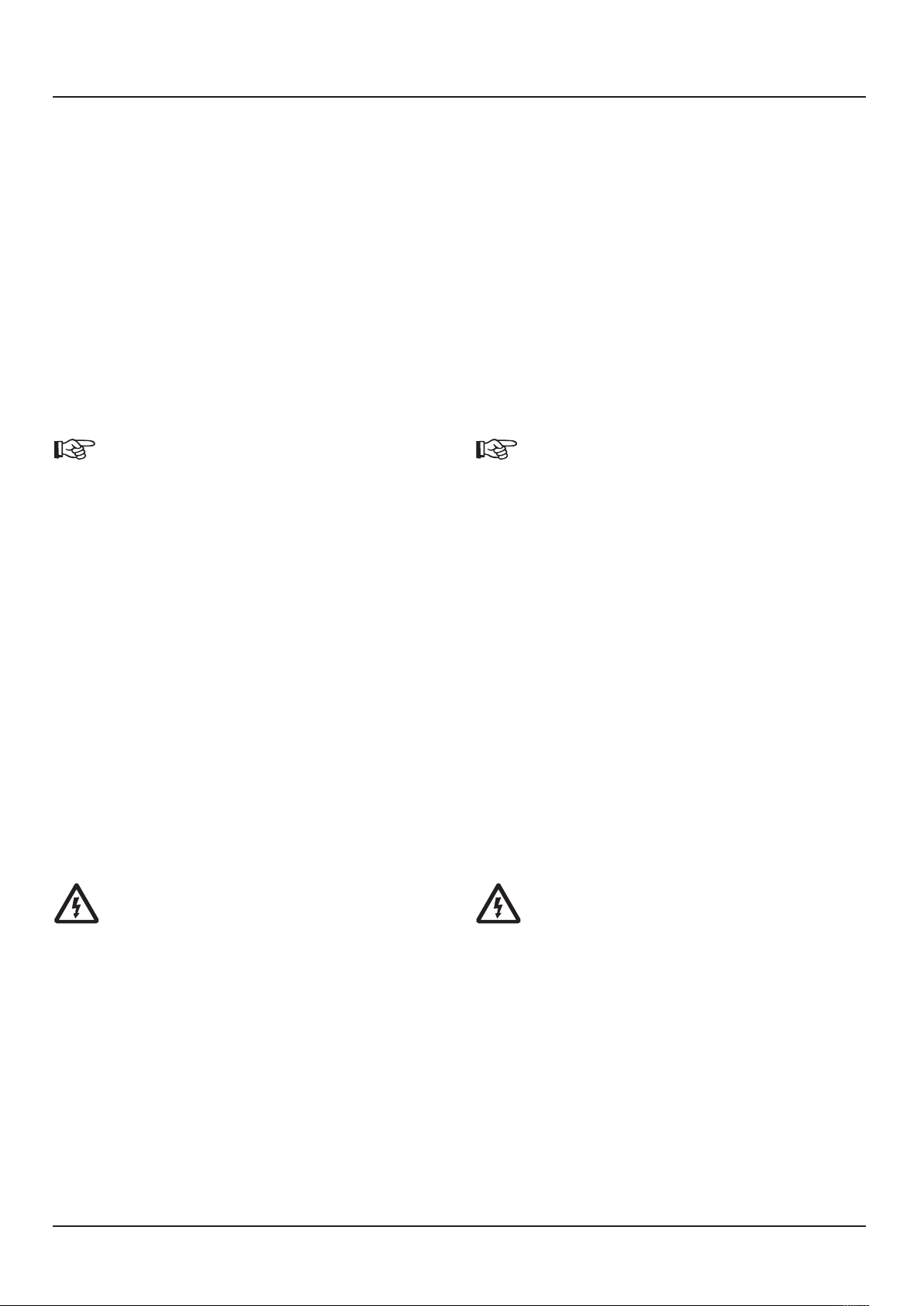
2.10 Mögliche elektrische Netzversorgungen
2.10.1 In der Standardausführung der Dampf auto -
maten ist die lektroversorgung für 3/N/P ~ 50
Hz 230V/400V ± 10% ausgelegt entsprechend
TN-C-S-System.
Auch an TN-C-, TN-S-, TT- und IT-Systemen kann
ohne Zusatzausrüstung angeschlossen werden.
2.10.2 Abweichende lektroversorgungen bedürfen
der Abstimmung mit dem Hersteller.
2.10.3 Netzversorgungsbeispiele
Bei von der Standardaus rüstung abweichenden
Netzanschlüssen, Spannungen oder Frequenzen
prüfen, ob der Dampfautomat entsprechend
ausgerüstet ist.
lektrische Bauteile können beschädigt werden!
2.10 Selection of electrical power supply
2.10.1 The steam generator standard version is
designed for an electrical power supply of
3/N/P ~ 50 Hz 230V/400V ± 10%
according to TN-C-S-system.
Can also be connected to TN-C, TN-S, TT and IT
systems without supplementary equipment.
2.10.2 Different kinds of power supply have to be
agreed with the manufacturer.
2.10.3 xamples for power supply
When power connections, voltages or
frequencies are different from the standard
version, check if the steam generator is
equipped correspondingly.
lectrical elements may be damaged!
2 Sicherheit 2 Safety

15
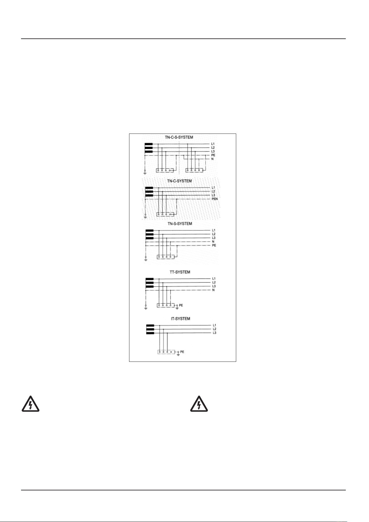
3.1 Funktionsbeschreibung Dampfautomat
Zum Start des Dampfautomaten mit Ausrüstung
Thermotimat sind das Haupt dampfven til (20), das
Anfahrventil (19) und das Abschlämmventil (57)
geöffnet. Nach Auslösen des Startvorgangs am Touch -
screen (1) füllt die Wasserpumpe (54) das Heizsystem
auf.
Gleichzeitig wird durch das Gebläse (36) die
Verbrennungsluft über die Absaugöffnungen im oberen
Deckel des Dampfautomaten, den äußeren Saugmantel
und den Gebläsekasten angesaugt.
Über die Druckseite des Gebläses wird die
Verbrennungsluft durch den inneren
Luftführungsmantel dem Brenner zugeführt.
Nach Befüllung des Heizsystems wird der Hauptbrenner
aktiviert.
Die sich jetzt erwärmenden inneren Mäntel sorgen für
eine schnelle Vorwärmung der Verbrennungsluft im
inneren Luftführungsmantel. Die ständig über den Saug -
mantel nachgeführte Luft verhindert die rwärmung des
äußeren Kesselmantels.
Die Rauchgase durchströmen das Verdampferteil (51)
und werden nach Umströmung der Heizschlange (50)
über den Rauchgasanschluss (49) in den Schornstein
geleitet.
Das während des Anfahrvorganges entstehende Wasser-
Dampfgemisch wird über das Anfahrventil (19) zum
Speisewasserbehälter (78) zurückgeführt.
Nach rreichen des Sattdampfzustandes mit einer
Temperatur von > 100°C wird das Anfahrkolbenventil (4)
geschlossen. Der Dampf automat ist jetzt in Betrieb.
Die Dampferzeugung wird durch den Drucksensor (17)
vollautomatisch geregelt und überwacht.
Im Touchscreen wird die jeweilige Dampfleistung
zwischen 0 – 100% angezeigt.
Bei Ausrüstung ohne Thermotimat-Vollautomatik
muss das Hauptdampfventil (20) und das
Abschlämmventil (57) geschlossen, das Anfahrventil (19)
geöffnet sein. Nach rreichen des Sattdampfzustandes
ist das Hauptdampfventil (20) langsam zu öffnen und
danach das Anfahrventil (19) langsam zu schließen.
3.1 Functional description of steam generator
The main steam valve (20), the start-up valve (19) and
the blowdown valve (57) are opened to start the steam
generator with Thermitomat equipment. After the start
process has been initiated at the touch screen (1) the
water pump (54) fills the heating system.
At the same time the fan (36) draws in the combustion
air through the suction openings in the top cover of the
steam generator, the outer suction shell and the blower
box.
Via the pressure end of the fan the combustion air is
blown through the inner air flow casing to the burner.
After the heating system has been filled, the main burner
is activated.
The inner shells are heating up now, providing a quick
pre-heating of the combustion air in the inner air duct
shell. The constant feeding of air over the suction shell
prevents a warming of the outer boiler shell.
The flue gases are streaming through the evaporator (51)
and, after having streamed around the heating coil (50),
they are led to the chimney over the flue gas connection
(49).
The water-steam mixture arising during the start-up
process is returned to the feed water tank (78) via the
start-up valve (19).
After the saturated steam state with a temperature >
100°C, the start-up piston valve (4) is closed. The steam
generator is now in operation.
Steam generation is controlled and monitored fully
automatically by the pressure sensor (17).
The respective steam output is indicated in the touch
screen between 0 – 100%.
At systems without Thermotimat full automatic
control system the main steam valve (20) and the
blowdown valve (57) have to be closed and the start-up
valve (19) opened. After the saturated steam state has
been reached, the main steam valve (20) has to be
opened slowly and then the start-up valve (19) closed
slowly.
3 Funktion 3 Function
16
3 Funktion 3 Function
3.2 Beschreibung der Gasfeuerung
Nachdem ein Hand- oder Automatikstart in der
Steuerung ausgelöst wurde, erfolgt eine Dichtheits -
kontrolle der Hauptgasventile (40a und 40b) durch den
Feuerungsautomaten in Verbindung mit dem Gasdruck -
wächter Dichtheitskontrolle (43). Parallel dazu wird das
Gebläse (36) in Betrieb gesetzt, die Speisewasserpumpe
wird gestartet. Der Luftdruck wächter (39) überwacht
den Luftdruck vor der Brenner mischeinrichtung und die
Luftvorspülzeit beginnt.
Anschließend öffnet das Gasventil Teillastbrenner (66)
sowie das Gassicherheitsventil (40a) und die
Teillastflamme wird gezündet. Die Flamm bildung wird
durch eine Ionisationselektrode in Ver bin dung mit einer
Flamm überwachung im Feuerungs automat kontrolliert.
Bei ausreichender Befüllung des Drucksystems mit
Kesselspeisewasser, ermittelt über den Differenzdruck
zwischen Wasservordrucksensor (75) und Drucksensor
Dampfdruckregler (17), öffnen nach Ablauf der
Mindestbefüllzeit das Gasventil (40b) mit integriertem
Gasdruckregler und der Hauptbrenner (46) wird mit Gas
beaufschlagt und dann durch die Teillast flamme
gezündet. Die Überwachung der Hauptflamme wird nun
durch die Ionisationselektrode Hauptflamme (60)
übernommen. Der Dampfautomat ist jetzt in Betrieb mit
einer Brennerleistung von 100%.
Über den Drucksensor Dampfdruckregelung (17) und der
elektronischen Steuerung wird der tatsächliche
Dampfdruck erfasst.
Bei steigendem Dampfdruck wird dann der Brenner und
die Speisepumpe voll abgeschaltet.
Bei sinkendem Dampfdruck erfolgt dann wieder der
Brenner- und Pumpenstart.
3.2 Description of gas firing
After a manual or automatic start has been initiated in
the control system, a leak check if the main gas valves
(40a and 40b) is carried out by the automatic furnace in
combination with the gas pressure detector leak
monitoring (43). At the same time the fan (36) is started
up and the feed water pump is started. The air pressure
detector (39) monitors the air pressure before the burner
mixing unit and the air purging time begins.
Subsequently the gas valve partial load burner (66) as
well as the gas safety valve (40a) open and the partial
load flame is ignited. Flame formation is monitored by an
ionization electrode in combination with a flame
monitoring unit in the automatic furnace.
When the pressure system is filled sufficiently with boiler
feed water, which is determined through the differential
pressure between the water pre-pressure sensor (75) and
the pressure sensor, steam pressure controller (17), the
gas valve (40b) with integrated gas pressure regulator
open after the minimum filling time has expired, and the
main burner (46) is pressurized with gas and then ignited
by the partial load flame. Monitoring of the main flame is
now taken over by the ionization electrode main flame
(60). The steam generator is now in operation with a
burner output of 100%.
The actual steam pressure is detected via pressure sensor
steam pressure controlling (17) and the electronic control
system.
When the steam pressure rises, the burner and the feed
pump are switched off completely.
When the steam pressure drops, the burner and pump
are started again.
Junior 80 – 200 Gas
Junior 80 – 200 gas
Junior 80 – 200 Gas
Junior 80 – 200 gas
41
66
44
39
42
17
40a + b
98
45
39 111
42
17
3 Funktion 3 Function
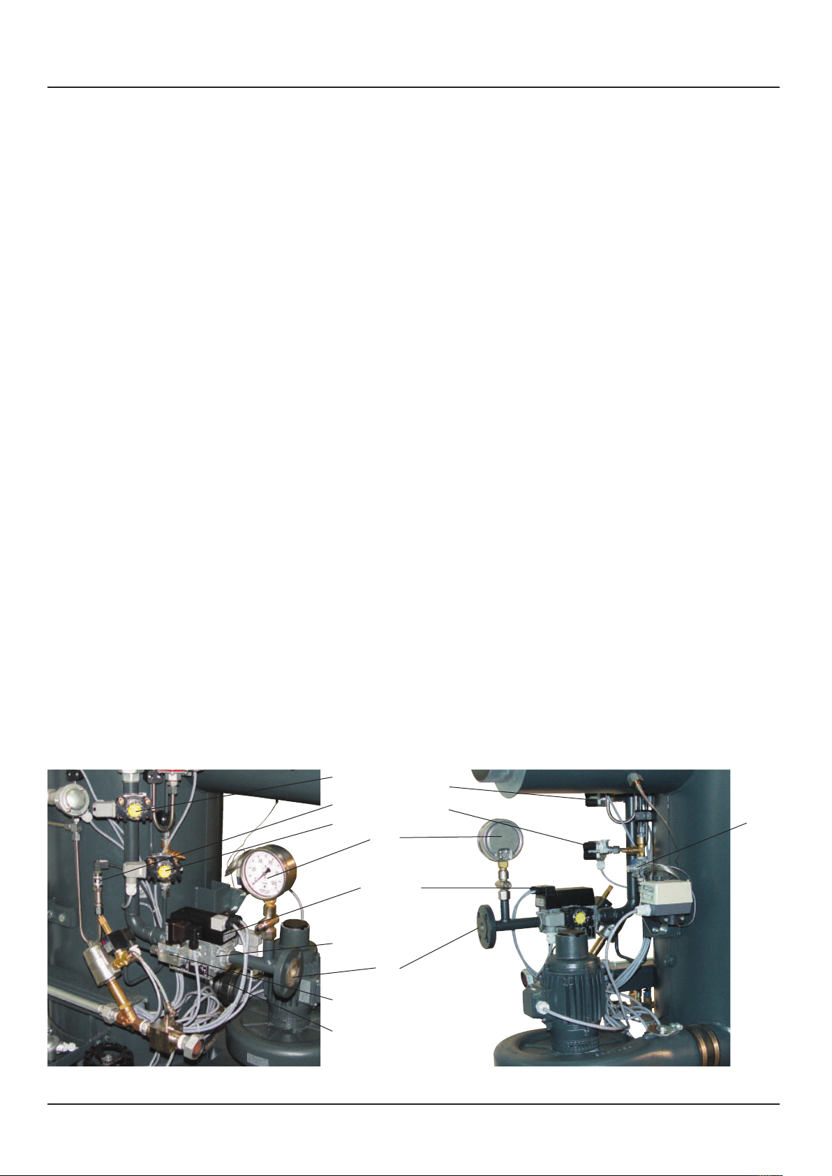
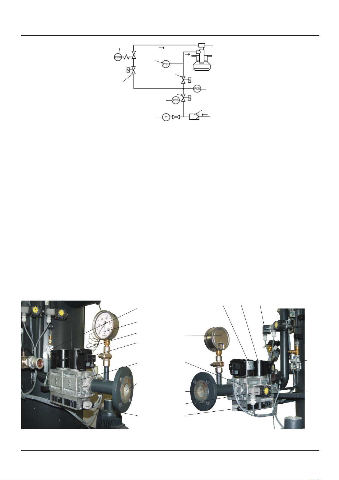
40a Gassicherheitsventil
40b Gasventil
41 Gasdruckwächter min.
42 Gasdruckwächter max.
43 Gasdruckwächter Dichtheitskontrolle
44 Gasmanometer mit Druckknopfventil
45 Gasanschluss
46 Brenner
64 Teillastbrenner
66 Gasventil Teillastbrenner
98 Gasfilter
111 Gasdruckregler Teillastbrenner
40a Gas safety valve
40b Gas valve
41 Gas pressure controller min.
42 Gas pressure controller max.
43 Gas pressure detector leak monitoring
44 Gas manometer with push button valve
45 Gas connection
46 Burner
64 Part-load burner
66 Gas valve part-load burner
98 Gas filter
111 Gas pressure regulator partial load burner
Funktionsschema Gasfeuerung
Functional diagram gas firing
Gasstrecke Junior 250 – 400
Gas system Junior 250 – 400
66
42
41
44
98
46
43
64
40b
40a
44
40a 40b 42 39
45
98
41
43
111
66
Junior 250 – 400 Gas
Junior 250 – 400 gas
45
98
44
40b
40a
42 39
111
111
45
41

18
3 Funktion 3 Function
3.3 Beschreibung der Gasfeuerung mit
Rauchgasrückführung
Der Funktionsablauf zum Starten des Dampfautomaten
und die Funktion des Gasbrenners sind entsprechend der
Beschreibung 3.2 der Gasfeuerung.
Der Dampfautomat hat jedoch zusätzlich ein
Rauchgasrückführungsrohr (34) vom Abgasstutzen bis
zur Saugseite des Verbrennungsluftgebläses (36).
Beim Betrieb der Brennereinrichtung wird immer der
Verbrennungsluft für den Hauptbrenner (46) ein Teil des
Rauchgases durch Zuführung auf die Ansaugseite des
Gebläses (36) beigemischt.
Dies senkt den Sauerstoffanteil in der Verbrennungsluft.
Die Flammentemperatur wird abgesenkt und es
entstehen weniger thermische Stickoxyde.
Die Verbrennungsluftmenge für den Brenner (46) wird
an der Luftklappe (72) entsprechend der Brennerleistung
fest eingestellt.
3.3 Description of the gas firing with
flue gas return
The function sequence for steam generator start and the
function of the gas burner in compliance with
description 3.2 of the gas firing.
However, the steam generator has an additional flue gas
return line (34) from the exhaust gas connection to the
suction side of the combustion air fan (36).
During operation of the burner device, a part of the flue
gas is always added to the combustion air for the main
burner (46) by supplying it to the suction side of the fan
(36).
This reduces the oxygen ratio in the combustion air.
The flame temperature is dropped and less thermal
nitrogen oxides are produced.
The combustion air quantity for the burner (46) is set
fixed at the air flap (72) in accordance with the burner
output.
Gebläse
Fan
92
72
36
Rauchgasrückführung ohne Isolierung
Flue gas return without insulation
34
36
65
17
39

19
3 Funktion 3 Function
3.4 Beschreibung der Ölfeuerung
Nachdem ein Hand- oder Automatikstart in der
Steuerung ausgelöst wurde, werden das Gebläse (36)
mit der integrierten Ölpumpe und die
Speisewasserpumpe in Betrieb gesetzt.
Bei ausreichender Befüllung des Drucksystems mit
Kesselspeisewasser wird über den Differenzdruck
zwischen Wasservordrucksensor (75) und Drucksensor
Dampfdruckregler (17), nach Ablauf der
Mindestbefüllzeit, die Feuerung freigegeben.
Der Luftdruckwächter (39) schaltet bei ausreichendem
Luftdruck frei.
Im Anschluß beginnt die Vorzündzeit, nach deren Ablauf
die Freigabe des Ölmagnetventils erfolgt. Das
eingesprühte Öl wird im Brenner gezündet und der
Brenner geht in Betrieb.
Die Flammbildung wird durch eine UV-Zelle (110) in
Verbindung mit der Flammüberwachung im
Feuerungsautomat kontrolliert.
Parallel dazu startet die Speisewasserpumpe. Über den
Drucksensor Dampfdruckregelung (17) und der
elektronischen Steuerung wird der tatsächliche
Dampfdruck erfasst.
Bei rreichen des vorgewählten Dampfdruckes schließt
das Ölmagnetventil (92) und die Speisepumpe schaltet
ab. Bei sinkendem Dampfdruck wird dann wieder
zugeschaltet bis zum rreichen des Regel -
abschaltpunktes.
3.5 Beschreibung der Ölfeuerung mit
Rauchgasrückführung
Der Funktionsablauf zum Starten des Dampfautomaten
und die Funktion des Ölbrenners sind entsprechend der
Beschreibung 3.4 der Ölfeuerung.
Der Dampfautomat hat jedoch zusätzlich ein
Rauchgasrückführungsrohr (34) vom Abgasstutzen bis
zur Saugseite des Verbrennungsluftgebläses (36).
Beim Betrieb der Brennereinrichtung wird nun der
Verbrennungsluft zur Senkung des Sauerstoffanteils ein
Teil des Rauchgases durch Zuführung auf die
Ansaugseite des Gebläses (36) beigemischt. Die
Flammentemperatur wird abgesenkt und es entstehen
weniger thermische Stickoxyde.
Die Verbrennungsluftmenge für den Brenner (46) wird
an der Luftklappe (72) entsprechend der Brennerleistung
fest eingestellt.
3.4 Description of oil firing
After a manual or automatic start has been initiated in
the control system, the fan (36) with the integrated oil
pump are started up and the feed water pump is started.
If the pressure system is filled sufficiently with boiler feed
water, the firing is enabled through the differential
pressure between the water pre-pressure sensor (75) and
the pressure sensor steam pressure controller (17) after
expiry of the minimum filling period.
The air pressure detector (39) is enabled when the air
pressure is sufficient.
First the pre-ignition time starts and after it has expired
the oil solenoid valve is enabled. The sprayed-in oil is
ignited in the burner and the burner starts operation.
Flame formation is monitored by a UV cell (110) in
combination with a flame monitoring function in the
automatic furnace.
The feed water pump starts in parallel. The actual steam
pressure is detected via pressure sensor steam pressure
controlling (17) and the electronic control system.
When the preselected steam pressure is reached, the oil
solenoid valve (92) closes and the feed pump switches
off. When the steam pressure drops the system cuts back
in until the controlled shut-down point is reached.
3.5 Description of the oil firing with
flue gas return
The function sequence for steam generator start and the
function of the oil burner are in compliance with
description 3.4 of the oil firing.
However, the steam generator has an additional flue gas
return line (34) from the exhaust gas connection to the
suction side of the combustion air fan (36).
During operation of the burner equipment, a part of the
flue gas is now added to the combustion air by feeding it
to the suction side of the fan (36) in order to reduce the
oxygen ratio. The flame temperature is dropped and less
thermal nitrogen oxides are produced.
The combustion air quantity for the burner (46) is set
fixed at the air flap (72) in accordance with the burner
output.
46 Brenner
65 Ölpumpe
92 Ölmagnetventil
93 Ölanschluss
46 Burner
65 Oil pump
92 Solenoid valve oil
93 Oil connection
Funktionsschema Ölbrenner
Functional diagram oil burner
46
92
65
93

20
3 Funktion 3 Function
3.6 Betrieb mit Zusatzausrüstung Thermotimat
Der C RTUSS Thermotimat ist eine integrierte,
elektronische Steuerung mit Schaltelementen als
Zusatzeinrichtung mit verschiedenen Optionen nur für
die C RTUSS Dampfautomaten.
r ermöglicht das vollautomatische Starten und
Abschalten eines Dampfautomaten sowie noch weitere
Funktionen, je nach Ausrüstung.
Wählbar sind zum Beispiel:
- Automatisches Ein- und Ausschalten zu fest
programmierten Zeitpunkten.
- Automatisches Ein- und Ausschalten durch
potentialfreie Kontakte von externen Auslösern wie
Bussystemen, Überwachungsgeräten oder
Dampfverbrauchern zu unterschiedlichen
Zeitpunkten.
- Jederzeitiges Ein- und Ausschalten von Hand durch
den Bediener am teuergerät.
- Abschlämmen des Dampfautomaten nach jedem
automatischen und handausgelösten Ausschalten.
- tartentwässerung bei jedem automatischen oder
handausgelösten tart des Dampfautomaten.
- Automatische Ein- und Ausschaltung eines Zusatz -
kessels bei Dampfnetzdruck unter schreitungs -
überwachung.
- Automatisches Einschalten eines Zusatzkessels bei
törabschaltung eines Grundlastkessels.
- Betrieb mit zwei unterschiedlichen Arbeitsdruck -
bereichen in bestimmten Zeitfenstern.
3.6.1 Integrierte Vollautomatik (Option)
1. Automatische Startentwässerung
Sie besteht aus einem pneumatisch betätigten
Anfahr-Kolbenventil (4) mit 3-Wege-Pilotventil (9),
das bei jedem Neustart des Dampf auto maten für
eine bestimmte Zeit öffnet. Darüber wird während
der Startphase das Anfahr wasser zum
Speisewasserbehälter zurück geführt, um
Wasserschläge zu vermeiden.
2. Automatische ntschlämmung
Sie besteht aus einem pneumatisch betätigten
Anfahr-Kolbenventil (4) mit 3-Wege-Pilotventil (9),
das bei jedem Abschalten des Dampf automaten für
eine bestimmte Zeit öffnet. Darüber erfolgt die
notwendige regelmäßige Abschlämmung des
Heizsystems.
Für ein vollautomatisches in- und Ausschalten
der C RTUSS Dampfautomaten sind je nach
Aufstellland zusätzliche Ausrüstungen in der
Dampfanlage vorgeschrieben.
In einigen Ländern gilt auch ein generelles
Verbot zum automatischen in- und
Ausschalten für alle Dampferzeuger oder ab
einer bestimmten Gefahrenklasse.
3.6 Operation with Thermotimat supplementary
equipment
The C RTUSS Thermotimat is an integrated electronic
control system with switching elements as a
supplementary device with various options only for the
C RTUSS steam generators.
It enables a fully automatical starting and stopping of a
steam generator as well as further functions, depending
on the equipment.
The following can, for example, be selected
- Automatic starting and stopping at fixed times.
- Automatic activation and deactivation through
potential-free contacts of external tripping units such
as bus systems, monitoring devices or steam
consumers at different moments.
- With the control device the operator can effect a
manual starting and stopping at any time.
- Blowdown of steam generator after every
automatical or manual switch-off.
- tart draining after every automatical or manual start
of the steam generator.
- Automatic starting and stopping of an additional
steam generator for units with steam network
underpressure control devices.
- Automatic connection of an additional steam gene ra -
tor when base load generator has a fault shutdown.
- Operation with two different operating pressure
ranges in specific time windows.
3.6.1 Integrated full automatic control system
(optional)
1. Automatic start dewatering
It consists of a pneumatically operated start-up
piston valve (4) with 3-way pilot valve (9) that
opens for a specific period at every restart of the
steam generator. In addition, the start-up water
is fed back to the feed water tank during the
starting phase in order to avoid water shocks.
2. Automatic desliming
It consists of a pneumatically operated start-up
piston valve (4) with 3-way pilot valve (9) that
opens for a specific period at every shutdown of
the steam generator. In addition, the required
regular blowdown of the heating system is
ensured.
For the fully automatic starting and stopping of
C RTUSS steam generators, national regulations
may require additional equipment for the steam
generating system.
In some countries it is generally forbidden to
start and stop automatically all steam
generators or those belonging to a certain
danger class.
This manual suits for next models
3
Table of contents
Other CERTUSS Iron manuals


