Cervis SmaRT BU-xH8D Series User manual

2019 Cervis, Inc.
SmaRT BU-xH8D
Base Unit Family
900MHz and 2.4GHz Manual
U088.4.4-SmaRT_BU-xH8D
™

SmaRT BU-xH8D Base Unit Family
FCC Statements
15.19 –Two Part Warning
This device complies with Part 15 of the FCC rules. Operation is subject to the following two conditions:
(1) This device may not cause harmful interference and
(2) This device must accept any interference received, including interference that may cause undesired operation.
15.21 –Unauthorized Modification
NOTICE: The manufacturer is not responsible for any unauthorized modifications to this equipment made by the user. Such modifications could
void the user’s authority to operate the equipment.
15.105(b) –Note:
Note: This equipment has been tested and found to comply with the limits for a Class B digital device, pursuant to part 15 of the FCC Rules.
These limits are designed to provide reasonable protection against harmful interference in a residential installation. The equipment generates,
uses and can radiate radio frequency energy and, if not installed and used in accordance with the instructions, may cause harmful interference to
radio communications. However, there is no guarantee that interference will not occur in a particular installation. If this equipment does cause
harmful interference to radio or television reception, which can be determined by turning the equipment off and on, the user is encouraged to try
to correct the interference by one or more of the following measures:
Reorient or relocate the receiving antenna.
Increase the separation between the equipment and receiver.
Connect the equipment into an outlet on a circuit different from that to which the receiver is connected.
Consult the dealer or an experienced radio/TV technician for help.
Industry Canada Statement
This device complies with Industry Canada licence-exempt RSS standard(s). Operation is subject to the following two conditions: (1) this device may not
cause interference, and (2) this device must accept any interference, including interference that may cause undesired operation of the device.
Le présent appareil est conforme aux CNR d'Industrie Canada applicables aux appareils radio exempts de licence. L'exploitation est autorisée aux deux
conditions suivantes : (1) l'appareil ne doit pas produire de brouillage, et (2) l'utilisateur de l'appareil doit accepter tout brouillage radioélectrique subi, même
si le brouillage est susceptible d'en compromettre le fonctionnement.
RoHS Compliance Statement
Cervis, Inc. complies with the requirements of Restriction of Hazardous Substances (RoHS/WEEE) Specification based on in-house practice and
declaration of compliance from our vendors. For additional information concerning RoHS compliance, please contact Cervis, Inc. at:
CERVIS, Inc.
170 Thorn Hill Road Warrendale, PA 15086 Phone: 724.741.9000 Fax: 724.741.9001
This product may contain material that may be hazardous to human health and the environment. In compliance with EU
Directive 2002/96/EC on Waste Electrical and Electronic Equipment (WEEE):
Do not dispose of the product as unsorted municipal waste.
This product should be recycled in accordance with local regulations. Contact local authorities for detailed
information.
This product may be returnable to the distributor for recycling. Contact your distributor for details.
Industry Canada Statement
This device complies with Canadian RSS-210.
The installer of this radio equipment must ensure that the antenna is located or pointed such that it does not emit RF field in excess of Health Canada limits
for the general population; consult Safety Code 6, obtainable from Health Canada’s website https://www.canada.ca/en/health-
canada/services/environmental-workplace-health/reports-publications/radiation/safety-code-6-health-canada-radiofrequency-exposure-guidelines-
environmental-workplace-health-health-canada.html.
Le présent appareil est conforme à la norme CNR-210 d'Industrie Canada.
L'installateur de cet équipement radio doit s'assurer que l'antenne est située ou orientée de façon à ne pas émettre un champ RF dépassant les limites de
Santé Canada pour la population générale; consulter le Code de sécurité 6, disponible sur le site Web de Santé Canada https://www.canada.ca/en/health-
canada/services/environmental-workplace-health/reports-publications/radiation/safety-code-6-health-canada-radiofrequency-exposure-guidelines-
environmental-workplace-health-health-canada.html.
IC Unlicensed Devices EIRP Statements for Removable Antennas
Part 1: Under Industry Canada regulations, this radio transmitter may only operate using an antenna of a type and maximum (or lesser) gain
approved for the transmitter by Industry Canada. To reduce potential radio interference to other users, the antenna type and its gain should be so
chosen that the equivalent isotropically radiated power (e.i.r.p.) is not more than that necessary for successful communication.
Partie 1 : Conformément à la réglementation d'Industrie Canada, le présent émetteur radio peut fonctionner avec une antenne d'un type et d'un gain maximal
(ou inférieur) approuvé pour l'émetteur par Industrie Canada. Dans le but de réduire les risques de brouillage radioélectrique à l'intention des autres
utilisateurs, il faut choisir le type d'antenne et son gain de sorte que la puissance isotrope rayonnée équivalente (p.i.r.e.) ne dépasse pas l'intensité nécessaire
à l'établissement d'une communication satisfaisante.
Part 2: This radio transmitter (LOBSRF-305/309) has been approved by Industry Canada to operate with the antenna type listed below with the
maximum permissible gain and required antenna impedance for each antenna type indicated. Antenna types not included in this list, having a gain
greater than the maximum gain indicated for that type, are strictly prohibited for use with this device.
Partie 2 : Cet émetteur radio (LOBSRF-305/309) a été approuvé par Industrie Canada pour fonctionner avec le type d'antenne indiqué ci-dessous avec le gain
maximal admissible et l'impédance d'antenne requise pour chaque type d'antenne indiqué. Il est strictement interdit d'utiliser avec cet appareil un type
d'antenne ne figurant pas dans cette liste ou ayant un gain supérieur au gain maximum indiqué pour ce type.
Este equipamento opera em caráter secundário, isto é, não tem direito a proteção contra interferência prejudicial, mesmo de estações
do mesmo tipo, e não pode causar interferência a sistemas operando em caráter primário.
The above RoHS statements apply only to 2.4GHz devices.
This document is the property of Cervis, Inc. and cannot be copied, modified, e-mailed, or reproduced
without the express prior written consent of Cervis, Inc.
Cervis, Inc. reserves the right to change this manual or edit, delete, or modify any information without prior
notification.

900MHz and 2.4MHz Manual
2019 Cervis, Inc.
i
Table of Contents
List of Figures .............................................................................................................................. ii
List of Tables................................................................................................................................ ii
Cervis, Inc. Safety Precautions ................................................................................................. iii
Definitions/Notes......................................................................................................................... iv
1.0 SmaRT BU-xH8D Base Unit ................................................................................................ 1
2.0 BU-xH8D Base Unit.............................................................................................................. 2
2.1 Base Unit Installation ....................................................................................................... 3
2.2 Base Unit Power ............................................................................................................... 4
2.3 Base Unit External Antenna............................................................................................. 4
2.4 Base Unit Cable and Field Wiring ................................................................................... 5
3.0 BU-xH8D Operation.............................................................................................................. 6
4.0 BU-xH8D Base Unit Specifications .................................................................................... 7
5.0 BU-xH8D (BU-xH8D-EXT) Antenna and Cable List........................................................... 8
6.0 SmaRT BU-xH8D Base Unit Variations.............................................................................. 9
Appendix A: Exposure to Radio Frequency Energy .............................................................. 11
Appendix B: Agency Identification Label Locations.............................................................. 11
Appendix C: Typical Handheld to Base Unit Communication............................................... 12
C1: BU-xH8D/PTO-DO-OO Remote Communication .............................................................. 12
C2: BU-xH8D/CB Remote Communication.............................................................................. 15
C3: BU-xH8D/MCB Remote Communication........................................................................... 17
Appendix D: Declaration of Conformity for BU-2H8D............................................................ 19

SmaRT BU-xH8D Base Unit Family
U088.4.4-SmaRT_BU-xH8D
ii
List of Figures
Figure 1. BU-xH8D External and Internal Antenna Base Units ..................................................1
Figure 2. BU-xH8D P1Twelve (12) Pin Connector .......................................................................2
Figure 3. BU-xH8D Status LEDs....................................................................................................2
Figure 4. Base Unit Installation Dimensions................................................................................3
Figure 5. BU-xH8D with External Antenna and Extension Cable...............................................4
Figure 6. HN-1001 Wiring Harness Cable.....................................................................................5
Figure 7. Agency Identification Label Locations...................................................................... 11
Figure 8. XX-2, 4, 6 Handheld Associate/Dissociate Buttons ................................................. 13
Figure 9. CB Associate and Dissociate Switch Actuations..................................................... 15
Figure 10. MCB Switch Actuation for Associate and Dissociate............................................ 18
List of Tables
Table 1. BU-xH8D Variant Wiring Table........................................................................................5
Table 2. BU-xH8D Base Unit Specifications.................................................................................7
Table 3. Compatible BU-xH8D (BU- xH8D-EXT) External Antenna Details...............................8
Table 4. Compatible BU-xH8D P1 Cable.......................................................................................8
Table 5. SmaRT BU-2H8D Base Unit Variations..........................................................................9
Table 6. SmaRT BU-9H8D Base Unit Variations....................................................................... 10

900MHz and 2.4MHz Manual
2019 Cervis, Inc.
iii
Cervis, Inc. Safety Precautions
Read and follow all instructions.
Failure to abide by Safety Precautions may cause equipment failure, loss of authority
to operate the equipment, and personal injury.
Use and maintain proper wiring. Follow equipment manufacturer instructions.
Improper, loose, and frayed wiring can cause system failure, equipment damage, and
intermittent operation.
Changes or modifications made to equipment not expressly approved by the
manufacturer will void the warranty.
Equipment owner/operators must abide by all applicable Federal, State, and Local
laws concerning equipment installation and operation. Failure to comply could result
in penalties and could void user authority to operate the equipment.
Make sure that the machinery and surrounding area is clear before operating. Do not
activate the remote control system until certain that it is safe to do so.
Turn off the handheld remote and remove power from the base unit before attempting
any maintenance. This will prevent accidental operation of the controlled machinery.
Power can be removed from the base unit by detaching the 12-pin cable from the
base unit connector P1, or by removing the source power from the circuit.
Use a damp cloth to keep units clean. Remove mud, concrete, dirt, etc. after use to
prevent obstructing or clogging the buttons, levers, wiring, and switches.
Do not allow liquid to enter the handheld or base unit enclosures. Do not use high-
pressure equipment to clean the handheld remote or base unit.
Disconnect the BU-xH8D base unit before welding on the machine. Failure to
disconnect the base unit may cause destruction of or damage to the unit.
Keep high-energy radio frequency (RF) devices away from handheld remotes.
Activating high-power communication radios, for instance, in close proximity to the
handheld remotes can cause interference and “false” circuit activation.
Operate and store units only within the specified operation and storage temperatures
defined in this document’s Specifications section.
Abide by the recommendations in Appendix A, Exposure to Radio Frequency Energy.

SmaRT BU-xH8D Base Unit Family
U088.4.4-SmaRT_BU-xH8D
iv
Definitions/Notes
Associate/Association
SmaRT configuration method using a series of specific remote unit button presses to establish a
communication link between a SmaRT handheld remote and a SmaRT base unit.
DSSS
Direct Sequence Spread Spectrum; an advanced wireless communication technology.
Dissociate/Disassociate/Dissociation
Dissolution of all established communication links between handhelds and a base unit.
FET
Field Effect Transistor. Type of transistor that relies on an electric field to control device
conductivity.
SmaRT Handheld Remote Control Units
PTO –Push to Operate: Command broadcast only while a button is depressed. The command
ends when the button is released.
DO –Designated ON/OFF: Handheld remote that uses a single button to both turn ON and turn
OFF the remote.
OO –ON/OFF: Handheld remote that has a discrete ON button and an OFF button.
PG –Pistol Grip: Handheld remote that has a handle with a trigger with which the operator can
hold the remote and use the trigger to enable functions or provide proportional control commands
to the base unit outputs.
CB –Control Box: Remote control unit that can be handheld or attached to a belt or harness for
convenience.
MCB –Mini Control Box: Compact remote control unit that is easily held or attached to a belt or
harness for convenience.
SmaRT BU-xH8D
Remote base unit with six to eight outputs controlled by a SmaRT handheld remote unit or units.
Each SmaRT BU-xH8D can communicate with up to eight SmaRT wireless handheld remotes.
SmaRT xH8D Remote Control System
SmaRT system consisting of at least one SmaRT BU-xH8D base unit and from one to eight
SmaRT remote control units. The system operates in the 900MHz or 2.4GHz range and has six
outputs with two analog input/outputs, or eight outputs depending on the base unit model.
Line of Sight (aka Direct-Line-of-Sight)
Type of communication between transceivers, or a transmitter and a receiver, where the pathway
between the two units must be clear of obstacles.
TX/RX
Transmit/Receive
CAN TX/RX
Transmit/Receive over Control Area Network (CAN Bus).
BU-xH8D
Family of base unit that include BU-9H8D, BU-2H8D, BU-9H6D, BU-2H6D, and their various
available configurations as listed in Table 5 and Table 6 of this manual.

1.0 SmaRT BU-xH8D Base Unit
The BU-xH8D base units are the output/input modules of a SmaRT Remote Control System. A
basic SmaRT control system consists of at least one Smart wireless remote transmitter, a BU-
xH8D base unit, and the wiring harness that connects the base unit to the controlled apparatus.
A single base unit can communicate with up to eight individual SmaRT handheld remote units,
depending on remote control type. The rugged construction, compact size, and multiple
output/input versatility allow SmaRT Systems to be used for many applications that require
remote operation. A BU-xH8D base unit module can be chosen for 900MHz (BU-9H8D) or
2.4GHz (BU-2H8D) remote control systems.
Figure 1. BU-xH8D External and Internal Antenna Base Units
Features
Rugged, compact weatherproof high-impact polymer enclosures
Operating Temp: -40°C to +70°C (-40°F to + 158°F)
Storage Temp: -40°C to +85°C (-40°F to +185°F)
License-free frequency Direct Sequence Spread Spectrum Technology provides a
generous line-of-sight communication range up to 300m (1000 ft.) when using the external
antenna.
900MHz @ 10mW or 2.4GHz @ 100mW operating frequency
+7 to +28VDC Input Power
Eight FET high-side switching or low-side switching outputs (2.5A max each, 8A max. total)
Optional Six FET high-side or low-side switching and two analog inputs/outputs
Twelve status/diagnostic LEDs
Single connector interface for ease of wiring
Internal or external antenna option
CAN Bus capable
Positioning
Swivel
900MHz Antenna
2.4GHz Antenna
900MHz or 2.4GHz
Internal Antenna

SmaRT BU-xH8D Base Unit Family
U088.4.4-SmaRT_BU-xH8D
2
2.0 BU-xH8D Base Unit
The SmaRT BU-xH8D base unit features eight FET, 2.5A (8A max total) high-side switching
outputs/inputs capable of digital or pulse-width-modulation (PWM) control @ 30–200Hz. It
accepts an input power operating voltage range from +7 to +28VDC. The base unit provides a
robust link with a handheld remote in congested radio environments using Direct Sequence
Spread Spectrum (DSSS) wireless technology broadcasting 900MHz @ 10mW and 2.4GHz @
100mW.
SmaRT base units feature seamless association to a SmaRT handheld remote control unit
without the need to open either the remote or base unit case. All controlled apparatus
connections to the base unit are made using a single wiring harness cable.
The compact base unit enclosure is constructed of rugged, heavy duty high-impact polymer.
VDC power to the unit and output signals are ported using the heavy duty 12-pin connector
(Figure 2) and wiring harness (Figure 6) that connects to connector P1. Power can be removed
from the base unit by disconnecting the cable harness connector from P1.
Figure 2. BU-xH8D P1Twelve (12) Pin Connector
The unit has twelve status/diagnostic LEDs that are used to determine the state of the unit.
Figure 3 illustrates the LEDs and indications.
Figure 3. BU-xH8D Status LEDs
P1 Connector. P1 PIN Numbers are enhanced here for ease of identification.
Power Polarity Indicator –OK when inactive; Polarity reversed when active
Voltage –OK when lit
Health –OK when blinking once per second
RF TX –Flashes when active transmit message
RF RX –Flashes when active receive message
CAN TX –Flashes when active transmit message
Output –Blinks once per second when an output is active
CAN RX –Flashes when active receive message
Input –Blinks once per second when an input active
Error –Error when active
900MHz and 2.4MHz Manual
2019 Cervis, Inc.
3
2.1 Base Unit Installation
Caution
Disable the machine on which the base unit is to be attached before
installation.
Use the configuration diagrams supplied by Cervis, Inc. to guide you in mounting the base unit
and connecting your wiring harness. Base unit mounting is left much to your discretion with the
following guidelines:
Make sure that the configuration diagrams supplied with the system are available. Keep
them where they can be easily accessed when needed.
Make sure the wiring harness (12-pin connector cable) is at hand.
Mount the receiver away from any intense radio or electric disturbance sources.
Mount the unit where you have enough room for your wiring harness connections.
Allow enough room to disconnect the wiring harness connector from P1 (to remove power
from the base unit, troubleshoot, etc.) when necessary.
Make sure that negative VDC (–VDC) is directly connected to the power supply negative
terminal. Use this connection as the common for all inputs and outputs.
Make sure that the mount is secure.
Install the unit with P1 facing downward to keep water from entering the unit.
In instances where there is an external antenna, connect the external antenna only as
recommended by Cervis, Inc. with parts recommended by Cervis, Inc. (See Table 3 and
Appendix A.) Under no circumstances can a signal amplifier be used!
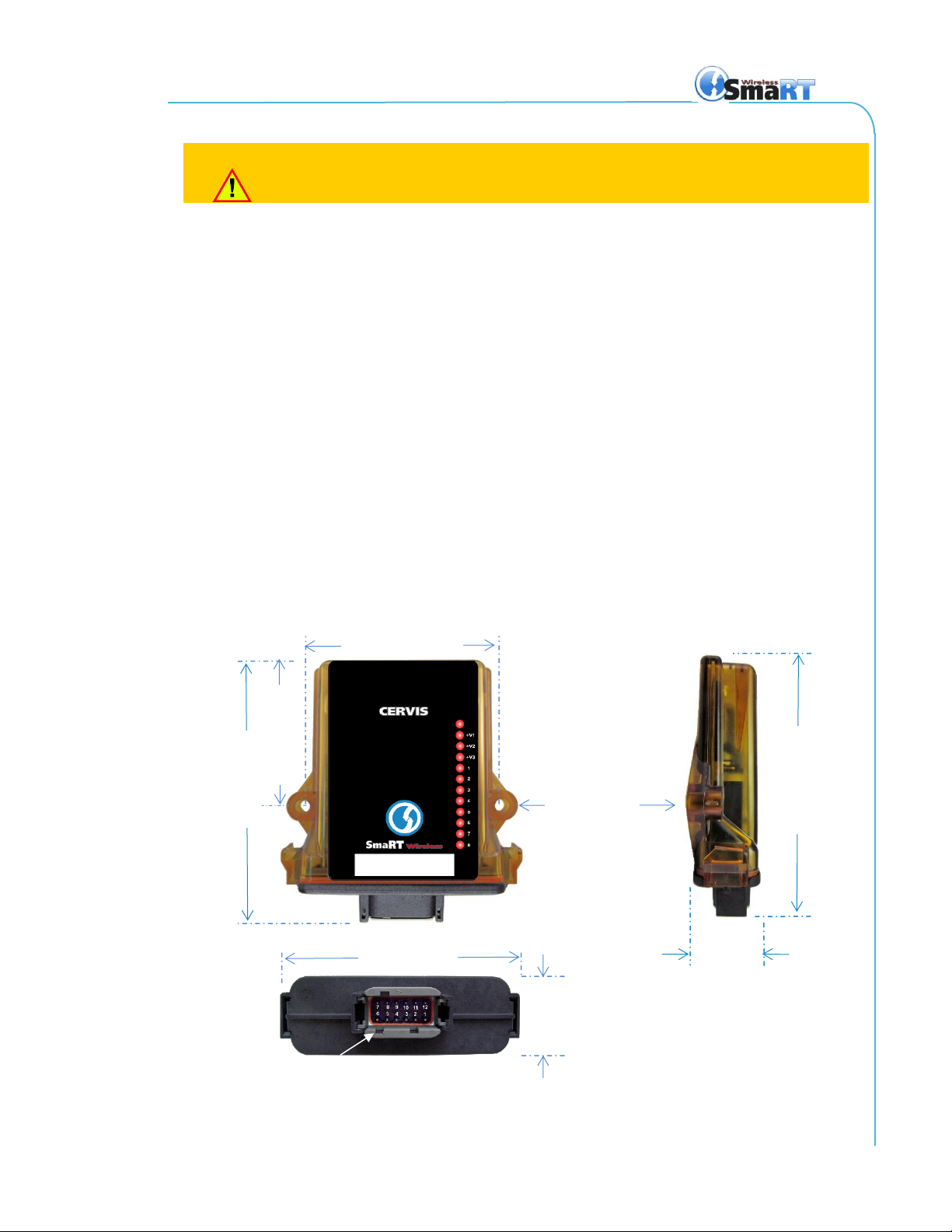
Figure 4. Base Unit Installation Dimensions
36mm (1.4")
P1
133mm (5.25")
Install with P1 facing DOWN.
P1
133mm (5.25")
36mm (1.4")
118mm (4.7")
102mm (4") centers
74.9mm (2.95")
7.4mm (0.29")
dia. mounting
holes.
SmaRT BU-xH8D Base Unit Family
U088.4.4-SmaRT_BU-xH8D
4
2.2 Base Unit Power
Power is supplied to the base unit though the harness cable. The cable attaches to the base unit
P1 connector. Power can be removed from the base unit by disconnecting the 12-pin cable
connector from the base unit P1 socket. To remove the cable connector from P1, pinch the
latching ears of the connector (Figure 6) and pull the connector away from the unit.
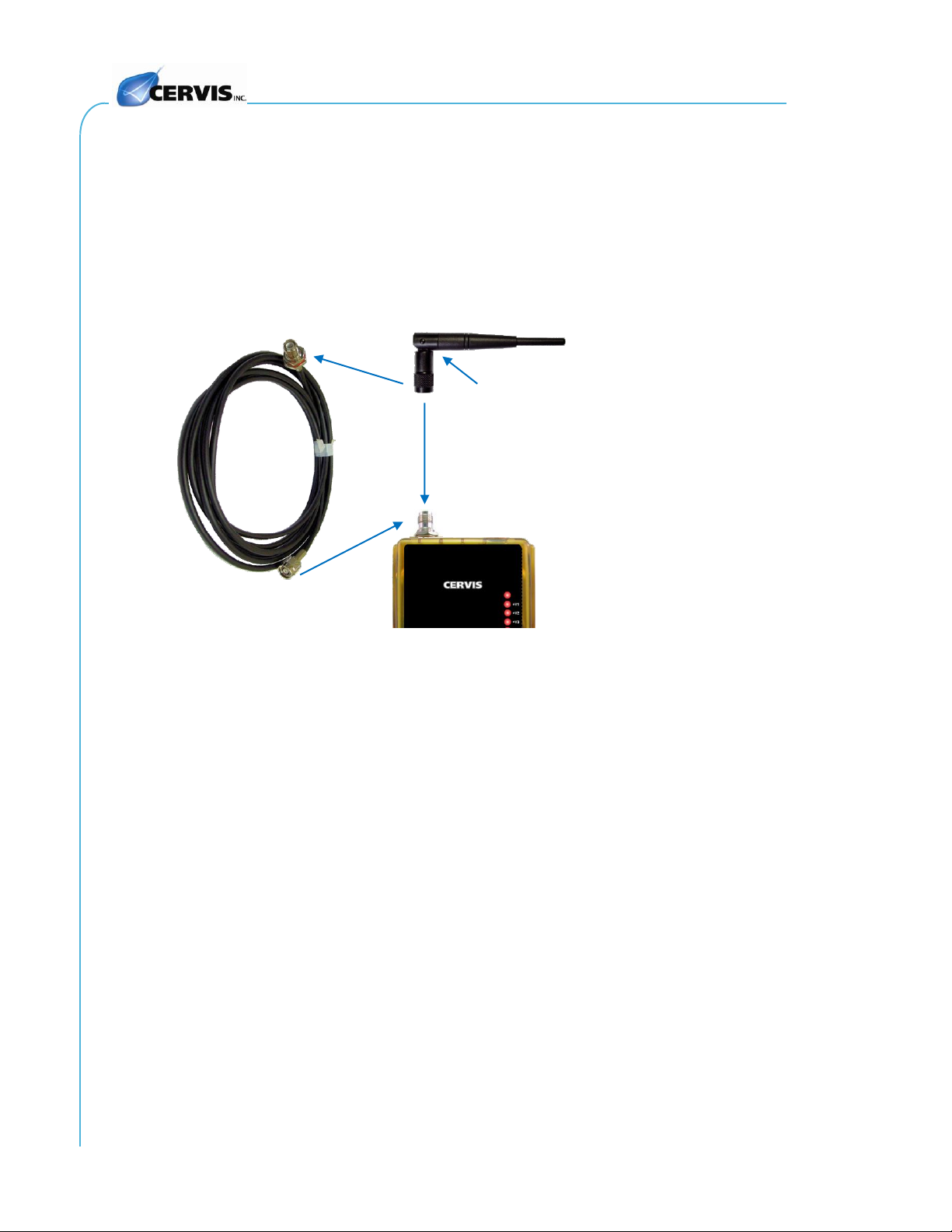
2.3 Base Unit External Antenna
A base unit 900MHz or 2.4GHz external antenna attaches to the base unit using the connector
shown in Figure 5. Extensions and extension kits are available. See Table 3 for detailed
information.
Figure 5. BU-xH8D with External Antenna and Extension Cable
Connector
2.4GHz (or 900MHz)
Antenna
Antenna Extension Cable

900MHz and 2.4MHz Manual
2019 Cervis, Inc.
5
2.4 Base Unit Cable and Field Wiring
Note: Harness cable wires are individually marked on each wire’s insulator. Connect
negative VDC (–VDC) directly to the power supply negative terminal.
Figure 6. HN-1001 Wiring Harness Cable
Table 1. BU-xH8D Variant Wiring Table
Connection
BU-2H8D
BU-9H8D
BU-2H8D-CAN
BU-9H8D-CAN
P1:1
+VDC
+VDC
P1:2
M7
M7
P1:3
M1
M1
P1:4
M2
M2
P1:5
M3
M3
P1:6
M4
M4
P1:7
RS-232 TX
CANH
P1:8
RS-232 RX
CANL
P1:9
M8
M8
P1:10
M5
M5
P1:11
M6
M6
P1:12
–VDC
–VDC
Caution
To protect against short circuits, make sure the ends of all unused
wires are insulated when making your connections.
Pinch ears and pull connector to remove from the base unit P1.

SmaRT BU-xH8D Base Unit Family
U088.4.4-SmaRT_BU-xH8D
6
3.0 BU-xH8D Operation
Initial Use Instructions
You must have a clear line of sight to and be within range of the base unit while operating
a SmaRT wireless remote.
Each BU-xH8D typically can establish communication links with as many as eight different
SmaRT PTO, DO, OO, pistol-grip, CB, and MCB remotes; or, with another SmaRT base
unit. Each wireless remote used must Associate to establish communications with the base
unit. Systems are associated at Cervis, Inc. before shipping. But, when necessary, the
Associate procedure (see Appendix C) can be used to establish communications.
Verify that the HN-1001 harness connections to the controlled device(s) are correct and
that the wiring harness is firmly plugged into the BU-xH8D base unit P1.
When necessary to remove power from the BU-xH8D, disconnect the wiring harness
connector from base unit P1 or remove the power source from the base unit.

900MHz and 2.4MHz Manual
2019 Cervis, Inc.
7
4.0 BU-xH8D Base Unit Specifications
Table 2. BU-xH8D Base Unit Specifications
Item
Description
Power
Vin +7 to +28VDC
Operating Power 1W nominal
Environment
Operating Temp –40°C to 70°C (–40°F to 158°F)
Storage Temp –40°C to 85°C (–40°F to 185°F)
Humidity 0 to 100%
Vibration/Shock IEC60068-2-6
10Hz to 150Hz @ 1.0gpeak acceleration
10.0gpeak shock acceleration
Radio
Frequency 2405–2480MHz @ 100mW
906–924MHz @ 10mW
License No license required
Modulation DSSS
Antenna Internal or External
Enclosure
Dimensions mm: 133 x 118 x 36
Inches: 5.24 x 4.65 x 1.42
Weight 0.24kg. (8oz.)
Durability High Impact Polymer
Indicators
Unnamed Vin polarity reversed when lit steady
+V1, +V2, +V3 OK when lit steady
1 Health (blinks once per second when active)
2 RF TX (flashes when active)
3 RF RX (flashes when active)
4 CAN TX (flashes when active)
5 CAN RX (flashes when active)
6 Output (blinks once per second when active)
7 Input (blinks once per second when active)
8 Error (solid when active)
Outputs/Inputs
(Eight total)
Outputs (6 or 8) Open-Drain FETs, high-side or low-side switching
2.5A max. each output
8A max. total output @ 55°C (131°F)
PWM Range: 30Hz to 200Hz
Analog (2) 0–10V/4–20mA input (M7 and M8 when chosen)
(optional) 0–10V output (M7 and M8 when chosen)
Note: BU-xH8D-CAN units are internally terminated at 1.2K
. Termination can be removed
at the factory.

SmaRT BU-xH8D Base Unit Family
U088.4.4-SmaRT_BU-xH8D
8
5.0 BU-xH8D (BU-xH8D-EXT) Antenna and Cable List
Table 3. Compatible BU-xH8D (BU-xH8D-EXT) External Antenna Details
Part
Cervis BIN
2.4GHz Swivel Antenna, +3dBi
BB3-07
900MHz Swivel Antenna, +3dBi
BB3-06
3 ft. antenna extension cable
J5-07
10 ft. antenna extension cable
J5-02
10 ft. antenna cable (J5-02) and external antenna (BB3-06)
EXT-10-900
3 ft. antenna cable (J5-07) and external antenna (BB3-06)
EXT-3-900
Note: Only use the antenna recommended by Cervis, Inc. with the SmaRT base unit.
Table 4. Compatible BU-xH8D P1 Cable
Item
Part #
Wiring Harness
P1 Cable
BB6-01
HN-1001

900MHz and 2.4MHz Manual
2019 Cervis, Inc.
9
6.0 SmaRT BU-xH8D Base Unit Variations
2.4GHz and 900MHz Common Features:
Input Power 7–28VDC; No Suppression
Table 5. SmaRT BU-2H8D Base Unit Variations
Model
Operating
Frequency
RF
Power
FET
Channels
Antenna
Type
Analog
Channels
Serial
Port
Display
BU-2H8D-INT-AV2
2.4GHz
100mW
8
Internal
(2) 0–10V IN
RS-232
No
BU-2H8D-EXT-AV2
2.4GHz
100mW
8
External
(2) 0–10V IN
RS-232
No
BU-2H8D-INT-AV2-CAN
2.4GHz
100mW
8
Internal
(2) 0–10V IN
CAN
No
BU-2H8D-EXT-AV2-CAN
2.4GHz
100mW
8
External
(2) 0–10V IN
CAN
No
BU-2H8D-INT-AI2
2.4GHz
100mW
8
Internal
(2) 4–20mA IN
RS-232
No
BU-2H8D-EXT-AI2
2.4GHz
100mW
8
External
(2) 4–20mA IN
RS-232
No
BU-2H8D-INT-AI2-CAN
2.4GHz
100mW
8
Internal
(2) 4–20mA IN
CAN
No
BU-2H8D-EXT-AI2-CAN
2.4GHz
100mW
8
External
(2) 4–20mA IN
CAN
No
BU-2H8D-INT-AO2
2.4GHz
100mW
8
Internal
(2) 0–10V OUT
RS-232
No
BU-2H8D-EXT-AO2
2.4GHz
100mW
8
External
(2) 0–10V OUT
RS-232
No
BU-2H8D-INT-AO2-CAN
2.4GHz
100mW
8
Internal
(2) 0–10V OUT
CAN
No
BU-2H8D-EXT-AO2-CAN
2.4GHz
100mW
8
External
(2) 0–10V OUT
CAN
No
BU-2H8D-INT
2.4GHz
100mW
8
Internal
N/A
RS-232
No
BU-2H8D-EXT
2.4GHz
100mW
8
External
N/A
RS-232
No
BU-2H8D-INT-CAN
2.4GHz
100mW
8
Internal
N/A
CAN
No
BU-2H8D-EXT-CAN
2.4GHz
100mW
8
External
N/A
CAN
No
BU-2H8D-INT-DIS-AV2
2.4GHz
100mW
8
Internal
(2) 0–10V IN
RS-232
Yes
BU-2H8D-EXT-DIS-AV2
2.4GHz
100mW
8
External
(2) 0–10V IN
RS-232
Yes
BU-2H8D-INT-DIS-AV2-CAN
2.4GHz
100mW
8
Internal
(2) 0–10V IN
CAN
Yes
BU-2H8D-EXT-DIS-AV2-CAN
2.4GHz
100mW
8
External
(2) 0–10V IN
CAN
Yes
BU-2H8D-INT-DIS-AI2
2.4GHz
100mW
8
Internal
(2) 4–20mA IN
RS-232
Yes
BU-2H8D-EXT-DIS-AI2
2.4GHz
100mW
8
External
(2) 4–20mA IN
RS-232
Yes
BU-2H8D-INT-DIS-AI2-CAN
2.4GHz
100mW
8
Internal
(2) 4–20mA IN
CAN
Yes
BU-2H8D-EXT-DIS-AI2-CAN
2.4GHz
100mW
8
External
(2) 4–20mA IN
CAN
Yes
BU-2H8D-INT-DIS-AO2
2.4GHz
100mW
8
Internal
(2) 0–10V OUT
RS-232
Yes
BU-2H8D-EXT-DIS-AO2
2.4GHz
100mW
8
External
(2) 0–10V OUT
RS-232
Yes
BU-2H8D-INT-DIS-AO2-CAN
2.4GHz
100mW
8
Internal
(2) 0–10V OUT
CAN
Yes
BU-2H8D-EXT-DIS-AO2-CAN
2.4GHz
100mW
8
External
(2) 0–10V OUT
CAN
Yes
BU-2H8D-INT-DIS
2.4GHz
100mW
8
Internal
N/A
RS-232
Yes
BU-2H8D-EXT-DIS
2.4GHz
100mW
8
External
N/A
RS-232
Yes
BU-2H8D-INT-DIS-CAN
2.4GHz
100mW
8
Internal
N/A
CAN
Yes
BU-2H8D-EXT-DIS-CAN
2.4GHz
100mW
8
External
N/A
CAN
Yes

SmaRT BU-xH8D Base Unit Family
U088.4.4-SmaRT_BU-xH8D
10
Table 6. SmaRT BU-9H8D Base Unit Variations
Model
Operating
Frequency
RF
Power
FET
Channels
Antenna
Type
Analog
Channels
Serial
Port
Display
BU-9H8D-INT-AV2
900MHz
10mW
8
Internal
(2) 0–10V IN
RS-232
No
BU-9H8D-EXT-AV2
900MHz
10mW
8
External
(2) 0–10V IN
RS-232
No
BU-9H8D-INT-AV2-CAN
900MHz
10mW
8
Internal
(2) 0–10V IN
CAN
No
BU-9H8D-EXT-AV2-CAN
900MHz
10mW
8
External
(2) 0–10V IN
CAN
No
BU-9H8D-INT-AI2
900MHz
10mW
8
Internal
(2) 4–20mA IN
RS-232
No
BU-9H8D-EXT-AI2
900MHz
10mW
8
External
(2) 4–20mA IN
RS-232
No
BU-9H8D-INT-AI2-CAN
900MHz
10mW
8
Internal
(2) 4–20mA IN
CAN
No
BU-9H8D-EXT-AI2-CAN
900MHz
10mW
8
External
(2) 4–20mA IN
CAN
No
BU-9H8D-INT-AO2
900MHz
10mW
8
Internal
(2) 0–10V OUT
RS-232
No
BU-9H8D-EXT-AO2
900MHz
10mW
8
External
(2) 0–10V OUT
RS-232
No
BU-9H8D-INT-AO2-CAN
900MHz
10mW
8
Internal
(2) 0–10V OUT
CAN
No
BU-9H8D-EXT-AO2-CAN
900MHz
10mW
8
External
(2) 0–10V OUT
CAN
No
BU-9H8D-INT
900MHz
10mW
8
Internal
N/A
RS-232
No
BU-9H8D-EXT
900MHz
10mW
8
External
N/A
RS-232
No
BU-9H8D-INT-CAN
900MHz
10mW
8
Internal
N/A
CAN
No
BU-9H8D-EXT-CAN
900MHz
10mW
8
External
N/A
CAN
No
BU-9H8D-INT-DIS-AV2
900MHz
10mW
8
Internal
(2) 0–10V IN
RS-232
Yes
BU-9H8D-EXT-DIS-AV2
900MHz
10mW
8
External
(2) 0–10V IN
RS-232
Yes
BU-9H8D-INT-DIS-AV2-CAN
900MHz
10mW
8
Internal
(2) 0–10V IN
CAN
Yes
BU-9H8D-EXT-DIS-AV2-CAN
900MHz
10mW
8
External
(2) 0–10V IN
CAN
Yes
BU-9H8D-INT-DIS-AI2
900MHz
10mW
8
Internal
(2) 4–20mA IN
RS-232
Yes
BU-9H8D-EXT-DIS-AI2
900MHz
10mW
8
External
(2) 4–20mA IN
RS-232
Yes
BU-9H8D-INT-DIS-AI2-CAN
900MHz
10mW
8
Internal
(2) 4–20mA IN
CAN
Yes
BU-9H8D-EXT-DIS-AI2-CAN
900MHz
10mW
8
External
(2) 4–20mA IN
CAN
Yes
BU-9H8D-INT-DIS-AO2
900MHz
10mW
8
Internal
(2) 0–10V OUT
RS-232
Yes
BU-9H8D-EXT-DIS-AO2
900MHz
10mW
8
External
(2) 0–10V OUT
RS-232
Yes
BU-9H8D-INT-DIS-AO2-CAN
900MHz
10mW
8
Internal
(2) 0–10V OUT
CAN
Yes
BU-9H8D-EXT-DIS-AO2-CAN
900MHz
10mW
8
External
(2) 0–10V OUT
CAN
Yes
BU-9H8D-INT-DIS
900MHz
10mW
8
Internal
N/A
RS-232
Yes
BU-9H8D-EXT-DIS
900MHz
10mW
8
External
N/A
RS-232
Yes
BU-9H8D-INT-DIS-CAN
900MHz
10mW
8
Internal
N/A
CAN
Yes
BU-9H8D-EXT-DIS-CAN
900MHz
10mW
8
External
N/A
CAN
Yes
Note: BU-xH8D-CAN units are internally terminated at 1.2K
. Termination can be removed
at the factory.

900MHz and 2.4MHz Manual
2019 Cervis, Inc.
11
Appendix A: Exposure to Radio Frequency Energy
SmaRT base units contain radio transceivers. When active, a base unit sends out radio
frequency (RF) energy through its internal or external antenna. The SmaRT base unit complies
with limits set by the United States Federal Communications Commission (FCC) for operating
distance from human tissue.
Appendix B: Agency Identification Label Locations
Figure 7. Agency Identification Label Locations
Note: The base unit label position is
identical for both internal antenna and
external antenna base units.
Note: Individual agency labels may
differ, but SmaRT base unit models use
the illustrated label position for all base
unit agency labels.

SmaRT BU-xH8D Base Unit Family
U088.4.4-SmaRT_BU-xH8D
12
Appendix C: Typical Handheld to Base Unit Communication
Handheld remote and base unit communications are established at Cervis, Inc. before shipping
when systems are ordered. However, it may be necessary to establish or re-establish
communication between a remote and a base unit at some point. The Associate procedure is
used to do this.
A standard SmaRT System consists of one handheld remote and one base unit. Each base unit
can communicate with up to eight handheld remotes. Each handheld must first establish a
communications link with the base unit before the base unit will recognize the handheld unit.
This process is called “Association.”
In some cases, it may become necessary to break the communication link between the
handheld and the BU-xH8D. This process is called “Dissociation.”Be aware that when a
handheld is dissociated from a base unit, all communication links to that particular base unit are
erased from the base unit memory! For instance, a particular BU-xH8D is associated to
Handheld Remotes 1 through 5. Remote 2 dissociates—breaks the communication link—from
the base unit. All five handheld remotes are removed from the base unit memory. The Associate
procedure must be used by any handheld that now needs to control that BU-xH8D.
The following Associate and Dissociate procedures are general methods of associating or
dissociating Cervis, Inc. handheld remotes to the BU-xH8D. Custom systems may have different
Association methods unique to the custom system design.
C1: BU-xH8D/PTO-DO-OO Remote Communication
To Associate
The base unit and handheld must be OFF before attempting to associate. Base unit and SmaRT
2-, 4-, and 6-button handheld association is established using the following steps:
1. Remove power from the base unit and turn off (PTO –time out) the handheld
device.
2. Stand near the base unit in unobstructed, clear line-of-sight with the handheld in
hand.
3. Simultaneously press and hold the Associate (B1) and Dissociate (B2) buttons.
The RX and ER LEDs light.
4. Continue to hold both buttons until the TX and RX LEDs light steady.
5. When the TX and RX LEDs light, release buttons B1 and B2. The ER and BA
LEDs light.
Note: If the next button is not immediately pressed (in approximately 2 seconds), all LEDs
flash and the Associate procedure is aborted. You must restart the process to establish
the communication link.
6. Immediately press and hold the Associate button (B1). All LEDs light.
7. The TX LED begins to slowly blink. Continue to hold button B1.
8. Apply power to the base unit.
The handheld and base unit begin to establish a communication link while the Associate button
is held. Once the process is complete, all LEDs light briefly and then go out.
9. Release the Associate button. The SmaRT System is ready for use with that
particular handheld remote.

900MHz and 2.4MHz Manual
2019 Cervis, Inc.
13
Figure 8. XX-2, 4, 6 Handheld Associate/Dissociate Buttons
Associate to
base unit
Dissociate
from
base unit
B1
TX
ER
RX
B2

SmaRT BU-xH8D Base Unit Family
U088.4.4-SmaRT_BU-xH8D
14
To Dissociate
In some circumstances, it may become necessary to break the communication link—or
dissociate—a base unit and a PTO handheld remote.
Caution
Using the following steps breaks all previously established handheld remote links.
It will be necessary to perform the Association Procedure (Appendix C1, above)
using each handheld to re-establish communication links with a base unit.
1. Remove power from the base unit.
2. Stand near the base unit in line of sight with the handheld in your hand.
3. Press and hold both the Associate button (B1) and Dissociate button (B2), see
Figure 8). The RX and ER LEDs light.
4. Continue to hold both buttons until the TX and RX LEDs light steady.
5. When the TX and RX LEDs light, release buttons B1 and B2. The ER and BA
LEDs light.
Note: If the next button is not pressed within the two-second interval, all LEDs flash
and the procedure is aborted. Restart the process to break the communication link.
6. Press and hold the Dissociate button (B2). (See Figure 8 above.) All LEDs light.
7. The TX LED begins to slowly blink. Continue to hold B2.
8. Apply power to the base unit while continuing to hold the Dissociate button.
The base unit and all previously linked handhelds begin to Dissociate communication links.
Once the process is complete, all LEDs light briefly and then go out.
9. Release the Dissociate button (B2).
The SmaRT base unit will not communicate with any handheld remote units. A handheld remote
must use the Association Procedure (Appendix C1) to re-establish a communication link with the
base unit.
This manual suits for next models
4
Table of contents
Other Cervis Accessories manuals


