Cervoz MEC-DIS-M002 User manual

MEC-DIS-M002
Mini PCI-e DVI/VGA output graphic board
User’s Manual
Third Edition, February 2014
© 2014 Cervoz Co., Ltd. All rights reserved.
Reproduction without permission is prohibited

2
Mini PCI-e Graphic Card
User’s Manual
The software described in this manual is furnished under a license agreement and may be
used only in accordance with the terms of that agreement.
Copyright Notice
© 2014 Cervoz Co., Ltd. All rights reserved. Reproduction without permission is prohibited.
Trademarks
Cervoz is a registered trademark of Cervoz Co., Ltd. All other trademarks or registered marks
in this manual belong to their respective manufacturers.
Disclaimer
Information in this document is subject to change without notice and does not represent a
commitment on the part of Cervoz.
Cervoz provides this document “as is,” without warranty of any kind, either expressed or
implied, including, but not limited to, its particular purpose. Cervoz reserves the right to make
improvements and/or changes to this manual, or to the products and/or the programs
described in this manual, at any time.
Information provided in this manual is intended to be accurate and reliable. However, Cervoz
assumes no responsibility for its use, or for any infringements on the rights of third parties that
may result from its use.
This product might include unintentional technical or typographical errors. Changes are
periodically made to the information herein to correct such errors, and these changes are
incorporated into new editions of the publication.
Technical Support Contact Information
http://www.cervoz.com/support/technical.php
Cervoz Co., Ltd.
Tel: +886-2-2911-9599
Fax: +886-2-2911-9566

3
Table of Contents
Chapter 1
Introduction
4
Overviews
4
Features
4
Installation Flowchart
5
Package Checklist
5
Chapter 2
Hardware Installation
6
Chapter 3
Software Installation
12
Chapter 4
Troubleshooting
21
Appendix
Pin Assignments
22
Board Side Pin Assignments
23
Device Side Pin Assignments
23
Technical Reference
24
MEC-DIS-M002 Specifications
24
MEC-DIS-M002 Dimensions
25
MEC-DIS-M002 Daughter Board Dimensions
25
Product Warranty Statement
26

4
1
Introduction
Overview
MEC-DIS-M002 is a graphic card for embedded PC. The card follows the Mini PCI-e
standard which is complaint with PCI Express x 1 classification and small form factor
(30.00 x 50.95 mm). This board fits in any host computer that has Mini PCI-e card
slots.
Features
The PCI Express boards have the following outstanding features:
Single-Lane (x1) PCI-Express with throughput up to 2.5Gbps
Fully compliant with PCI-Express Base Specification Rev 1.1
Support simultaneously dual display output
Industry- Leading 2D acceleration graphic engine
On board video memory with 16MB DDR SDRAM
Support 1280 x 1024 @ 60Hz DVI /VGA resolution

5
Installation Flowchart
Installation Flowchart of MEC-DIS-M002
The following flowchart provides a brief summary of the procedure you should follow to
install the Mini PCI-e card:
Package Checklist
The following items are included in the Mini PCI Express board Package:
Mini PCI-e Card x 1
Daughter board (DVI-I connector) x 1
Bracket x 1
M2.5 Screw x 2
20Pin Internal Connection Cable (30cm) x 1
Quick Installation Guide (Printed) x 1
Driver CD x 1
Note: Notify your sales representative if any of the above items are missing or
damaged.
Connect the internal cable
Hardware Installation
Install the card in the Mini PCI-e slot
Connector Fixation
Software Installation
Install the driver
Hardware Installation
Hardware Installation

6
2
Hardware Installation
This chapter describes the PCI Express Series hardware installation procedure. Since the
BIOS automatically assign the PCI Express board’s IRQ number and I/O addresses, you must
plug in the board before installing the driver.
Step 1
Connect the internal cable to the card
Connect the internal cable to the card
Note
Both sides of the cable connectors are the same, it doesn’t matter which side
you connect

7
Step 2
Install the card to the Mini PCI-e slot
Make sure you install the card in the right position (fool-proof design)
Step 3
Fix the card on the motherboard (clip type or screw type)
There are 2 options to fix the card. It depends on the design of the motherboard (clip or
screw).
1. Clip type: make sure you press down the card and let the clips fix the card
2. Screw type: make sure you tighten up the screws to fix the card

8
Step 4
Card installation completed
Find any place on mother board that you can screw the ground cable.
Step 5
Connect the cable to the daughter board
1. Connect other side of the cable to the daughter board
2. Connect the ground cable on daughter board or chassis or mother board where you
can screw it.
Note
1. Both sides of the cable connectors are the same, it doesn’t matter which
side you connect
2. Please contact your sales representative if you wish to purchase a
DVI+VGA Y-cable

9
Connector Fixation
MECFIX –Versatile Mounting
1. Standard PCI/PCIe Bracket
PCI / PCIe IO Bracket
2. Low Profile PCI/PCIe Bracket
Low Profile IO Bracket

10
3. Internal Mounting
Upper Fixation –Industrial System
Right & Left Fixation –Industrial System
11
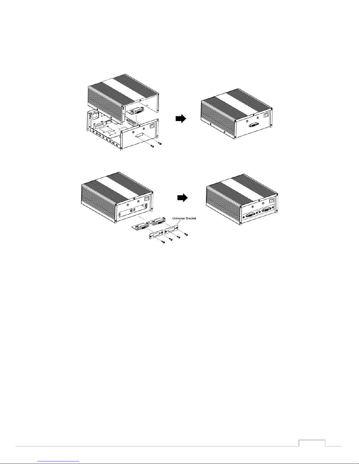
4. Customized Front / Rear Plate
Front / Rear I/O Plate
Universal Bracket
12
3
Software Installation
This chapter gives installation, configuration, and update/removal procedures for the driver for
Win 2003, Win XP, Win Vista, Win 7, and Win 8.
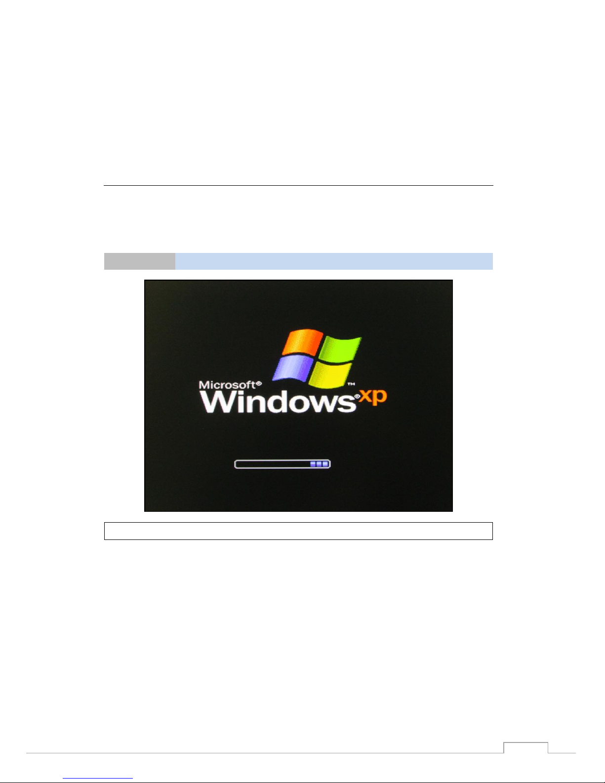
Step 1
Turn on PC and start Windows
Note
XP OS as example

13
Step 2
Windows automatically detects the new device
1. If the card is installed properly, system would detect the new device and the hardware
wizard would start automatically.
2. Click “Cancel” to disregard
Step 3
Insert CD
Open the CD drive

14
Step 4
Find the “MEC-DIS-M002” folder
Open the “MEC-DIS-M002” file folder
Step 5
Find the “Driver” folder
Open the “Driver” folder

15
Step 6
Find the appointed OS folder (Ex.: XP)
Open the appointed OS folder (We use XP as an example in the above picture)
Make sure you select the correct OS
Step 7
Find your OS version (Ex.: XP 32bit)
Select appoint OS folder (We use XP 32bit as an example in the above picture)
Make sure you select the correct version of the OS (Ex.: 32-bit or 64-bit)

16
Step 8
Find the “setup” file
Run the “set up” file
Step 9
Driver installation set up
Click “Next”
17
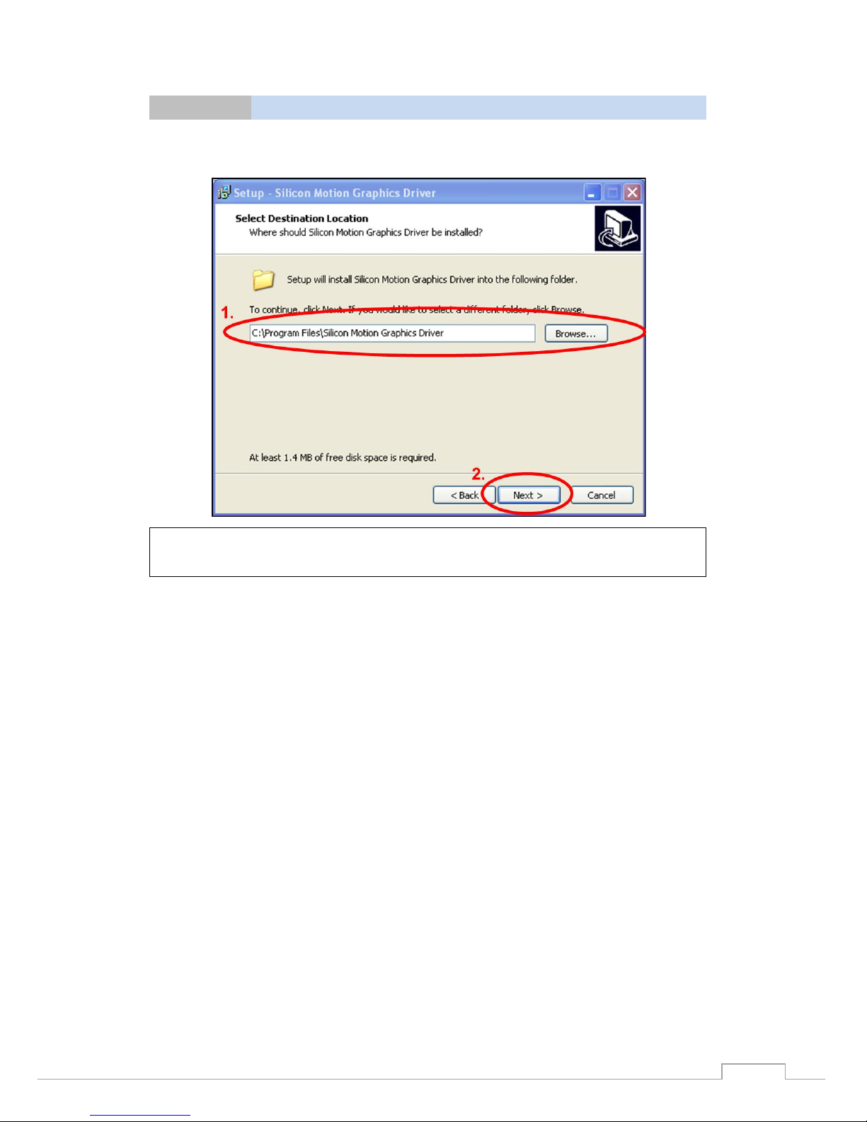
Step 10
Select destination location
1. Select the location where the driver will be installed
2. Click “Next”
Note
If you are not sure what location to be installed, keep the default setting and
click “Next”.

18
Step 11
Select Start Menu folder
1. Select the start menu folder
2. Click “Next”
Note
Note: If you are not sure what folder to be selected, keep the default setting
and click “Next”.
Step 12
Start driver installation
Click ”Install”

19
Step 13
Installation in progress
Step 14
Disregard logo testing
1. Before installation is completed, logo testing window would pop out. Disregard this
information and continue the installation progress
2. Click “Continue Anyway”
20
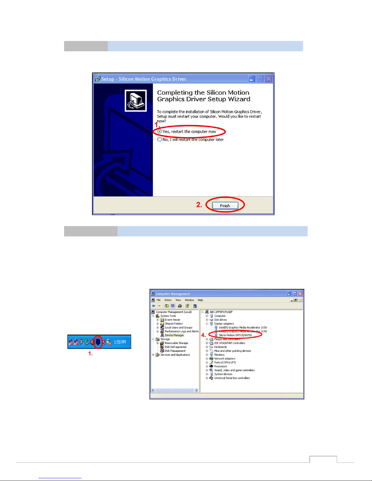
Step 15
Driver installation completed, restart PC
1. Select “Yes, restart the computer now”
2. Click “Finish”
Step 16
Confirm if driver is installed
1. When you restart Windows, you would find the SMI icon on the right bottom corner
2. Start “Computer Management” program
3. Go to the route: My Computer
→
Manage
→
Device Manager
→
Display adapters
4. You would find the driver name: Silicon Motion SM718/SM750
5. Device is ready to be used
Table of contents
Popular Video Card manuals by other brands

Diamond Multimedia
Diamond Multimedia ATI Radeon SKU 4870PE51GDT Specification sheet

NEC
NEC N8116-29 user guide

ATI Technologies
ATI Technologies RADEON 137-40225-20 user guide

MSI
MSI N220GT series user manual

ATI Technologies
ATI Technologies RADEON 7000 MAC EDITION user guide

SIIG
SIIG aurora Quick installation guide


