Ceteor Propulstation Booster 12V User manual

2 - 19English
Booster 12/24V
Instruc ons for use
EN
1-A

2
Attention
General information
Description
Voltmeter
Alternator Testing
LED Clamp
AC Docking station - Workshop
DC Docking station - Vehicle
Instruction manual
To start a vehicle
Vehicle 24V - Detection of the 24V
Inversion of polarity
Starting attempt
Protection
Voltage detection system
Storage of your Booster
Preventing premature failure of your Booster’s batteries
Recharging
Starting
Remark
Questions – Answers
My Booster
General
Electronic components of vehicles
History
Car manufacturers’ recommendations
High voltage surge
Warranty
1.
2.
2.1.
2.2.
2.3.
2.4.
2.5.
2.6.
3.
3.1.
3.2.
3.3.
3.4.
3.5.
3.6.
3.7.
4.
4.1.
4.2.
4.3.
5.
5.1.
5.2.
6.
6.1.
6.2.
6.3.
7.
Instructions for use
Congratulations, you are now the owner of a Battery Booster PROPULSTATION®,
the only jump starter with a docking station !
Chosen by the professionals all over the world for its power and reliability,
it will bring you an incomparable pleasure of use.
To prolong the lifetime of your new PROPULSTATION® and use it safely, we invite you
to read and follow the recommendations of this user’s manual.
.......... 57
.......... 57
.......... 58
.......... 58
.......... 58
.......... 58
.......... 59
.......... 60
.......... 62
.......... 63
.......... 64
.......... 64
.......... 65
.......... 65
.......... 66
.......... 67
.......... 69
.......... 70
.......... 71
.......... 72
.......... 72
.......... 72
.......... 73

3
1
12V 24V
2 3 4 5
6
7
8
9
10
1. Cauon
Read attentively the user manual before first use !!!
Failure to comply with the instructions can lead to damages or an explosion.
Always use the Booster in well ventilated areas, and wear eye protection and gloves.
Always use the Booster in a non conductive and non polluting atmosphere.
Never charge or jump-start a vehicle with a frozen battery.
This equipment may not be used by children or by those who can not read and under-
stand the manual. Store, use and charge the Booster out of the reach of children and
unauthorized persons.
Never store your Booster in its station if this one is not connected to a vehicle or to the
mains.
After receipt, connect the docking station and put your booster on charge for 24 hours,
before use.
2. General informaon
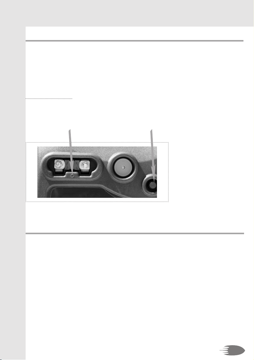
2.1. Descripon
Power fuse
Buzzer
Push button for voltmeter
Voltmeter
Vehicle’s voltage detection
Charging connector
2 Automatic 16A fuses to protect the charging connector
Tension selector
Hydrogen escape orifice
Reserve power fuse
n
n
n
n
n
n
n
1.
2.
3.
4.
5.
6.
7.
8.
9.
10.
EN

4
2.2. Voltmeter
Press the button to show the charge level of the Booster.
2.3. Alternator Tesng
After starting the engine at 2000 rpm, leave the Booster connected to the vehicle and press
the voltmeter push button. The voltmeter must indicate between 14 and 14,4 volt if the
alternator is functioning correctly.
2.4. LED Clamp
The blue clamp is provided with a LED to avoid wrong connections in the darkness. To light
the LED, push simply on the red push-button.
This LED is supplied by 3 LR44 batteries placed in the handle of the clamp (on the push-
button’s size).
2.5. AC Docking staon – Workshop
Provided with an AC/DC 230V/12V automatic and electronic maintenance charger.
The simple fact of putting the Booster back into its docking station allows it to be charged
at 100% for the next intervention. Ideally, your Booster must be charged permanently.
The station has been designed to be floor mounted with the back fixed by the 4 anchor
holes (screw M8x40 - plug 10) against a wall. The angle made by the base of the bracket
and the wall on which it is fixed must be 90° and the fixing system must resist to a wrench-
ing of 50 kg (magnets).
We highly recommend connecting the charger to a junction box to avoid any accidentally
unplugging (e.g.: by a colleague who needs to use the plug).
Make also sure that the charger is permanently supplied, some companies switch off the
main current at the end of the day -> the Booster is not charging anymore !!!
The charger is integrated to the station, so that you can make sure your Booster is charging
well.
If the light of the charger is:
Orange: your Booster is charging.
Green: your Booster is charged.
Red: the charging circuit is faulty. Warning: your Booster is not charging,
contact immediately your reseller.

5
NB: during the recharge one of the 2 voltage detection LED’s (see point 3.4.) remains
switched on.
2.6. DC docking staon - Vehicle
Developed to be connected to the recovery vehicle’s battery terminals, the simple fact of
putting the Booster back into its docking station allows it to be charged at 100% for the
next intervention.
The station must not be hung up. The angle made by the base of the bracket and the
fixing point must be 90°. This fixation must be sufficient to resist to a wrenching of 50 kg
(magnets).
Your station is delivered uncabled for recharge. Please follow the instructions
hereunder for the connection, depending on the recovery vehicle’s voltage.
DC 12V or 24V connection on the station:
Follow the diagram sticked on the station. Caution: this connection must correspond to
your vehicle’s voltage.
After the connection of the station following the diagram (12V or 24V), place the metallic
protection plate thanks to the 4 plastic rivets.
Connection on the vehicle:
This one must correspond to:
n the voltage you chose for the station.
n the voltage of the vehicle.
n Connect the black cable to the negative terminal of the battery (or the earth).
n Connect the red cable to the positive terminal of the battery.
-> For this, use the cables lugs provided for that purpose, if necessary.
A fuse of 15 or 20A can be mounted on the station circuit.
A green LED is assembled at the top of your docking station and indicates the correct
connection to the vehicle’s battery.
If you have connected your docking station to an auxiliary power supply in your vehicle, it
will be necessary to switch on the ignition or to run the engine to supply the station (green
LED).
A one-way diode installed on the docking station avoids the discharging of the Booster
towards the vehicle.
For a well charged Booster, the tension of the place where you connect the docking
station must be around 14,4V, engine running at about 2000 rpm.
NB: during the recharge one of the 2 voltage detection LED’s (see point 3.4.) remains
switched on.
EN

6
3. Instrucon manual
3.1. To start a vehicle
Turn OFF ignition before using the Booster.
The tension selector must be disconnected ! **
How to connect your Booster -> Read point 3.3.: inversion of polarity
A. Starting in 12V
Connect the red clamp (+) to the positive terminal (+) of the battery, then connect the blue
clamp (-) to the negative (-) terminal of the battery.
B. Starting in 24V -> Read point 3.2.: detection of 24V
n If the batteries are side by side:
Connect the red clamp (+) to the positive terminal (+) of the battery, then connect the
blue clamp (-) to the negative (-) terminal of the other battery.
n If the batteries are on both sides of the vehicle:
Connect the red clamp (+) to the positive terminal (+) of the battery, then connect the
blue clamp (-) to the mass of the vehicle.
Selection of the tension
First, check the voltage of the vehicle that has to be started -> to do so:
n use the detection LED’s -> Read point 3.4.: voltage detection system !!!
n in doubt, please refer to the vehicle’s instruction manual.
Plug in the selector in the correct connector ** -> from this moment there is current on
the clamps.
Start the engine -> Read point 3.5. & 3.6.
Turn the ignition key for a maximum of 8-10 seconds, wait for a further 3 minutes before
attempting to start again.
Disconnection of the tension
After starting, disconnect the tension selector.
Disconnection
Disconnect the blue (-) clamp first, followed by the red (+) clamp.
Storing -> Read point 3.7.
Return the cables and clamps to their support posts.
Recharging
After use, put the Booster immediately back in its docking station !
** Important !!! -> See point 4.2. (point 5.) : Explosion risk
1.
2.
3.
n
n
4.
5.
6.
7.
8.

12V 24V
12V 24V
12V 24V
12V 24V
2B 2B
12V 24V
34
12V 24V
12V 24V
56
12
78
1 2A
7
EN

12V 24V
8
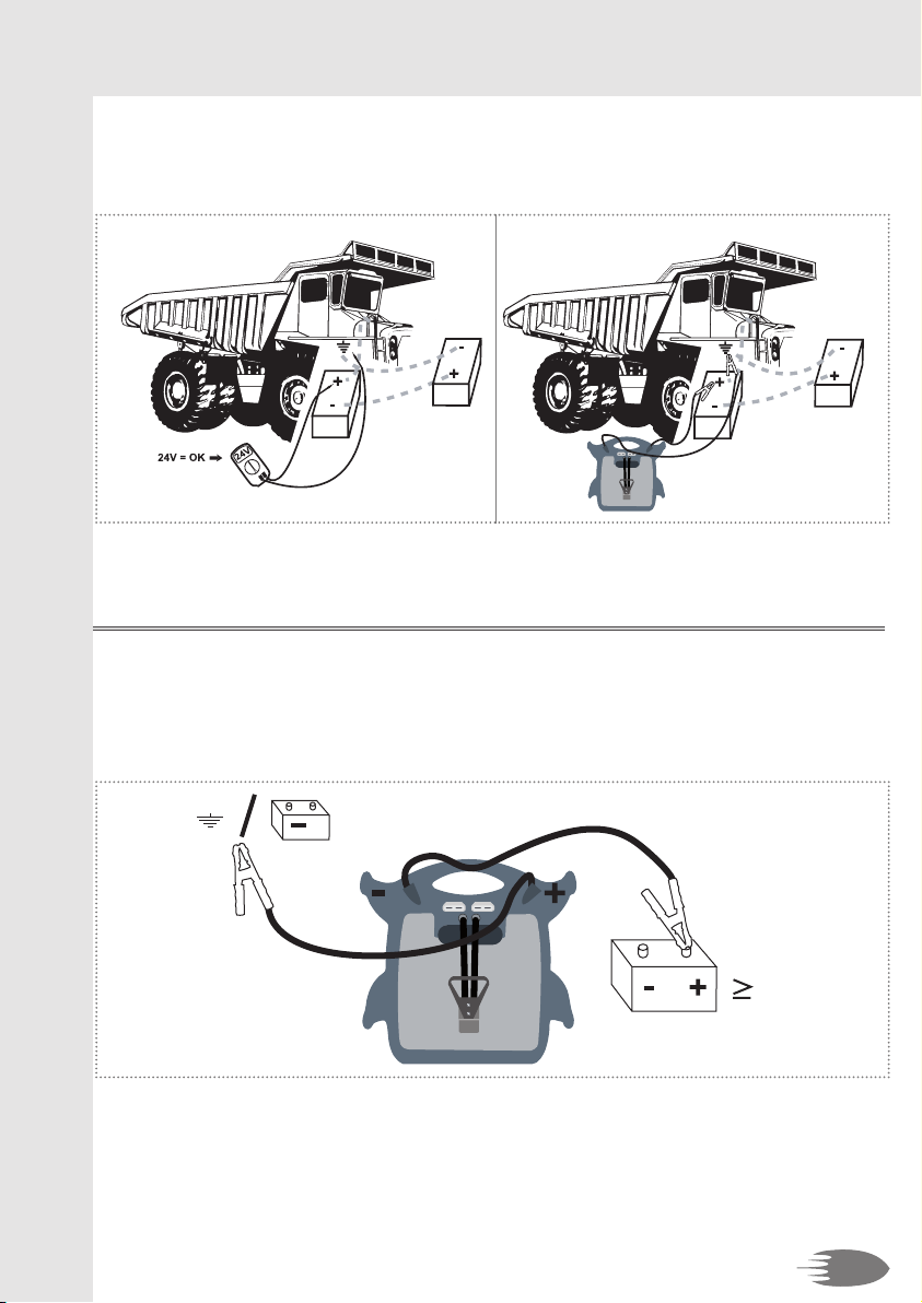
3.2. Vehicle 24V - Detecon of the 24V
Detection of 24 volt on a vehicle where the cables are not visible or when the batteries are
located on both sides of the engine bay (Caterpillar, Volvo and others large type engines).
Use a voltmeter in position DC: connect the negative to the mass of the vehicle and the
positive to the positive of a battery.
If the voltmeter indicates 12V, you are not on the right battery.
If the voltmeter indicates 24V, you are on the right battery.
n Batteries side by side
n
n
12V 24V
4V
Beeeeep
9
n Batteries located on both sides of the vehicle
3.3. Inversion of polarity
If the polarity is not right, the buzzer will give a signal:
n if the remaining voltage, in the batteries of the vehicle, is at least 4 volt.
n if the tension selector is not connected.
EN

10
3.4. Voltage detecon system
Your Booster is equipped with a voltage detection system. After the connection of the
clamps on the battery terminals of the broken down vehicle, a coloured led will indicate its
voltage, as follows:
n the green LED next to the 12V connector lights up when the voltage detected by the
Booster is between 3V and 14,4V.
n the orange LED next to the 24V connector lights up when the voltage detected by the
Booster is over 14,4V.
NB: if your vehicle does not start when the Booster is connected in 12V, it may be that your
vehicle starts in 24V:
n and that its voltage is under 14,5V
n or that you connected the Booster on the wrong vehicle’s battery (see point 3.2.).
In both cases, please read the instruction manual of the vehicle manufacturer to be sure of
the voltage of the vehicle at start.
If it is a 24V vehicle, resume the jump start considering the point 3.2.
3.5. Starng aempt
When using the Booster to start an engine, do not crank for more than 8-10
seconds, and wait for a further 3 minutes before a second attempt.
If after the 3rd attempt the engine does not start, it may be necessary to identify a further
cause for the breakdown.
NOTE: if your Booster is fully charged but the starter turns slowly, the vehicle’s or Booster’s
battery may need checking for short circuit.
11
EN
3.6. Protecon
Boosters are equipped with a power fuse. It can melt following a short circuit or a too long
start attempt, for example.
Your booster is also equipped with a spare fuse. For a quick repair, unscrew the bolts and
remove the melted fuse.
Replace it by a new fuse making sure that you correctly tighten the bolts.
To control the fuse:
Push on the button. If the blue LED under the fuse does not light up, the fuse is melted.
3.7. Storage of your Booster
The Booster can be stored in any position, without any danger for the batteries, because
those are dry batteries, pure lead.
Do not store your Booster below 0°C (32° Fahrenheit) if you want to use it urgently. Too
cold, the Booster will miss performance. The ideal operating temperature is between 10 to
25°C (50 to 77° Fahrenheit).
Clamps must always be stored on their support and never touch a metallic surface, because
there is current on the clamps during the recharge. If they are put in contact with a metal-
lic surface, the automatic 16A fuses will be released to protect the connector and your
Booster will not be charged.
n
n
n

12
1.
4. Prevenng premature failure of your Booster’s
baeries
Correctly recharging the Booster batteries, increases
its efficiency and its lifetime !
4.1. Recharging
The Booster must be imperatively put on permanent charge between use.
è Why ?
n Below 12,4V, the Booster batteries will start to sulphate and irreversible lose perform-
ance. The lower the voltage, and the longer the time spent in a discharged state, the
deeper the sulphation. When not in use, the Booster batteries must never drop below
12,4V (well-charged = 13V).
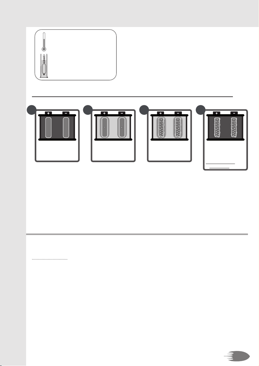
è Illustrated explanation:
n Composition of a lead-acid battery:
1/4
3/4
lead batteryelectric
charge
sulfuric acid
electrolyte
distilled water
n How does a lead-acid battery work ?
recharge
=
Return of the acid into the water
Elimination of the lead sulfate
charged battery
+/- 13V
Lead
sulfate
The acid is attracted by the
lead: forming of lead sulfate
start
=
discharge
12 3
13
2.
1.
Density of the electrolyte
charged battery : 1,28 kg/dm3
discharged battery : 1,15 kg/dm3
Frost temperature of the electrolyte
charged battery : -40°c
discharged battery : -6°c
n Consequences of several successive discharge before recharge or deep discharge:
charged battery
+/- 13V The acid is attracted by the
lead: forming of lead sulfate
start
=
discharge
12
Acid erodes the lead
Accumulation of sulfate
deeply discharged
battery +/- 11V
3
Return of the acid into the water
Traces of acid and sulfate on
the lead plates
recharged battery
irreversible damage
= loss of power
4
Never completely discharge the Booster’s batteries.
n The batteries do not have a memory effect.
n Danger of irreversible sulphatation.
4.2. Starng
Important: on vehicles difficult to start, crank the engine for a maximum of 8-10 seconds
and wait for 3 minutes before further attempt to restart the vehicle.
n Three reasons:
a. To allow the voltage of the Booster batteries to build up again.
b. To allow the renewal of gasses inside the batteries.
c. To allow the internal components of the batteries to cool down.
n If you do not wait and/or the starting attempt is too long, you risk losing power, you
reduce your starting possibilities by the second attempt and you risk melting the power
fuse.
EN
12V 24V
12V 24V
14
2.
3.
4.
Never connect the Booster to a battery or starter which is in short-circuit.
Never disconnect the Booster while engine running when there is no battery in the
vehicle or when the vehicle’s battery is at 0 volt.
n This may cause failure to the diodes of the alternator.
Never place the Booster in short-circuit, for example :
A. By connecting the red clamp (+) to the negative terminal of the battery and the
blue clamp (-) to the vehicle’s earth.
n The inversion of polarity signal will not operate because you are connected 2x to the
mass and you are not in inversion of polarity.
B. By connecting the clamps on the positive and negative terminal of the 2 batteries
which are connected together in the vehicle 24V.
n In both cases, the fuse of the battery will blow instantly.

12V 24V
15
EN
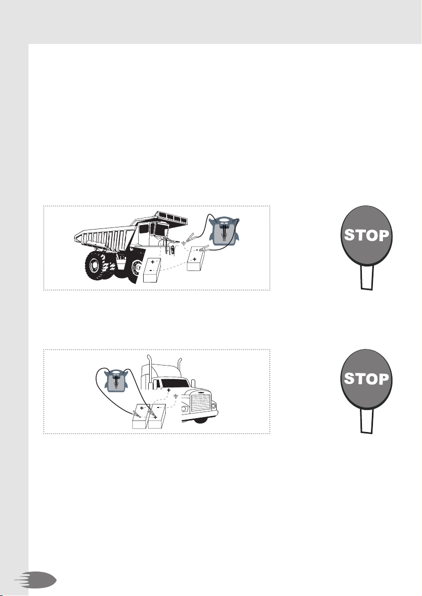
5. Explosion risk:
Never connect the Booster on a vehicle 24V when it is in position 12V.
n This incorrect connection leads to a forming of hydrogen, which can explode in presence
of a spark.
n Your Booster is equipped with a system of hydrogen escape which limits the explosion
risks in case of misuse. In that event, the hydrogen will be evacuated out of your Booster
thanks to an escape orifice, a whistle warns you of this gas production.
n If you notice that you have made this mistake, do not disconnect the tension selector,
because this may cause a spark. It is recommended to disconnect one of the clamps of
the vehicle’s battery, to move away from the Booster and to wait some minutes while the
hydrogen escapes from the Booster. Contact you reseller immediately.
NB: make sure that the escape orifice is always perfectly clean and not obstructed.
4.3. Remark
If someone else uses the Booster, ensure they are well informed on how to use it safely,
and have read and understood the operating instructions. The longevity of the Booster
depends on it.
To ensure long life and optimal use of the Booster battery,
keep it in permanent charge in its docking station.

16
A.
n
n
n
n
n
B.
n
C.
n
n
n
n
D.
n
n
5. Quesons - Answers
5.1. My Booster…
Does not recharge anymore:
There is no current on the wall socket (230V or 110V AC) on which you have
connected the charger.
The charger does not function any more.
The two 16A fuses are released (see point 3.7. (point 3)).
Verify the connections from the station’s charging plug to the vehicle’s battery.
The batteries are sulphated, swollen or « cooked » and do not take anymore the charge.
Does not work anymore in 12V, either in 24V:
The power fuse melted (see point 3.6.).
Has no power anymore:
The Booster is not charged (see point 5.1. - A).
The batteries lost its power because of:
n The sulphatation of the batteries: you did not store your Booster regularly in its
station.
n A connection of the Booster in position 12V to a vehicle 24V during a short time. *
An element inside a battery melted because of:
n Starting attempts superseding the user instructions (see point 3.5.).
A battery is « cooked » because of:
n A connection of the Booster in position 12V to a vehicle 24V. *
The voltmeter does not function:
The voltmeter or push button is broken or defective.
The tension of the batteries is below 9V.
* Attention: Explosion risk !!! (See point 4.2. (point 5.))

17
A.
B.
C.
5.2. General quesons
Can a Booster too powerful (example 12/24V-2400/1200CA) damage a small engine
(example a motor bike) ?
No, the engine will only take the necessary power to start.
How many times do I need to recharge the Booster ?
The power of the provided charger is designed to recharge the Booster at 100% overnight
(for a normal use).
Once the Booster is connected to the vehicle to jump start, do I have to make the start
attempt quickly ?
Yes, otherwise a part of the tension of the Booster will be transferred to the empty battery
of the vehicle. Your booster will be discharged for the next start.
If you have others questions or in case of a problem;
please contact your seller.
EN
(

18
6. Electronic components of vehicles
6.1. History
For more than twenty years, vehicles and engines of all kind are provided with electronic
components more and more sophisticated.
Those are perfectly compatible with the use of a Booster in contrary to the old starting
practices, still too much used and extremely dangerous for vehicle electronics and for the
health and safety of the users.
6.2. Car manufacturers’ recommendaons
Our boosters perfectly match manufacturers’ requirements. None prohibits or advises
against the use of a battery or a release booster.
Faced with the multiple requests from garage owners, some manufacturers have worked
out a process of intervention to follow if the battery fails that excludes any other form of
intervention under pain of loss of warranty.
It is, therefore, important to read the vehicle user manual before doing anything on a
vehicle’s battery.
6.3. High voltage surge
How can one damage or destroy one or more electronic components?
Answer: by provoking high voltage surges.
A high voltage surge is a small spark or a very powerful stray flash provoked by voltage
differences, short circuits or reversals of polarity, or again, and quite often, making electri-
cal welds on vehicles without disconnecting the battery or using a special Anti-Zap filter.
The small surges damage or destroy electronic components of board computers or ordinary
logic controllers.
Stray flashes and electrical welding, contrariwise, do greater damage.
If the Booster is used according to instructions, it is impossible to provoke a voltage surge.
A complete information about the electronic of vehicles is available on request.

19
7. Warranty
The Booster is guaranteed two years against all defects in material and workmanship. With
the exception of any signs of abuse, misuse or modification.
Boosters must be returned complete (with charger) freight paid and suitably packaged
preventing damage whilst in transit. Repairs carried out under warranty will be returned
free of return delivery costs.
For the LED-clamp:
The LED functions with 3 standard supplied batteries. Those are excluded of the warranty.
EN
IMPORTANT INFORMATION FOR CORRECT DISPOSAL OF THE PRODUCT IN ACCORDANCE
WITH EC DIRECTIVE 2002/96/EC.
At the end of its working life, the product must not be disposed of as urban waste.
If must be taken to a special local authority differentiated waste collection centre or to a
dealer providing this service.
Disposing of a household appliance separately avoids possible negative consequences for
the environment and health deriving from inappropriate disposal and enables the constitu-
ent materials to be recovered to obtain significant savings in energy and resources. As a
reminder of the need to dispose of household appliances separately, the product is marked
with a crossed-out wheeled dustbin.

MO PPS 12-24V- 1-A -EDV-20111017
en
This manual suits for next models
1
Table of contents
Other Ceteor Remote Starter manuals

Popular Remote Starter manuals by other brands


![Omegalink OEM-IDS(RS)-BM1-[OL-RS-BM1]-EN install guide](/data/manuals/22/t/22t7p/sources/omega-link-oem-ids-rs-bm1-ol-rs-bm1-en-manual.jpg "Omegalink OEM-IDS(RS)-BM1-[OL-RS-BM1]-EN install guide")


Menards
Menards MasterForce 260-9515 Operator's manual

Black & Decker
Black & Decker JUS500IB instruction manual

Ultra Start
Ultra Start 1600 owner's guide

Firstech
Firstech CM600-AS installation manual
Clifford
Clifford Arrow II owner's manual

Schumacher
Schumacher Jump Starter & DC Power Source PSJ-1812 owner's manual