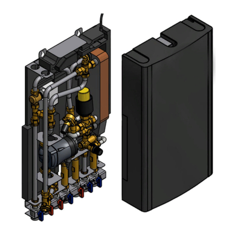
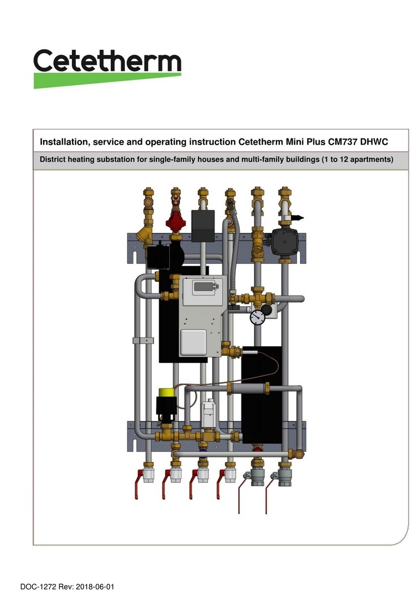
Cetetherm Mini UK Manual

DOC1586, 10-03-2021
Installation, service and operating instruction Cetetherm Mini UK
Heating & domestic hot water HIU for apartments and single family houses

This manual is published by Cetetherm.
Cetetherm can without further notice make changes and improvements to the content in this manual if it is necessary due to printing
mistakes, wrong information or changes in the hardware or software.
All these types of changes will be included in future release of the manual.
For additional on-line information, latest version of this manual please scan the qr-code or
use the link https://www.cetetherm.com/minieco-miniuk
QR-code:

Cetetherm Mini UK
Installation, service and operating instruction
3
Contents
1General information................................................................................................................ 5
Comfort......................................................................................................................................................5
Installation .................................................................................................................................................5
Long-term security.....................................................................................................................................5
CE-marking................................................................................................................................................5
Information about the document ...............................................................................................................5
General warnings ......................................................................................................................................6
2Operating instructions ........................................................................................................... 7
General operation......................................................................................................................................7
Safety equipment/inspection .....................................................................................................................7
3Product overview and flowchart ........................................................................................... 8
4Installation............................................................................................................................... 9
Unpacking..................................................................................................................................................9
Preparation................................................................................................................................................9
Mounting the HIU ......................................................................................................................................9
Filling up the system................................................................................................................................10
Filling up the tap water circuit.............................................................................................................10
Filling up and bleeding the heating circuit ...............................................................................................10
Connect to heating network ...............................................................................................................10
Commissioning advice Mini UK...............................................................................................................11
Connect the pump..............................................................................................................................11
Adjust the hot water temperature.......................................................................................................11
Set the heating temperature...............................................................................................................11
General adjustments and settings...........................................................................................................11
Dismantlement.........................................................................................................................................11
5Pump settings and pump performance .............................................................................. 12
Performance view....................................................................................................................................12
Operation status.................................................................................................................................12
Alarm status .......................................................................................................................................12
Setting view .............................................................................................................................................13
Toggling the settings of UPM3 ................................................................................................................13
Key lock function .....................................................................................................................................13
Pump curve proportional pressure mode 2, PP2 ....................................................................................14
Fault finding pump...................................................................................................................................15
6Service instructions ............................................................................................................. 16
Tap water service instructions.................................................................................................................16
Tap water temperature too low ..........................................................................................................16
Tap water temperature too high.........................................................................................................17
Hot water temperature unstable or too low ........................................................................................17
Heating system service instructions........................................................................................................17
Heating system temperature too high or too low ...............................................................................17
Heating temperature unstable............................................................................................................18
No heating ..........................................................................................................................................18
Disturbing noise from the circulation pump or the radiator system....................................................19
Heating system often needs topping up.............................................................................................19
7Service actions for the installer .......................................................................................... 20
Check the function of the actuator and valve for hot water.....................................................................20
Check the function of the actuator and valve for heating........................................................................21
Check the volume take-up and pressure equalizing of the expansion vessel ........................................21
8Maintenance and repairs...................................................................................................... 22
Cleaning the heating media filter.............................................................................................................22
Cleaning the heating circuit filter .............................................................................................................23
Change pump components or the complete pump .................................................................................24
Change the hot water actuator and heat exchanger...............................................................................25
Change the hot water valve.....................................................................................................................25

Cetetherm Mini UK
Installation, service and operating instruction
4
Change the heating actuator...................................................................................................................26
Change the heating valve........................................................................................................................27
Change the expansion vessel .................................................................................................................27
9Operating data and performance ........................................................................................ 28
Technical Data ........................................................................................................................................28
Measure sketch .......................................................................................................................................29
10 Options .................................................................................................................................. 30
Valve kit ...................................................................................................................................................30
Pipe connection up..................................................................................................................................30
Valve kit with service bypass...................................................................................................................31

Cetetherm Mini UK
Installation, service and operating instruction
5
1 General information
Cetetherm Mini UK is a complete, ready-to-install HIU for hot water and heating. It is designed for buildings with
a connection to a heating network.
Cetetherm has years of experience in heating network technology and has developed Cetetherm Mini UK with
well-planned pipe work and with all components easily accessible for inspection and future servicing.
Comfort
In Cetetherm Mini UK the hotwater and heating are set and controlled manually and maintained at the desired
temperature.
Installation
Read this manual before installing the HIU.
Compact dimensions, light weight, well arranged plumbing – all make installation very simple.
Mini UK is designed for hanging on the wall and is mounted on an insulated frame and includes an insulated
cover. Better insulation means less energy usage and better energy efficiency.
Long-term security
The heat exchanger plates and all piping are manufactured in acid-resistant stainless steel. All components are
closely matched and carefully tested for function in accordance with quality assurance system ISO 9001:2015.
For future servicing requirements, all components are accessible and individually replaceable.
CE-marking
Cetetherm Mini UK follows the rules and legislation specified in the Declaration of Conformity.
To maintain the validity of the CE marking, only identical replacement parts must be used.
Information about the document
All pictures in this document are general images.

Cetetherm Mini UK
Installation, service and operating instruction
6
General warnings
The installation work must be carried out by an authorized installation contractor. Before the
system is taken into operation, it must be pressure tested in accordance with relevant
regulations.
The temperature and the pressure of the primary heating water are very high. Only qualified
technicians are allowed to work with the HIU. Incorrect operation may cause serious personal
injury and result in damage to the building.
If the hot water temperature is set too high, people may be scalded. If the hot water
temperature is set too low, unwanted bacteriological growth may occur in the hot water system.
This can result in serious personal injury.
Parts of the HIU may get very hot and should not be touched.
When starting up the HIU: To avoid the risk of scalding, make sure that no-one draws any hot
water until the hot water temperature has been adjusted.
Start heating circulation by first opening the valves in the heating media supply and then
return lines, in order to avoid pollutions in the system. Open the valves slowly to avoid
pressure surges.
Then open heat return and then supply.
Before the HIU is connected to the electrical supply, make sure that the heating system is
topped up with water. Starting up the system without water will damage the circulation pump.
The HIU pump must be connected to an electrical plug to be connected to the main supply. If
necessary, the plug-and-socket connection can be replaced with a permanent installation with
an all-pole isolated switch. This must be carried out by a qualified electrician.

Cetetherm Mini UK
Installation, service and operating instruction
7
2 Operating instructions
General operation
The temperature and pressure of the incoming heating network water are very high. The heat from the heating
network water is transferred to the heating and hot water systems of the building in the heat exchangers. The
heat is transferred through thin plates of acid-resistant stainless steel which keep the heating network water
separate from the systems in the building.
Mini UK has a temperature control for hot water. This measures the temperature of the hot water in the heat
exchanger and automatically controls the primary flow.
The hot water temperature is controlled by a temperature control valve which is set to about 50 ºC.
If the temperature is set too high, there is a risk of scalding. Setting the hot water temperature too low may
result in unwanted bacteriological growth in the hot water system.
The heating circuit is controlled by a temperature control valve.
After adjustment, the Mini UK operates completely automatically. However, in hard water areas it is advisable
to be attentive and to remedy any faults in good time if the temperature of the hot water is too high; otherwise
the risk of lime deposits in the heat exchanger may increase.
The energy supplier registers the use of energy. Measurement is done by recording the flow of heating network
medium through the system, and by measuring the temperature difference between the medium’s supply and
return flow.
Safety equipment/inspection
•Daily inspection to check for leaks from pipes or components.
•Weekly inspection to make sure that the operation of the heating and hot water control systems is
stable and that the temperature does not fluctuate. Temperature hunting causes unnecessary wear of
valves, thermostats and heat exchangers.
•Every three months check the safety valves and the pressure in the heating system.
To check the operation of a safety valve, turn its wheel/knob until water escapes from the waste pipe of the
valve, then close the wheel/knob quickly. Occasionally a safety valve may open automatically to release excess
pressure. After a safety valve has been open it is important that it closes properly and does not drip.

Cetetherm Mini UK
Installation, service and operating instruction
8
3 Product overview and flowchart
Picture 1
Picture 2
1.
Heat exchanger and temperature controller for
hot water
13.
Safety valve for heating circuit
2.
Control valve for hot water
14.
Expansion vessel heating circuit
3.
Heat exchanger for heating
15.
Circulation pump, heating circuit
4.
Control valve, heating circuit
21.
Filter cold water
5.
Manually operated actuator, heating circuit
A.
Heating circuit, return
6.
Temperature sensor connection heating media supply,
two alternative
B.
Heating circuit, supply
7.
Filter for heating media
C.
Heating network media, supply
(primary inlet)
8.
Adapter for energy meter
D.
Heating network media, return
(primary return)
9.
Air vent valve
E.
Hot water (hw)
11.
Filter heating circuit
F.
Cold water (cw)
12.
Pressure gauge for heating circuit

Cetetherm Mini UK
Installation, service and operating instruction
9
4 Installation
Unpacking
•Remove the transport packaging and check that the product has not been damaged in transit and that
the consignment agrees with the specifications.
•When lifting the unit take care not to apply stress to pipes and heat exchanger as this may weaken
them. Avoid lifting the unit by holding the heat exchanger.
Note: Risk of injury; sharp edges and lifting heavy objects.
Preparation
•Mini UK must be placed on a wall, in upright position. Mount the unit using screws or bolts suitable for
the material of the wall and for the weight of the unit.
•Choose a suitable installation area in accordance with official regulations.
The HIU may generate sounds during operation caused by pumps, regulators systems, flows etc. This
should be taken in consideration during installation of the unit so that possible operational sounds affect
the surroundings as little as possible.
•Cetetherm recommends that:
othe HIU is mounted on a well-insulated wall, such as outer wall or on concrete wall.
oplaced in a space with a floor gully.
•Check the applicable regulations of the primary heating supplier. The available differential pressure
should be at least 50 kPa and at most 600 kPa. Where the differential pressure is higher, a differential
pressure controller should be added to the installation.
Mounting the HIU
•Retighten all connections, including those made at the factory with 45Nm. If connections need
retightening after the installation has been taken into service, the system should be depressurised
before retightening. If the system is not depressurised before retightening, gaskets can be damaged.
•Mount the HIU on the wall using screws or bolts suitable for the material of the wall and for the weight
of the unit. The unit may be mounted at any height on the wall, but a distance of 1500 – 1800 mm from
floor to keyhole fixing may be taken as a guide. Use a spirit level.
•Place gaskets on the valves and use hand power and fasten the nuts to the pipes on the HIU.
•Tighten with 45 Nm.
•Close all valves.
•Connect the pipe work to the valves.
The temperature and the pressure of the primary heating water are very high.
Only qualified technicians can work with the HIU. Incorrect operation may cause serious
personal injury and result in damage to the building.
•Energy meters see 3 Product overview, must be installed at the prepared location or following the
instructions of the energy supplier.
•Connect a hose or a pipe from the safety valves to the floor gully.

Cetetherm Mini UK
Installation, service and operating instruction
10
Filling up the system
•Fill up the system with water by opening the valves.
The valves must be opened in the correct order in order to avoid pollutions in the system.
Open the valves slowly to avoid pressure surges.
Filling up the tap water circuit
•Open the valves Cold water, Cold water outlet and Hot water.
•Open all water taps in the building to get rid of trapped air. Let them be open until all air is gone.
Filling up and bleeding the heating circuit
•Fill up the system until the manometer shows 1,6 Bar.
•Bleed the heating system via the air vent valves and at the heating systems draining places e.g.
radiator valves.
•If the pressure is low after bleeding the system, fill up to 1,6 Bar again.
•The first time the heating system is filled up, this procedure might have to be repeated several times.
Connect to heating network
NOTE: If the HIU is connected to a system sensitive to high temperature or to a low temperature system, for
example floor heating, a safety thermostat must be mounted and activated before starting up.
•Open the valves heating network media, supply and heating network media, return.
Start with supply then return.
•When all connections are done and the all circuits are pressurized, look for leaks.
•If connections need retightening after the installation has been taken into service, the system must be
depressurised. If the system is not depressurised, gaskets can be damaged.

Cetetherm Mini UK
Installation, service and operating instruction
11
Commissioning advice Mini UK
Connect the pump
•The HIU pump must be connected to an electrical plug to be connected to the main supply. If
necessary, the plug-and-socket connection can be replaced with a permanent installation with an all-
pole isolated switch. This must be carried out by a qualified electrician.
Adjust the hot water temperature
•Adjust the hot water temperature by having a hot water tap open at
normal flow rate. Measure the temperature at the draw-off point with a
thermometer. It takes about 20 seconds to get a stable tap water
temperature.
The temperature should be minimum 50 °C.
Cetetherm recommends that the primary inlet temperature is at least
10º higher than the tap water temperature.
NOTE: Make sure that no cold water is mixed with the hot water while
making this adjustment.
Set the heating temperature
•Set the heating temperature setpoint on the heating actuator.
NOTE:All °C are approximate.
Cetetherm recommends that the primary inlet temperature is at least
10º higher than the heating temperature setpoint.
Setpoint
2
3
4
5
6
7
°C
20
30
40
50
60
70
General adjustments and settings
The property owner must be instructed in the operation, setting and care of the unit.
It is particularly important to provide information about the safety systems and about hazards that may arise in
relation to the high pressure and temperature of the primary heating water.
Dismantlement
When the time comes for the HIU to be dismantled and scrapped it must be disposed of in the correct manner
in accordance with local or national regulations.

Cetetherm Mini UK
Installation, service and operating instruction
12
5 Pump settings and pump performance
Mini UK is equipped with the pump Grundfos UPM3 Auto L.
When the pump is switched on it runs with the factory pre-setting or the last setting.
The Mini UK pump is pre-set to run with operation mode, proportional pressure mode 2, PP2.
Operation mode indicates with LEDs on the pump front.
Picture 3
1
Push button
2
LEDs
The user interface shows with LED:
•performance view (during operation)
– operation status
– alarm status
•settings view (after pressing the button).
Performance view
Operation status
Display
Indication
Performance in % of P1 MAX
One green LED (flashing)
Standby
0
One green LED + one yellow LED
Low performance
0-25
One green LED + two yellow LED
Medium low performance
25-50
One green LED + three yellow
LED
Medium high performance
50-75
One green LED + four yellow LED
High performance
75-100
Alarm status
Display
Indication
Pump operation
Counter action
One red LED + LED 5
yellow
Rotor is blocked
Trying to start again
every 1.33 seconds.
Wait or deblock the
shaft.
One red LED + LED 4
yellow
Supply voltage too
low.
Only warning, pump
runs.
Control the supply
voltage.
One red LED + LED 3
yellow
Electrical error.
Pump is stopped
because of low supply
voltage or serious failure.
Control the supply
voltage / Exchange the
pump.

Cetetherm Mini UK
Installation, service and operating instruction
13
Setting view
To see used pump curve, press once on the push button. After a few seconds, the pump return to show
performance view.
Settings
Pump curve
Function
PP1
Proportional-pressure curve
The head (pressure) is reduced at falling heat demand and
increased at rising heat demand.
The duty point of the pump will move up or down on the
selected proportional-pressure curve, depending on the
heating demand.
PP2
PP3
CP1
Constant-pressure curve
The head (pressure) is kept constant, irrespective of the
heating demand.
The duty point of the pump will move out or in on the selected
constant-pressure curve, depending on the heating demand in
the system.
CP2
CP3
CC1
Constant curve
The circulator runs on a constant curve, which means that it
runs at a constant speed or power.
The duty point of the circulator moves up or down on the
selected constant curve, depending on the heat demand in the
system.
CC2
CC3
CC4
Toggling the settings of UPM3
1. Press the button for more than 2 seconds and the circulator switches to "setting selection". The LEDs
flash and show the current setting mode.
Please note that if the key lock is enabled, the circulator will not switch to "setting selection". In this
case, unlock the key lock by pressing the button for more 10 seconds.
2. To select between the settings, instantly press the button until you find the setting you want.
If you pass a setting, you need to continue until the setting appears again as it is not possible to go
back in the settings menu.
3. Release the button for more than 10 seconds and the user interface switches back to the performance
view and the last setting is stored.
4. Press the button, and the LEDs will show the current setting for 2 seconds.
Key lock function
The purpose of the key lock function is to avoid accidental change of settings and misuse.
When the key lock function is enabled, all long key presses will be ignored.
If you press the key lock for more than 10 seconds, you can toggle between enabling/disabling the key lock
function.

Cetetherm Mini UK
Installation, service and operating instruction
14
Pump curve proportional pressure mode 2, PP2
Picture 4
Line type
Description
Constant Curve
Proportional Pressure
Constant Pressure

Cetetherm Mini UK
Installation, service and operating instruction
15
Fault finding pump
Before starting any work at the pump, switch off the power supply. Make sure that the power
supply cannot be switched on accidentally.
Be aware that capacitors will be live up to 30 seconds after the power supply has been switched
off.
Fault
Cause
Remedy
Pump is not running.
No power supply
•System is switched off.
Check the system controller.
•A fuse in the installation is blown.
Replace the fuse.
•The circuit breaker has tripped.
Check the power connection and
switch on the circuit breaker.
•Power supply failure.
Check the power supply.
Pump is not running.
Normal power supply.
•Controller is switched off.
Check the controller and its
settings.
•Pump is blocked by impurities.
Remove impurities. Deblock the
pump from the front of the control
box with a screwdriver
•Pump is defective.
Replace the pump.
Noise in the system.
•Air in the system.
Vent the system.
•Differential pressure is too high.
Reduce the pump performance
at the pump or external
controller.
Noise in the pump.
•Air in the pump.
Let the pump run. The pump
vents itself over time.
•Inlet pressure is too low.
Increase the system pressure or
check the air volume in the
expansion tank, if installed.
Insufficient flow.
•Pump performance is too low.
Check the external controller and
the pump settings.
Pump LED5 is on. Pump tries
to restart every 1.5 sec.
•Rotor shaft is blocked
Deblock the rotor shaft by
pushing it with a screwdriver from
the front of the pump.
Pump LED4 is on.
•Pump is running.
Check the supply voltage.
Pump LED3 is on. Pump
stops.
•Supply voltage is too low.
•Serious failure.
•Check the supply voltage.
•Exchange the pump.

Cetetherm Mini UK
Installation, service and operating instruction
16
6 Service instructions
To avoid the risk of scalding, make sure that no-one draws any water while servicing the HIU.
Grey marked service actions must be carried out by an authorized service technician.
NOTE! Make sure that the HIU has been correctly installed.
Tap water service instructions
Tap water temperature too low
Reason Action
Primary heating supply
too low
Check the primary inlet temperature
The temperature can be checked by means of the energy meter
(min 65 º C) or contact the primary heating medium provider.
Handle on control
valve incorrectly
positioned
Adjust the handle on the control valve
Control the hot water temperature by turning the handle on the control valve, counter
clockwise to increase and clockwise to decrease tap water temperature.
Adjust the hot water temperature by having a hot water tap open at normal flow rate.
Measure the temperature at the draw-off point with a thermometer. It takes about 20
seconds to get a stable tap water temperature.
The temperature should be minimum 50 °C.
Cetetherm recommends that the primary inlet temperature is at least 10 ºC higher than
the tap water temperature.
NOTE: Make sure that no cold water is mixed with the hot water while making this
adjustment.
Filter for heating media
clogged
See 8.1 Cleaning the heating media filter.
Hot water valve does
not work
See 7.1 Check the function of the actuator and valve for hot water.

Cetetherm Mini UK
Installation, service and operating instruction
17
Tap water temperature too high
Reason Action
Handle on control
valve incorrectly
positioned
Adjust the handle on the control valve
Control the hot water temperature by turning the handle on the control valve, counter
clockwise to increase and clockwise to decrease tap water temperature.
Adjust the hot water temperature by having a hot water tap open at normal flow rate.
Measure the temperature at the draw-off point with a thermometer. It takes about 20
seconds to get a stable tap water temperature.
The temperature should be minimum 50 °C.
Cetetherm recommends that the primary inlet temperature is at least 10º higher than
the tap water temperature.
NOTE: Make sure that no cold water is mixed with the hot water while making this
adjustment.
Hot water valve and/or
actuator does not work
See 7.1 Check the function of the actuator and valve for hot water
If the water temperature is too high when the handle is in position 0, the actuator or the
exchanger is damaged and requires replacing.
Hot water temperature unstable or too low
Reason Action
Alternating pressure
on primary side
Check available differential pressure and temperature at the primary heating
medium provider
Filter for heating media
clogged
See 8.1 Cleaning the heating media filter.
Heating system service instructions
Heating system temperature too high or too low
Reason Action
Air in the heating
system
Bleed the system
Disconnect the HIU power supply cable.
Bleed the heating system via the air vent valve.
The pump is self-venting. Air in the pump may cause noise. This noise ceases after a
few minutes run time. Bleed the radiators.
Picture 5
The pressure in the
system is to low or
there is not enough
water in the heating
system
Check the pressure on the manometer and top up the system with water
The pressure should not be below 1.0 Bar in winter time or below 0.6 Bar in summer.
The circuit should only be topped up with fresh water when necessary. The water used
for topping up contains oxygen which can lead to corrosion in the system. The circuit
should therefore be topped up as seldom as possible. Fill up until the pressure meter
shows desired value, or up to maximum 2.0 Bar.
Then close the top up valve.
The safety valve opening pressure is 3 Bar.

Cetetherm Mini UK
Installation, service and operating instruction
18
Heating valve and/or
actuator does not work
See 7.2 Check the function of the actuator and valve for heating.
Filter for heating media
clogged
See 8.1 Cleaning the heating media filter.
Heating temperature unstable
Reason Action
Alternating pressure
on primary side
Check available differential pressure and temperature at the primary heating
medium provider
Filter for heating media
clogged
See 8.1 Cleaning the heating media filter.
No heating
Reason Action
Closed radiator or floor
heating valves
Check that all radiator valves and floor heating valves are fully open
Circulation pump not
running
Check that the electrical power is on
Check the circulation pump
If the pump fails to start after stopping, try to start it at the highest setting.
See 5.6 Fault finding pump.
Air in the heating
system
Bleed the system
Disconnect the HIU power supply cable.
Bleed the heating system via the air vent valve.
The pump is self-venting. Air in the pump may cause noise. This noise ceases after a
few minutes run time. Bleed the radiators.
Picture 6
The pressure in the
system is to low or
there is not enough
water in the heating
system
Check the pressure on the manometer and top up the system with water
The pressure should not be below 1.0 Bar in winter time or below 0.6 Bar in summer.
The circuit should only be topped up with fresh water when necessary. The water used
for topping up contains oxygen which can lead to corrosion in the system. The circuit
should therefore be topped up as seldom as possible. Fill up until the pressure meter
shows desired value, or up to maximum 2.0 Bar.
Then close the top up valve.
The safety valve opening pressure is 3 Bar.
Filter for heating media
clogged
See 8.1 Cleaning the heating media filter.

Cetetherm Mini UK
Installation, service and operating instruction
19
Disturbing noise from the circulation pump or the radiator system
Reason Action
Air in the system Bleed the system
Disconnect the HIU power supply cable.
Bleed the heating system via the air vent valve.
The pump is self-venting. Air in the pump may cause noise. This noise ceases after a
few minutes run time.
Bleed the radiators.
Picture 7
Air in the pump Let the pump run
The pump vents itself over time.
Air in the pump may cause noise. This noise ceases after a few minutes run time.
Pump runs with
incorrect operating
mode
Check and change to recommended operating mode
See 5.3 Toggling the settings of UPM3.
Pump motor or pump
component damaged
See 8.3 Change pump components or the complete pump.
Heating system often needs topping up
Reason Action
Leaks in the HIU or in
the system
Check the HIU and the system for leaks
Leaks from the HIU or the heating system cause pressure drop.
Contact your service technician if finding any leaks.
The expansion vessel
cannot handle the
changes in the system
See 7.3 Check the volume take-up and pressure equalizing of the expansion vessel.
The heating system
safety valve is leaking
or does not work
Check the heating system safety valve
Check that the heating system safety valve is not leaking and that it works properly.
Check the safety valves’ function by turning the wheel/knob until water runs out of the
valve’s waste pipe and then close the valve quickly.

Cetetherm Mini UK
Installation, service and operating instruction
20
7 Service actions for the installer
Check the function of the actuator and valve for hot water
Service actions must be carried out by an authorized service technician.
Close the shutoff valves for the Heating network supply and Heating network return
together with the cold and hot water.
After finishing repair; open the shutoff valves. Start with Heating network supply and then the
return line, to avoid pollutions in the system. Open the valves slowly to avoid pressure surges.
1. Disconnect the power feed to the HIU.
2. Unscrew the tap water actuator from the control valve.
If the valve is working it should be fully open when the
actuator is removed.
Check that hot water passes through the valve. Feel gently on
a pipe after the valve.
3. Close the shut-off valves.
Picture 8
4. Carefully press the valve’s spindle with a tool and check the
valve’s travel and spring back.
NOTE: The valve may be very hot!
5. Turn the handle on the actuator; a small stem should move in
and out.
NOTE: the movement is very small and can be difficult to see.
If the stem does not move the actuator is damaged and
requires replacing.
6. Connect the power feed to the HIU.
7. Open the shutoff valves.
8. After service set the tap water temperature,
see 4.6.2 Adjust the hot water temperature.
Picture 9
Table of contents
Other Cetetherm Heating System manuals
Popular Heating System manuals by other brands

Suburban
Suburban P-40 installation instructions

ubbink
ubbink Ubiflux W180 installation instructions

Caladair
Caladair EVERSKY 500 Installation and commissioning manual

Jakka
Jakka JRH(B)70/900 manual

2VV
2VV SAVANA SAV-1 Additional Instructions for Installation and Operation

JOSAM
JOSAM JO960 A Operator instruction and safety regulations

Robur
Robur GA ACF HT Installation, use and maintenance manual

Immergas
Immergas SUPER TRIO Instructions and warnings

CALEFFI
CALEFFI SATK32105 INSTRUCTIONS FOR INSTALLATION, COMMISSIONING AND MAINTENANCE

Vortice
Vortice VORT HR 350 AVEL Instruction booklet

Trotec
Trotec IDE 30 operating manual

ITT
ITT LXE Series Installation and operating instructions