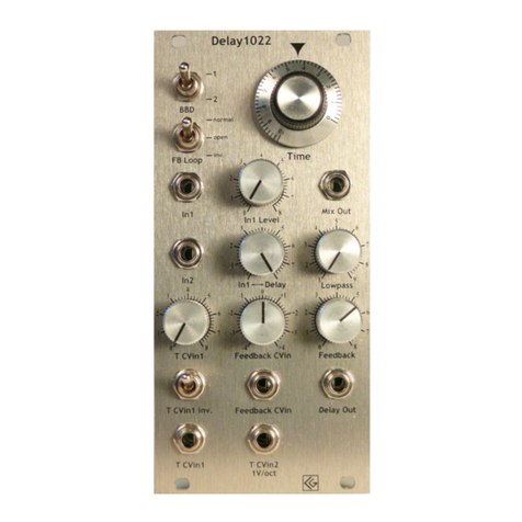
CG Products Delay1022 User manual

Modular
Delay1022
Analog BBD delay
1. Introduction
This module is no classic echo, but a delay designed for audio rate feedback and
sound sculpturing. The 1V/oct. tracking and feedback CV input makes it suitable
for many VCO-like applications, for creating drum and string -like sounds and/or
for room ambience. There is a certain amount of noise, as to be expected from analog D delay
modules, however the Delay1022's clear and brilliant sound in combination with the manually
controllable output low pass filter makes this completely tolerable.
2. Features
–Delay times from 2.5 ms to 50ms (without T CVin)
–CV controllable delay time (≙ feedback frequency)
◦ Good 1V/oct tracking
–Feedback CV control input
–2nd delay output behind feedback-contolling VCA
◦Delay muting
◦Noise reduction
–Manually controllable output lowpass (12d )
◦Noise reduction
◦Sound control
–Available with banana or 3,5mm minijacks
–Eurorack module
–Width: 12 HP
–Dimensions:
128,5 mm x 60,6 mm
–Depth: 52mm
–Supply voltage: ±12V
–Power consumption: ≈ 90mA
Banana jack version Minijack version Drawing
1

Modular
3. Functions
D selector This switch decides if one (512 stages) or two
(1024 stages) Ds ( ucket rigade Device) are used for
delay generation.
Delay Time Manual control of delay time. The range is from
around 1,3ms to 25ms for D switch in upper position
and from ca. 2,5ms to 50ms for the switch in its lower
position (≙ 20-400Hz / 40-760Hz in self-oscillating mode).
This knob adjusts the frequency of the internal D clock
VCO from ≈10kHz to ≈200kHz.
The range can be extended by adding a CV to one of the
respective inputs.
Feedback Loop mode switch In the upper position 'normal',
the delayed signal is routed back to the D's input with its
normal polarity.
(Amount of the back-routed signal depends on the setting of
the poti 'Feedback' and/or a control voltage applied on
'Feedback CVin' )
In middle position 'open', the feedback loop is interrupted.
This allows to insert devices like filters, modulators etc. in
the loop by using the 'In2' input and the 'Delay Out' output
.
In the lower position 'inv.', the delayed signal is inverted and
sent back to the D's input with negative polarity.
Input1 The D's audio signal input. The signal applied on In1 will be mixed with the D's delay
output; the mixed signal is provided on output socket
2 3 456789
21
10 11 13 14 15 16 17 18 19
20 22
12
Objekt in Pfade:
4
4
14
Falsche Zahlen
('Mix out'). The ratio of the mix (dry-
wet) is adjusted with knob ('In1↔ Delay').
In1 Level adjusts the level of the audio signal from In1 .
Mix Output Output signal mix of the D's delayed output and the input signal applied on
'In 1' . The ratio between the two signals (≙ dry-wet) can be adjusted by using knob ('In1↔
Delay') .
Input2 2nd audio signal input for the D. Unlike 'In 1' , this input does not have an input level
and a dry/wet mix control.
2
23456789
21
10 11
12
13 14 15 16 17 18 19
20 22
12
Objekt in Pfade:
4
14
23456789
21
10 11
12
13 14 15 16 17 18 19
20 22
12
Objekt in Pfade:
23456789
21
10 11
12
13 14 15 16 17 18 19
20 22
12
Objekt in Pfade:
23456789
21
10 11
12
13 14 15 16 17 18 19
20 22
12
Objekt in Pfade:
4
23456789
21
10 11
12
13 14 15 16 17 18 19
20 22
12
Objekt in Pfade:
4
2 3 456789
21
10 11
12
13 14 15 16 17 18 19
20 22
12
Objekt in Pfade:
4
23456789
21
10 11
12
13 14 15 16 17 18 19
20 22
12
Objekt in Pfade:
4

Modular
In1↔ Delay Ratio between the signal from input 'In1' and the delayed signal (≙ dry↔wet).
The mixed signal is provided at
23456789
21
10 11 13 14 15 16 17 18 19
20 22
12
Objekt in Pfade:
4
4
14
Falsche Zahlen
.
Lowpass Filter Manual cutoff frequency control for the 12db lowpass filter at the end of the D
stage. This control knob may be useful to reduce noise and for sound control.
Delay Time CV Input 1 manual control for the signal level of a delay time CV (Control Voltage)
signal applied on socket T Cvin 1 .
Feedback CV Input manual control Adjusts the level of feedback CV (Control Voltage) for a
feedback CV signal input applied on socket Feedback CVin .
Feedback: Manual control of feedback. The delay output is fed back into the D input via an
internal VCA (Voltage Controlled Amplifier). The feedback VCA can be manually controlled with
this knob and/or by adding a control voltage to the feedback CV input . From 5-6 on the
scale the delay begins to self-oscillate.
Delay Time CV Inversion Switch Inverts the incoming signal on socket 'T CVin 1' .
Note:
If you are using a delay time CV input (non inverted) for delay time/ frequency modulation,
the feedback sustain may be linearized for different delay times by splitting the T CVin signal
and putting a small amount of this CV into the Feedback CV input. The output level of the Ds
is not constant over the whole delay time range, though the feedback sustain is not linear for
different delay times; e.g., with the same setting of feedback controls, for a short delay time the
tone fades away; while a longer delay time (or lower frequency) will cause a feedback oscillation.
y increasing the feedback level for higher frequencies by adding a proportional CV to this input
this problem can be minimized.
Feedback CV Input Control voltage input for the feedback amplification. Its amount can be
adjusted by using the Feedback CV in knob . A positive input voltage will increase the
feedback; a negative voltage will – in combination with manual control knob 'Feedback' -
attenuate or mute the feedback.
Delay Output This 2nd delay output is behind the internal feedback VCA. Unlike output 'Mix'
2 3 456789
21
10 11 13 14 15 16 17 18 19
20 22
12
Objekt in Pfade:
4
4
14
Falsche Zahlen
,
the output level is directly dependent of the settings of knob 'feedback' and/or the input on
socket 'feedback CV in' ; e.g. if the 'feedback' knob is set on '0' on scale (fully ccw), there
will be no output signal. This muting option can be useful to reduce noise and/or for sound
modelling.
Delay Time CV Input1 Control voltage input for delay time (feedback frequency). Polarity of the
incoming signal can be inverted with 'Inv.' switch ; its amount is adjustable by using poti
'T CVin 1' .
3
23456789
21
10 11
12
13 14 15 16 17 18 19
20 22
12
Objekt in Pfade:
4
23456789
21
10 11
12
13 14 15 16 17 18 19
20 22
12
Objekt in Pfade:
4
2 3 456789
21
10 11
12
13 14 15 16 17 18 19
20 22
12
Objekt in Pfade:
4
23456789
21
10 11
12
13 14 15 16 17 18 19
20 22
12
Objekt in Pfade:
4
23456789
21
10 11
12
13 14 15 16 17 18 19
20 22
12
Objekt in Pfade:
4
23456789
21
10 11
12
13 14 15 16 17 18 19
20 22
12
Objekt in Pfade:
4
23456789
21
10 11
12
13 14 15 16 17 18 19
20 22
12
Objekt in Pfade:
4
2 3 456789
21
10 11
12
13 14 15 16 17 18 19
20 22
12
Objekt in Pfade:
4
2 3 456789
21
10 11
12
13 14 15 16 17 18 19
20 22
12
Objekt in Pfade:
4

Modular
Delay Time 1V/Oct. CV Input 1V/Octave input. The feedback frequency (e.g. in self-oscillating
mode) is a function of the delay time ( Frequency = 1/T) . (It may be necessary to readjust the
tracking. See chapter 4: '
Adjustment
' )
Ground This socket only exists in the
banana
version of the
Delay1022
. The ground connection
is required if the module is connected to external equipment, e.g. a mixer. Within the eurorack
modular system the module is grounded by its power supply.
Audio routing
4
2 3 456789
21
10 11
12
13 14 15 16 17 18 19
20 22
12
Objekt in Pfade:
4
2 3 456789
21
10 11 13 14 15 16 17 18 19
20 22
12
Objekt in Pfade:
4
4
14
Falsche Zahlen
F1/com Pot
F2 Pot
F1 Octave
F2 Octave
F1/com CV ins
F2 CV ins
+
Switch
"com"
FSK in
Switch "FSK"
F1
F2
(without
F1 Octave)
Output
14
F1
F2
BB 1 BB 2
Lowpass
Filter
BB selector
switch
Σ
Mix Out
VCA
Σ
Delay
Out
Σ
Feedback Control
+
_
Feedback
CVin
Feedback
In 2
In 1
In1 elay
In1 Level
Cutoff frequency
_
Feedback loop
switch

Modular
4. Adjustment
The Delay1022's Timebase VCO is already carefully adjusted to 1V/Oct.
If you realize that the Delay1022 isn't in tune with your further analog synthesizer equipment, it could
be necassary to retune it.
Procedure (Suggestion)
1. Switch on your equipment and the Delay1022 and wait ½ hour
until the oscillators have warmed up.
2. Set manual frequency control to ≈ '2' on scale and bring D
selector in upper position.
Turn the 'Lowpass' filter knob fully ccw.
3. Connect a CV from a keyboard (or a similar CV source) both to
your favorite VCO's 1V/oct. input and to the Delay1022's 1V/oct.
input
2 3 456789
21
10 11
12
13 14 15 16 17 18 19
20 22
12
Objekt in Pfade:
4
.
(You can also use the us CV; to activate the Delay1022's us CV
input see chapter5: '
us CV
')
4. Connect both devices, your favorite VCO and the Delay1022, to a
sound system, that you can listen to them simultaneously.
5. ring the Delay1022 in self-oscillating mode by turning knob
'Feedback' clockwise.
6. Play a 'C' (65,41Hz), or a similar note, on your keyboard . The VCO should be in pitch with the
keyboard. The note should be nearby the tone you have adjusted on the Delay1022.
7. Adjust poti 'Time' until the pitch of the Delay1022 is the same as that of the 2nd VCO.
8. Play a note ≈ 2-3 octaves higher (e.g. c2, ≙523,3Hz). Adjust trimmer Tr1 on the back of the
module (see above) until the Delay1022 is tracking to the 2nd VCO.
9. Go back to step "6" and repeat all other steps until both devices are in tune.
5. Bus CV
Jumper "JP1" in "off" position (PC ): The us CV is
not connected.
Jumper "JP1" in "on" position (PC side): The us
CV is controlling the Delay1022's delay time.
5

Modular
5. Patc Templates
Note your own patch ideas "
Temp ate Height: 70mm
6. Contact & Support
Christian Günther
Forster Str. 50
10999 Ber in
Phone: ++49 30 61286299
Mobi e ++49 178 7699267
www.cg-products.de
The 10 HP (previous) version see under http://www.cg-products.de/Delay1022-10HP_documentation.pdf
© Christian Günther Nov2014
6
Table of contents
Other CG Products Control Unit manuals
Popular Control Unit manuals by other brands
Ebsray
Ebsray RV Series Installation, operation & maintenance instructions
Greystone Energy Systems
Greystone Energy Systems GT-AI-420 Series installation instructions

Ziton
Ziton ZP3-ECU Installation and commissioning manual
ABB
ABB ACSM1 Series Hardware manual
Dormakaba
Dormakaba ED connection board CAN Assembly instruction
NextLight
NextLight Pro Series user manual
