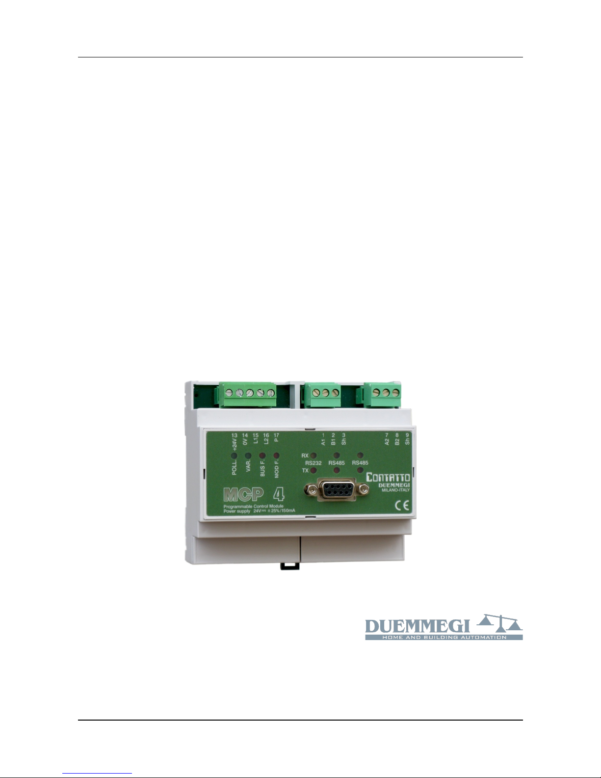
Contatto MCP 4 – User's manual DUEMMEGI
INDEX
A1- LIST OF REVISIONS OF THIS MANUAL..............................................................................................................4
A2- RECOMMENDATIONS..........................................................................................................................................4
A3- NEWS OF MCP 4 AGAINST MCP XT AND AVAILABLE VERSIONS..................................................................5
1- MAIN FEATURES.....................................................................................................................................................6
1.1- Required Hardware and Software tools...........................................................................................................6
1.2- Main features of MCP 4....................................................................................................................................6
1.3- Terminology and syntax...................................................................................................................................7
2- EQUATIONS: TYPES AND SYNTAX.......................................................................................................................
2.1- Equations for the system configuration............................................................................................................
2.1.1- Configuration of the modules.............................................................................................................
2.1.2- Power ON status................................................................................................................................
2.1.3- Status of fault input modules..............................................................................................................
2.1.4- Communication Protocol....................................................................................................................9
2.1.5- Address of MCP 4............................................................................................................................11
2.1.6- Identifier of MCP 4............................................................................................................................11
2.1.7- Directive for the calculation of sunrise, sunset and sun position.....................................................11
2.1. - Publishing on the bus the status of virtual points and value of registers........................................12
2.1.9- Management of fault modules..........................................................................................................12
2.1.10- Alignment of the outputs.................................................................................................................12
2.1.11- Data exchange between MCP 4 controllers...................................................................................13
2.1.12- Number of nodes in a MCP 4 network...........................................................................................15
2.1.13- Scheduler........................................................................................................................................16
2.2- Event triggered Equations..............................................................................................................................17
2.2.1- Logic equations................................................................................................................................17
2.2.2- SET – RESET equations..................................................................................................................17
2.2.3- TOGGLE equations..........................................................................................................................1
2.2.4- COUNTER Equations.......................................................................................................................1
2.2.5- THRESHOLD Equations..................................................................................................................20
2.2.6- TIMER Equations.............................................................................................................................20
2.2.7- Equations for mathematical and logic calculation............................................................................21
2.2. - Equations for binary code generation..............................................................................................22
2.2.9- Equations for recording status changes (EVENT)...........................................................................23
2.2.10- Equations for recording value changes (LOG)...............................................................................24
2.2.11- Management of the external counter modules (ModCNT).............................................................25
2.2.12- Management of DALI module (ModDALI)......................................................................................25
2.3- Time triggered Equations...............................................................................................................................27
2.3.1- Scheduler Equations........................................................................................................................27
2.4- Macro..............................................................................................................................................................29
3- SCRIPT...................................................................................................................................................................31
3.1- Summary.........................................................................................................................................................31
3.2- Keywords and syntax.....................................................................................................................................32
3.2.1- Using the TRIGGER.........................................................................................................................32
3.2.2- VAR, GLOBAL VAR and EXTERN VAR..........................................................................................33
3.2.3- Logic and Mathematical operations.................................................................................................33
3.2.4- IF…THEN…ELSE…ENDIF..............................................................................................................34
3.2.5- CARRY and ZERO...........................................................................................................................35
3.2.6- DEFINE.............................................................................................................................................35
3.2.7- GOTO...............................................................................................................................................37
3.2. - SUBROUTINES and FUNCTIONS..................................................................................................37
3.2.9- BIT(x)................................................................................................................................................40
3.2.10- WORD(x) and pointers...................................................................................................................42
Page 2 of 7 Rel.: 1.2 October 201 DUEMMEGI s.r.l. - Via Longhena, 4 – 20139 MILANO
Tel. 02/57300377 - Fax 02/552136 6 – www.duemmegi.it