CG Products Delay1022 User manual
Modular
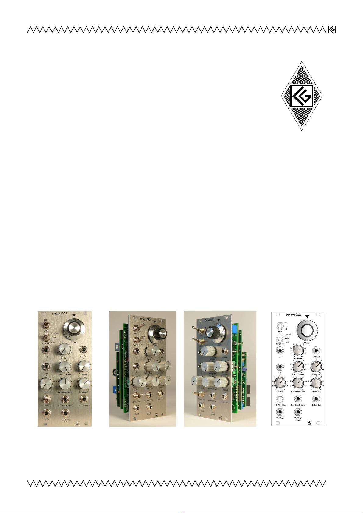
Delay1022
Analog BBD delay
1. Introduction
This module is no classic echo, but a delay designed for audio rate feedback and
sound sculpturing. The 1V/oct. tracking and feedback CV input makes it suitable
for many VCO-like applications, for creating drum and string -like sounds and/or
for room ambience. There is a certain amount of noise, as to be expected from analog D delay
modules, however the Delay1022's clear and brilliant sound in combination with the manually
controllable output low pass filter makes this completely tolerable.
2. Features
–Delay times from 2.5 ms to 50ms (without T CVin)
–CV controllable delay time (≙ feedback frequency)
◦ Good 1V/oct tracking
–Feedback CV control input
–2nd delay output behind feedback-contolling VCA
◦Delay muting
◦Noise reduction
–Manually controllable output lowpass (12d )
◦Noise reduction
◦Sound control
–Available with banana or 3,5mm minijacks
–Eurorack module
–Width: 12 HP
–Dimensions:
128,5 mm x 60,6 mm
–Depth: 52mm
–Supply voltage: ±12V
–Power consumption: ≈ 90mA
Front view Left side view Right side view Drawing
1

Modular
3. Functions
D selector This switch decides if one (512 stages) or two
(1024 stages) Ds ( ucket rigade Device) are used for
delay generation.
Delay Time Manual control of delay time. The range is from
around 25ms to 1,3ms for D switch in upper position
and from ca. 50ms to 2,5ms for the switch in its lower
position (≙ 20-400Hz / 40-760Hz in self-oscillating mode).
This knob adjusts the frequency of the internal D clock
VCO from ≈10kHz to ≈200kHz.
The range can be extended by adding a CV to one of the
respective inputs.
Feedback Loop mode switch In the upper position 'normal',
the delayed signal is routed back to the D's input with its
normal polarity.
(Amount of the back-routed signal depends on the setting
of the poti 'Feedback' and/or a control voltage applied on
'Feedback CVin' )
In middle position 'open', the feedback loop is interrupted.
This allows to insert devices like filters, modulators etc. in
the loop by using the 'In2' input and the 'Delay Out'
output .
In the lower position 'inv.', the delayed signal is inverted
and sent back to the D's input with negative polarity.
Input1 The D's audio signal input. The signal applied on In1 will be mixed with the D's delay
output; the mixed signal is provided on output socket
2 3 456789
21
10 11 13 14 15 16 17 18 19
20 22
12
O jekt in Pfade:
4
4
14
Falsche Zahlen
('Mix out'). The ratio of the mix (dry-wet)
is adjusted with knob ('In1↔ Delay').
In1 Level adjusts the level of the audio signal from In1 feeding the Ds.
Mix Output Output signal mix of the D's delayed output and the input signal applied on
'In 1' . The ratio between the two signals (≙ dry-wet) can be adjusted by using knob ('In1↔
Delay') .
Input2 2nd audio signal input for the D. Unlike 'In 1' , this input does not have an input level
and a dry/wet mix control.
In1↔ Delay Ratio between the signal from input 'In1' and the delayed signal (≙ dry↔wet). The
mixed signal is provided at
2 3 456789
21
10 11 13 14 15 16 17 18 19
20 22
12
O jekt in Pfade:
4
4
14
Falsche Zahlen
.
2
23456789
21
10 11
12
13 14 15 16 17 18 19
20 22
12
O jekt in Pfade:
23456789
21
10 11
12
13 14 15 16 17 18 19
20 22
12
O jekt in Pfade:
23456789
21
10 11
12
13 14 15 16 17 18 19
20 22
12
O jekt in Pfade:
23456789
21
10 11
12
13 14 15 16 17 18 19
20 22
12
O jekt in Pfade:
4
23456789
21
10 11
12
13 14 15 16 17 18 19
20 22
12
O jekt in Pfade:
4
2 3 456789
21
10 11
12
13 14 15 16 17 18 19
20 22
12
O jekt in Pfade:
4
23456789
21
10 11
12
13 14 15 16 17 18 19
20 22
12
O jekt in Pfade:
4
23456789
21
10 11
12
13 14 15 16 17 18 19
20 22
12
O jekt in Pfade:
4
Modular
Lowpass Filter Manual cutoff frequency control for the 12db lowpass filter at the end of the D
stage. This control knob may be useful to reduce noise and for sound control.
Note:
The lowpass filter is also affecting the 1V/oct. behaviour of the delay. y default, the 1V/oct.
tracking is best matched for a value of ≈3-4 on scale of the lowpass filter knob.
Delay Time CV Input 1 manual control for the signal level of a delay time CV (Control Voltage)
signal applied on socket T Cvin 1 .
Feedback CV Input manual control (Polarizer) Adjusts the level of feedback CV (Control Voltage)
for a feedback CV signal input applied on socket Feedback CVin . In center position (denter
locked) the input level is 0. Turning this knob clockwise, the incoming feedback CV signal will be
normally added to the feedback control signal adjusted with knob . y turning the knob ccw, the
polarity of the CV signal becomes inverted resulting in a substraction/attenuation of the feedback
control voltage.
Feedback: Manual control of feedback. The delay output is fed back into the D input via an
internal VCA (Voltage Controlled Amplifier). The feedback VCA can be manually controlled with this
knob and/or by adding a control voltage to the feedback CV input . From 5-6 on the scale the
delay is beginning to self-oscillate.
Delay Time CV Inversion Switch Inverts the incoming signal on socket 'T CVin 1' .
Feedback CV Input Control voltage input for the feedback amplification. Its amount and polarity
can be adjusted by using the Feedback CV in knob . A positive voltage will increase the
feedback; a negative voltage will attenuate or mute the feedback.
Delay Output This 2nd delay output is behind the internal feedback VCA. Unlike output 'Mix'
2 3 456789
21
10 11 13 14 15 16 17 18 19
20 22
12
O jekt in Pfade:
4
4
14
Falsche Zahlen
, the
output level is directly dependent of the settings of knob 'feedback' and/or the input on socket
'feedback CV in' ; e.g. if the 'feedback' knob is set on '0' on scale (fully ccw), there will be no
output signal. This muting option can be useful to reduce noise and/or for sound modelling. This
output may also be used – together with input 'In 2' - to insert filters etc. into the feedback loop.
Delay Time CV Input1 Control voltage input for delay time (feedback frequency). Polarity of the
incoming signal can be inverted with 'Inv.' switch ; its amount is adjustable by using knob
'T CVin 1' .
Delay Time 1V/Oct. CV Input 1V/Octave input. The feedback frequency (e.g. in self-oscillating
mode) is a function of the delay time ( Frequency = 1/T) .
Note:
The 1V/oct. tracking is also a little bit dependent of the lowpass filter setting.
For 1V/oct. adjustment, see chapter '
4.
1V/Oct. Adjustment
'
3
23456789
21
10 11
12
13 14 15 16 17 18 19
20 22
12
O jekt in Pfade:
4
2 3 456789
21
10 11
12
13 14 15 16 17 18 19
20 22
12
O jekt in Pfade:
4
23456789
21
10 11
12
13 14 15 16 17 18 19
20 22
12
O jekt in Pfade:
4
23456789
21
10 11
12
13 14 15 16 17 18 19
20 22
12
O jekt in Pfade:
4
2 3 456789
21
10 11
12
13 14 15 16 17 18 19
20 22
12
O jekt in Pfade:
4
2 3 456789
21
10 11
12
13 14 15 16 17 18 19
20 22
12
O jekt in Pfade:
4
2 3 456789
21
10 11
12
13 14 15 16 17 18 19
20 22
12
O jekt in Pfade:
4
23456789
21
10 11
12
13 14 15 16 17 18 19
20 22
12
O jekt in Pfade:
4
23456789
21
10 11
12
13 14 15 16 17 18 19
20 22
12
O jekt in Pfade:
4
Modular
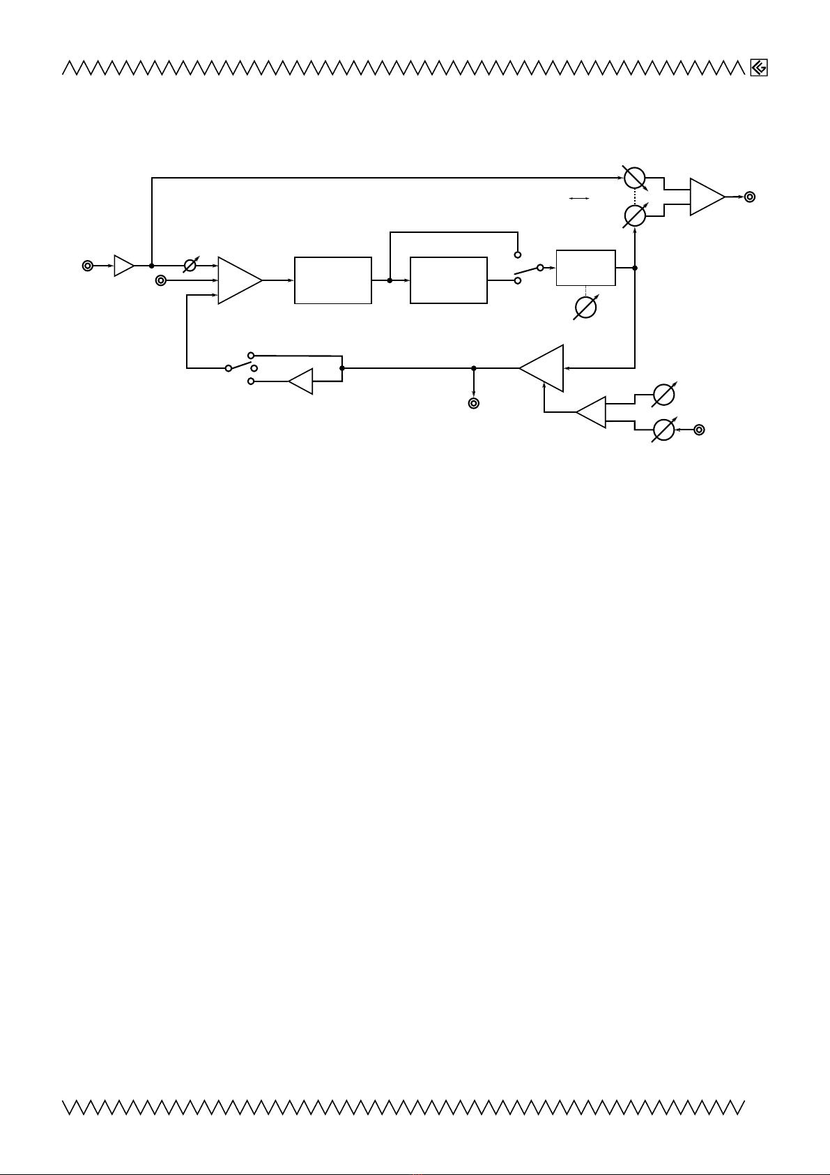
Audio routing
4
F1/com Pot
F2 Pot
F1 Octave
F2 Octave
F1/com CV ins
F2 CV ins
+
Switch
"com"
FSK in
Switch "FSK"
F1
F2
(without
F1 Octave)
Output
14
F1
F2
BB 1 BB 2
Lowpass
Filter
BB selector
switch
Σ
Mix Out
VCA
Σ
Delay
Out
Σ
Feedback Control
+
_
Feedback
CVin
Feedback
In 2
In 1
In1 elay
In1 Level
Cutoff frequency
_
Feedback loop
switch
Modular
4. 1V/Oct. Adjustment
The Delay1022's Timebase VCO is already carefully adjusted to 1V/oct.
If you realize that the Delay1022 isn't in tune with your further analog synthesizer equipment, it could
be necassary to retune it.
Procedure (Suggestion)
1. Switch on your equipment and the Delay1022 and wait ½
hour until the oscillators have warmed up.
2. Set manual frequency control to ≈ '2' on scale and bring
D selector in upper position.
Turn the 'Lowpass' filter knob to ≈ 3-4 on scale (the
lowpass filter is affecting the 1V/oct. behaviour; if you
prefer another default filter setting for best 1V/oct.
tracking, than you may change the lowpass filter setting for
this adjustment procedure).
3. Connect a CV from a keyboard (or a similar CV source) both
to your favorite VCO's 1V/oct. input and to the Delay1022's
1V/oct. input
2 3 456789
21
10 11
12
13 14 15 16 17 18 19
20 22
12
O jekt in Pfade:
4
.
(You can also use the us CV; to activate the Delay1022's
us CV input see chapter5: '
us CV
')
4. Connect both devices, your favorite VCO and the Delay1022, to a sound system, that you can
listen to them simultaneously.
5. ring the Delay1022 in self-oscillating mode by turning knob 'Feedback' fully clockwise.
6. Play a 'C' (65,41Hz), or a similar note, on your keyboard . The VCO should be in pitch with the
keyboard. The note should be nearby the tone you have adjusted on the Delay1022.
7. Adjust poti 'Time' until the pitch of the Delay1022 is the same as that of the 2nd VCO.
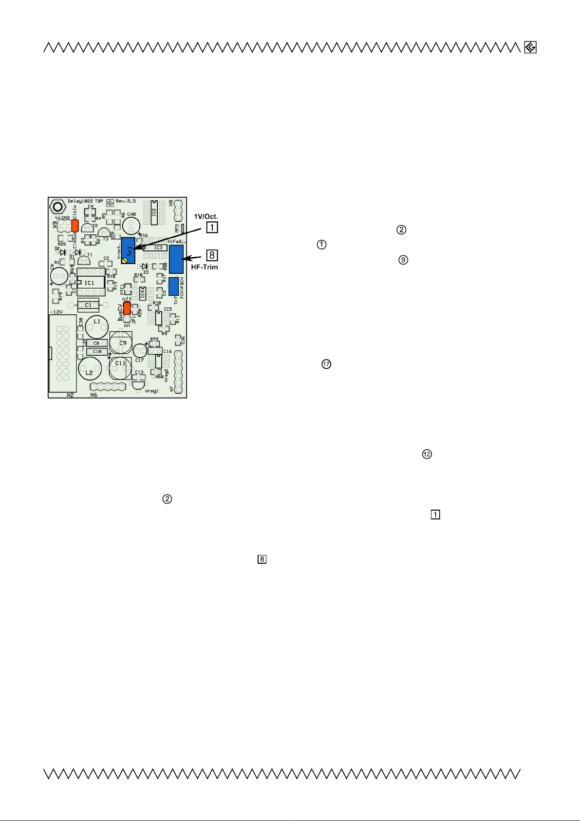
8. Play a note ≈ 2-3 octaves higher (e.g. c2, ≙523,3 Hz). Adjust trimmer Tr1
2 3 456789
21
10 11 13 14 15 16 17 18 19
20 22
12
O jekt in Pfade:
4
4
14
Falsche Zahlen
4
on the back of the
module (see above) until the Delay1022 is tracking to the 2nd VCO (zero-beat).
9. Play a note 1 octave higher than in step 8, e.g. 1046,6 Hz (3-4 octaves higher than the ground
note). If necessary, adjust HF trimmer
23456789
21
10 11 13 14 15 16 17 18 19
20 22
12
O jekt in Pfade:
4
4
14
Falsche Zahlen
48
until both tones are tracking (zero-beat).
10. Go back to step "6" and repeat all other steps until both devices are in tune.
5
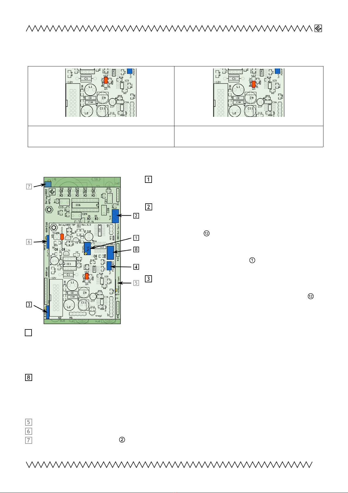
Modular
5. Bus V
Jumper "JP1" up = „off“ position (PC side): The
us CV is not connected.
Jumper "JP1" down = "on" position (PC side): The
us CV is controlling the Delay1022's delay time.
6. Further Adjustments
23456789
21
10 11 13 14 15 16 17 18 19
20 22
12
O jekt in Pfade:
4
4
14
Falsche Zahlen
4
1V/Oct. Adjustment
See above:
4. 1V/Oct. Adjustment
D1 output attenuator
(Feedback insertion point)
Output attenuator for D1; due to the position of
knob 'Feedback' , ensuring the same amplitude and
feedback level for D1 in relationship to D2 and to
avoid upcoming self-oscillation when switching
between D1 and D2 (switch ).
23456789
21
10 11 13 14 15 16 17 18 19
20 22
12
O jekt in Pfade:
4
4
14
Falsche Zahlen
4
VCA operating point
The setting of this trimmer determines the VCA's
working point – at which position of knob 'Feedback'
the delay will begin to self-oscillate; by default this
point is set on 5-6 on the scale (2 o'clock).
23456789
21
10 11 13 14 15 16 17 18 19
20 22
12
O jekt in Pfade:
4
4
14
Falsche Zahlen
4
Feedback compensation for short delay times
For short delay times, the audio signal gets more attenuated – causing a shorter feedback for
short delay times. To avoid this, this effect is internally compensated. Value of compensation is
set by this trimmer.
HF-Trim
See above:
4. 1V/Oct. Adjustment
For completeness - however these settings should not be changed:
23456789
21
10 11 13 14 15 16 17 18 19
20 22
12
O jekt in Pfade:
4
4
14
Falsche Zahlen
48
VCA output offset
23456789
21
10 11 13 14 15 16 17 18 19
20 22
12
O jekt in Pfade:
4
4
14
Falsche Zahlen
48
D chips input bias
23456789
21
10 11 13 14 15 16 17 18 19
20 22
12
O jekt in Pfade:
4
4
14
Falsche Zahlen
48
Feedback time potentiometer range
6
23456789
21
10 11 13 14 15 16 17 18 19
20 22
12
O jekt in Pfade:
4
4
14
Falsche Zahlen
4
23456789
21
10 11 13 14 15 16 17 18 19
20 22
12
O jekt in Pfade:
4
4
14
Falsche Zahlen
48
Modular
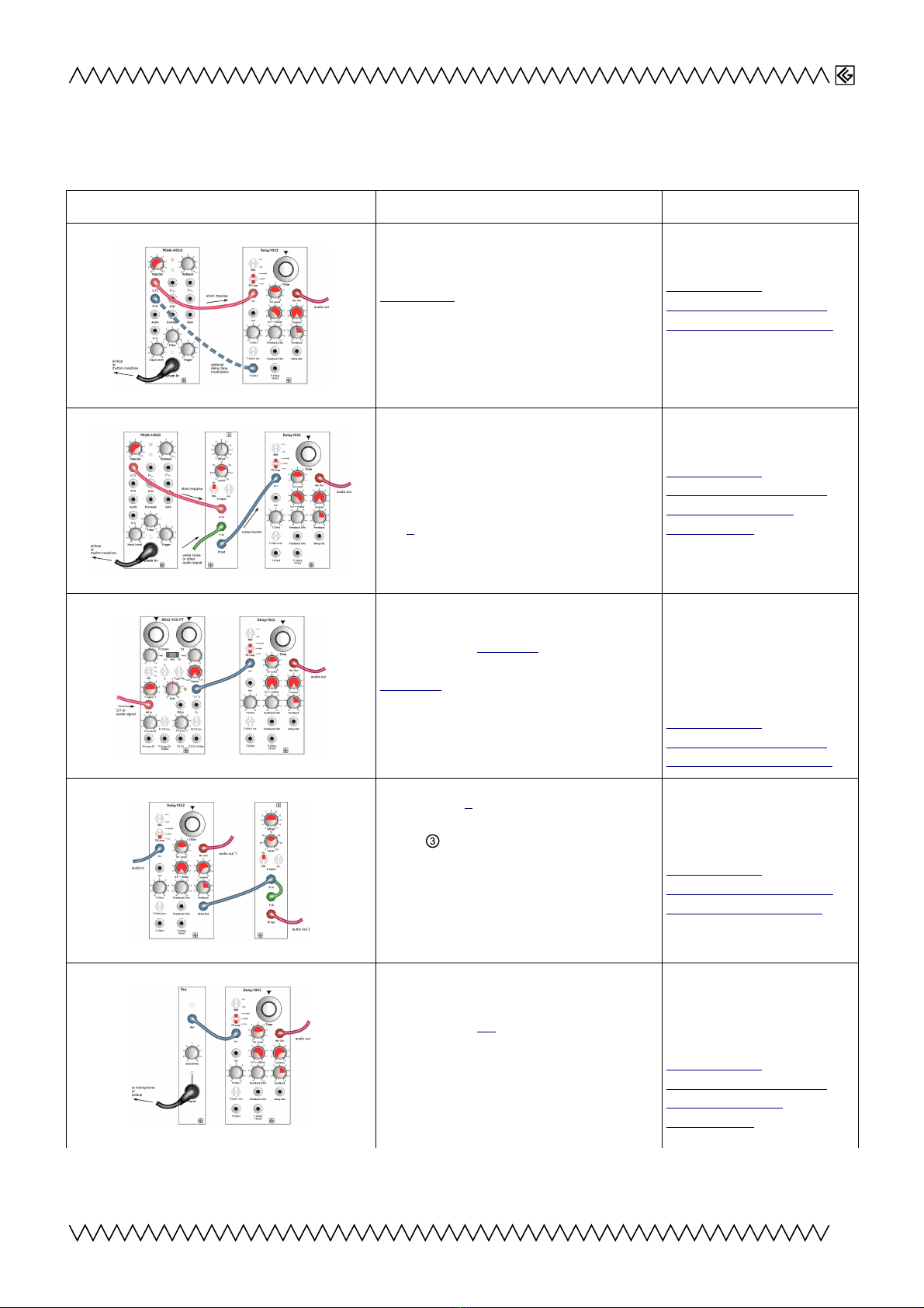
7.Patches
Simple patches (with other CG Products' modules)
Patch Description Audio Link
1. Delay1022 triggered with short impulses
The dynamic pulse output of the
PEAK+HOLD (or any other impulse source)
feeding the Delay1022 is a simple way to
create percussive drum and string-like
sounds.
http://www.cg-
products.de/Audio/Delay-
Patch1_ImpulseIn-350.mp3
2. Delay1022 triggered with noise-bursts
etter, because allowing more dynamic range
and more sound options, is using short
noise-bursts or another short envelope-
shaped sound source to trigger the delay.
The X multiplier in this example is working as
a linear VCA.
http://www.cg-
products.de/Audio/Delay-
Patch2_X-ImpulseIn-
355+357.mp3
3. Delay1022 & XR22 VCO
The combination of the Delay1022 with the
XR22 VCO opens up a wide variety of
fascinating sounds.
XR22 VCO AM in:
Rhythm machine;
XR22 VCO frequency
modulated with PEAK+HOLD;
Delay time modulated with
sequencer & 2nd VCO:
http://www.cg-
products.de/Audio/Delay-
Patch3_XR22VCO-364.mp3
4. Delay1022 X modulated
With the delay's F loop in inversion mode
(Switch in lower position 'inv') and the
delay's output amplitude-modulated with
itself, a 2nd 'voice' with interesting timbres
and exponential dynamic can be produced,
useful e.g. in stereo applications.
Delay In: Rhythm machine
http://www.cg-
products.de//Audio/Delay-
Patch4_outputX-367.mp3
5. Delay1022 & Pre
Embed acoustic instruments and sounds via
microphone or pickup.
Delay effects, flanging, phasing etc.
PRE In: Microphone/Trumpet
...Delay time modulation with
sinewave
http://www.cg-
products.de/Audio/Delay-
Patch5_Pre-trump-
377+378.mp3
7

Modular
8. ontact & Support
Christian Günther
Forster Str. 50
10999 Berlin
www.cg-products.de
Phone: ++49 30 61286299
Mo ile ++49 178 7699267
Product we page: https://www.cg-products.de/module/delay1022/
This is Revision 5.5
Documentations for previous versions see here:
https://www.cg-products.de//documentations/Delay1022_documentation_Rev.4.pdf
https://www.cg-products.de//documentations/Delay1022_documentation_Rev. .pdf
https://www.cg-products.de/documentations/Delay1022_documentation_Rev.2.pdf
https://www.cg-products.de/documentations/Delay1022_documentation_Rev.1.pdf
© Christian Günther 2021
8
Table of contents
Other CG Products Control Unit manuals

Popular Control Unit manuals by other brands

SPX FLOW
SPX FLOW Delair Etsiline CommPact manual

HydroQuip
HydroQuip Baja Sportub ECO-5/6100 Series troubleshooting guide

Delta
Delta R3270-MIXLF quick start guide

Keyautomation
Keyautomation CT-724S Instructions and warnings for installation and use

SIGMA TEK
SIGMA TEK AI 047 instruction manual

Glowworm
Glowworm Climapro2 RF Instructions for use

Abus
Abus FUMO50110 Installation instructions and user guide

SPX FLOW
SPX FLOW Waukesha Cherry-Burrell DA4 instruction manual

USR IOT
USR IOT USR-K6 user manual

SPX FLOW
SPX FLOW APV DELTA SI2 instruction manual

Murrelektronik
Murrelektronik Data Panel xtreme DB DP-34044-1 user manual

WHISPER KOOL
WHISPER KOOL Ceiling Mount 8000 manual


