CG Products XR1-E User manual

XR1-E
Ring Modulation Oscillator
The
XR1-E
is an analog ring modulator desktop device with internal oscillator, preamp and LFO
in a nice hand-made casing
It offers a wide variety of sounds, from the typical ringmodulation- and tremolo-like sounds to
glissando- and random-like patterns or distortion
An integrated low-noise preamp (with much headroom) allows to adapt any kind of input
sources like microphones, e-guitars or electronic instruments
A bicolor LED offers optical control of the oscillator's and preamp's overdrive behaviour
The oscillator frequency is manually adjustable with two knobs for coarse and fine tuning and a switch for high and low
(tremolo) range An envelope follower, a LFO and a Sample+Hold is provided for frequency modulation; further, there is a
minijack 1V/oct input for control by e g an external synthesizer and another frequency control input for e g a pedal
The
XR1-E
also offers a footswitch input socket to apply an external footswitch (not included) for switching between the
effect and the original The
XR1-E
works with
true bypass
routing
Further, the output level of the processed signal can be
aligned by a knob on the rear
Due to the ability of battery operation the device is independent from external power supply, but there is also a socket
for external DC (6-15V)
The
XR1-E
is based on a function generator chip, which warm and smooth sound makes it excellently suitable for ring
modulation and electronic music
Low noise preamp
Bicolor LED for visual control
Frequency modulation with envelope follower, LFO and/or Sample+Hold
1V/oct minijack input and 2nd input for external frequency control
Footswitch input – true bypass
Output gain adjustable
Battery (6x AA) or with external DC operatable
Unique handmade casing
1

Quick start guide
1 Insert batteries or accus (6x AA Mignon) or connect a power adaptor (DC 9-16V, +-
pole: the outer side of the plug) Set the power switch upwards to "On" Connect an
amplifier, mixer etc to the output and connect an instrument or microphone to the
instrument input
2 Turn the knobs 'Output Gain' and 'AM in Drive' on the backside in ≈middle position
3 Set the frequency selector switch on "Hi" Turn the bypass pot in fully right
position : "100%" and the envelope and LFO modulation knobs and in fully left
position: "0" Move knob 'Carrier Surpression' in middle position = "0" on the scale/
denter locked; watch the LED
23456789
21
10 11 13 14 15 16 17 18 19
20 22
12
Objekt in Pfade:
4
4
14
Falsche Zahlen
48
9
10
11
12
23
for indication)
Adjust the "Preamp" input gain controller while playing your instrument and listen
for optimal performance Watch LED
23456789
21
10 11 13 14 15 16 17 18 19
20 22
12
Objekt in Pfade:
4
4
14
Falsche Zahlen
48
9
10
11
12
23
- it should even not light red
4 When using an external footswitch for dry/wet control, adjust 'Output Gain' Trimmer
for same output amplitude of the effect and the original signal
2

Functions
On/Off Switch
Switches the power supply on or off
Note: In combination with an external power adaptor only the XR1-E will be switched off and
not
the power adaptor itself
External Power Supply Input
For operation of the
XR1-E
with an external DC power adaptor The connection is a standard DC
plug with 2 1mm diameter hole The "+"pole is the outer contact, which is almost common for
effect pedals etc The internal batteries will be switched off when this socket is in use The input
voltage range is 6V – 15V Typical current dissipation at 9V: ≈ 140mA
Output
For connecting the
XR1-E
to an amplifier, mixer or another following stage
The output level is adjustable with the trimpot 'Output Gain' on the rear
Maximum output voltage is ≈ 8Vpp (Knobs and 'AM In Drive'
23456789
21
10 11 13 14 15 16 17 18 19
20 22
12
Objekt in Pfade:
4
4
14
Falsche Zahlen
4
fully turned up)
When using a footswitch applied on and the oscillator is shut off (or if the
XR1-E
is switched
off), the output provides directly the original signal applied on instrument input ('
true bypass
' –
the signal it is not flowing through any electronic circuit when bypassed)
Output Gain
This knob (on the back) controls the final amplification provided on output When using an
external footswitch inserted to ('Footswitch'), this allows to align the effect signal to the dry
input signal Further it may be useful if you need some extra amplification
Instrument Input
Input jack for instrument or microphone Max input voltage without distortion: ≤8Vpp;
impedance: ca 600kΩ.
Preamp Gain Control
Input level control for the instrument input preamp, which is sourcing the oscillator's amplitude
modulation input The preamp is also able to process larger input levels (such as coming from
electronic instruments) The bicolor LED
23456789
21
10 11 13 14 15 16 17 18 19
20 22
12
Objekt in Pfade:
4
4
14
Falsche Zahlen
48
9
10
11
12
23
signalizes - when lighting red - when the preamp is
becoming overdriven For best signal-to-noise ratio the level should be even below the point when
the LED is lighting red The preamp shows soft clipping behaviour
Carrier Surpression Control
For 'normal' operation, this knob is turned to its middle position (denter locked, '0' on scale) When
turning it right or left, the oscillator's tone will appear This may be used for special sound effects;
furthermore when using a very low frequency input signal (such as e g pulse patterns), the
adjusting may influence the sound behaviour
Note:
There will always remain a little bit of the oscillator sound (2nd harmonics etc ) For best
performance, make sure that the input signal level is high
3
23456789
21
10 11
12
13 14 15 16 17 18 19
20 22
12
Objekt in Pfade:
23456789
21
10 11
12
13 14 15 16 17 18 19
20 22
12
Objekt in Pfade:
23456789
21
10 11
12
13 14 15 16 17 18 19
20 22
12
Objekt in Pfade:
23456789
21
10 11
12
13 14 15 16 17 18 19
20 22
12
Objekt in Pfade:
4
2 3 456789
21
10 11
12
13 14 15 16 17 18 19
20 22
12
Objekt in Pfade:
4
23456789
21
10 11
12
13 14 15 16 17 18 19
20 22
12
Objekt in Pfade:
4
23456789
21
10 11
12
13 14 15 16 17 18 19
20 22
12
Objekt in Pfade:
4

Bypass
This 'dry/wet' control knob is changing the ratio between input signal (preamplified) and the ring
modulated effect signal Turning the knob fully left will provide only the preamplified input signal;
by turning the knob clockwise the effect will be mixed with original Fully right position = "100%":
the pure ring modulation effect signal
Footswitch Input
An external 2pole footswitch (not included) can be applied
•Switch closed: The dry original input signal (
true bypass
)
•Switch opened: The effect signal (also depending on postion of the "Bypass" control knob )
The switching is also controllable by an external logic signal (0V = effect , +5V = dry), e g a gate
signal from a synthesizer
To align the output amplitudes of the dry and wet signal, adjust the output signal with 'Output
Gain' trimmer
Oscillator Frequency Hi h/Low Switch
Hi: ≈ 8Hz – 18000 Hz (Audio range)
Lo: ≈ 0,15Hz – 100 Hz (Tremolo)
In "Hi" position, the oscillator is mainly working in audio range The amplitude modulation will
generate additional audio frequencies – sum and difference tones of the input signal and the
oscillator frequency
In "Lo" position, the oscillator is working with subaudio frequencies The amplitude modulation
result is a tremolo-like sound Volume of the input signal will change constantly with the
oscillator frequency
Oscillator Frequency Control
Coarse adjustment of the amplitude modulation (AM) oscillator frequency
Oscillator Frequency Fine Adjustment Control
Fine tuning of the oscillation frequency Range is about 4 – 5 semitones (quarte)
Oscillator Waveform Switch
The ring modulator oscillator waveform can be selected between sinewave and triangle In " "
(sine) position, the effect is a more smooth sound with less overtones; in " " (triangle) mode the
generated sounds are rougher and with more overtones Knob 'AM In Drive'
23456789
21
10 11 13 14 15 16 17 18 19
20 22
12
Objekt in Pfade:
4
4
14
Falsche Zahlen
4
(on the rear) also
affects the behaviour of these modulations
LFO Frequency Control
Speed control of the internal LFO (low frequency oscillator) for frequency modulation of the ring
modulation oscillator Frequency is from ≈0 06Hz (left position ) to ≈ 44Hz (right position)
The LFO frequency is also displayed by the orange LED for visual control
LFO Modulation Depth Control
Adjusts the LFO modulation depth
4
23456789
21
10 11
12
13 14 15 16 17 18 19
20 22
12
Objekt in Pfade:
4
23456789
21
10 11
12
13 14 15 16 17 18 19
20 22
12
Objekt in Pfade:
4
2 3 456789
21
10 11
12
13 14 15 16 17 18 19
20 22
12
Objekt in Pfade:
4
23456789
21
10 11
12
13 14 15 16 17 18 19
20 22
12
Objekt in Pfade:
4
23456789
21
10 11
12
13 14 15 16 17 18 19
20 22
12
Objekt in Pfade:
4
2 3 456789
21
10 11
12
13 14 15 16 17 18 19
20 22
12
Objekt in Pfade:
4
2 3 456789
21
10 11
12
13 14 15 16 17 18 19
20 22
12
Objekt in Pfade:
4
2 3 456789
21
10 11
12
13 14 15 16 17 18 19
20 22
12
Objekt in Pfade:
4

LFO Waveform Switch
The LFO waveform is selectable between triangle (" ") and squarewave (" ") " " will provide a
continously up-and down gliding pitch, while " " makes the oscillator shifting between two
tones
Envelope Follower/Sample+Hold/ext. CV Modulation Depth Control
The internal envelope follower converts the volume of the audio signal on the instrument input
into a control voltage, which then is used for modulating the oscillator frequency
Switch
S+H'
in upper
position
The preamplified
audio signal
The generated
envelope signal for
frequency
modulation
With switch 'S+H' in upper position, the amount of the envelope modulation is adjustable by
this knob ( Or alternatively, the amount of Sample+Hold modulation can be adjusted, depending
on the position of switch 'S+H'; please read the refering point )
If the external frequency CV (= Control Voltage) input is used, the internal envelope follower
will be switched off and replaced by the signal applied on - e g from a pedal (or the respective
S+H modulation)
Envelope Follower/Sample+Hold/ext. CV Modulation Inversion Switch
Switches the modulation polarity (from the envelope follower, Sample+Hold or an external source
on ) from positive to negative If the switch is in upper position, the pitch of the AM oscillator
will increase with higher voltage of the modulation signal With the switch in lower position 'Inv'
(="Inversion") the pitch will decrease with higher input voltage The inversion switch works also for
a control voltage signal connected to
External Frequency Control Input
Allows to control the oscillator pitch by an external control voltage (CV) or an external resistor By
connecting a jack to this input, the internal envelope follower/S+H will be shut off and instead the
applied control voltage will modulate the oscillator's frequency (with switch 'S+H' in upper
position); the modulation depth can be adjusted by knob ; the modulation CV's polarity can be
inverted by switch
Further, a +5V DC voltage (via 10kΩ resistor) is provided on , available on the middle connector
of a 3pole jack plugged in Thus may
be useful, for example, in combination
with a sensor or a pedal In the latter
case, a common passive foot pedal with
3pole jack should work
5
23456789
21
10 11
12
13 14 15 16 17 18 19
20 22
12
Objekt in Pfade:
4
2 3 456789
21
10 11
12
13 14 15 16 17 18 19
20 22
12
Objekt in Pfade:
4
23456789
21
10 11 13 14 15 16 17 18 19
20 22
12
Objekt in Pfade:
4
4
14
Falsche Zahlen
4
23456789
21
10 11 13 14 15 16 17 18 19
20 22
12
Objekt in Pfade:
4
4
14
Falsche Zahlen
4

When using the Sample+Hold (switch 'S+H' in middle or lower position), the external signal will
replace the envelope follower's voltage and this external signal in combination with the LFO
will be processed by the Sample+Hold; please read the following point
S+H Sample+Hold switch (new from Rev.4)
Alternatively to the modulation with the envelope shape (with switch in upper position 'off'), an
Sample+Hold circuit can be activated for frequency modulation (switch in middle or lower
position)
A Sample+Hold circuit consists of two inputs, an analog voltage input and a clock input, and an
output providing the generated Sample+Hold voltage Each time when the clock signal is
activating the S+H, the S+H is reading the momentary voltage from its analog input and holds it
until the next clock impulse is coming This results in staircase- or glissando-like sound patterns,
when the S+H is used for frequency modulation The XR1-E's Sample+Hold is using the internal
LFO and the envelope follower (with a threshold function) for sourcing the S+H inputs The switch
'S+H' determines if the S+H is active, and whether the LFO is providing the clock signal and the
envelope shape is the analog input of the S+H, or vice versa
•
Upper position
Off: The S+H function is switched off, for standard envelope modulation
•
Middle position
LFO-Clk: The squarewave signal of the LFO is the clock of the S+H and the
envelope shape is its analog input
•
Lower position
Env -Clk: The envelope shape converted to a trigger signal (from a certain
level of the envelope shape) is the S+H's clock and the trianglewave of the LFO is going to
its analog input
When using the external frequency control input, the envelope follower will be replaced by this
incoming signal
Switch
'S+H'
in middle position
The LFO's squarewave
output is the S+H's clock
signal
The envelope shape is the
S+H's analog input
The resulting frequency
modulation voltage
Switch
'S+H'
in lower position
The envelope follower
(from a certain threshold)
is triggering the S+H
The LFO's triangle output
is the S+H's analog input
The resulting frequency
modulation voltage
6
23456789
21
10 11 13 14 15 16 17 18 19
20 22
12
Objekt in Pfade:
4
4
14
Falsche Zahlen
4
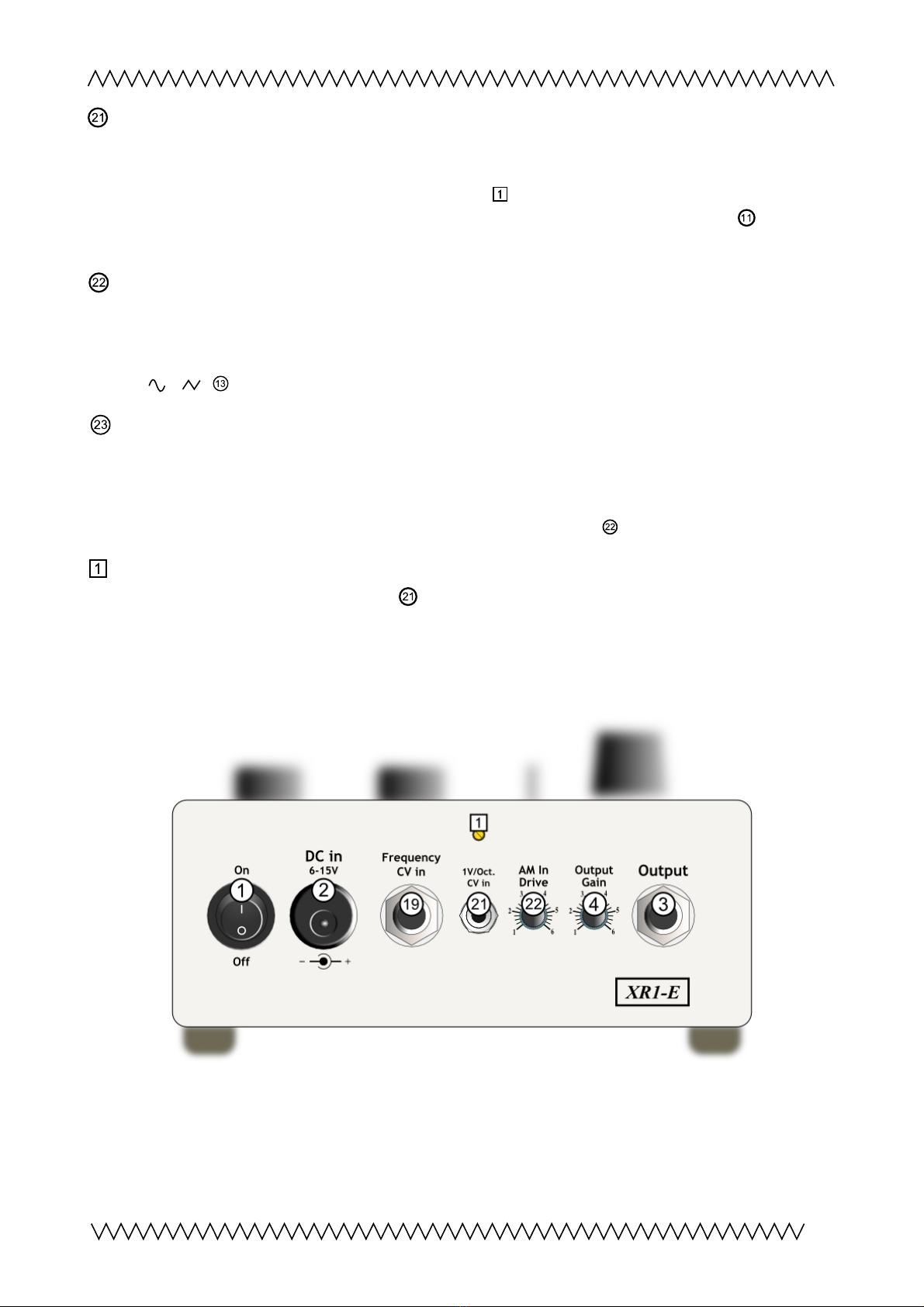
1V/octave minijack input (new from Rev.4)
If intended, the oscillator's frequency can be controlled by an external control voltage, for
example from a modular synthesizer, with 1V/octave calibration There is a trimmer above this
socket (behind the hole in the casing) for adjustment
23456789
21
10 11 13 14 15 16 17 18 19
20 22
12
Objekt in Pfade:
4
4
14
Falsche Zahlen
4
The oscillator's 1V/oct behaviour is not
very linear over its whole range, best results will be achieved with the frequency knob set to ≈
2-5 on its scale
AM In Drive knob (new from Rev.4)
Together with the preamp knob, the preamplification for the oscillator's amplitude modulation
input can be adjusted This 2nd controller is allowing to overdrive the oscillator's amplitude
modulation input and enhances the sound possibilities, especially in combination with wavefrom
switch ' / '
Bicolor LED 'AM'
The green lightning signalizes normal and no overdriven operation Red lightning indicates that
the preamp is becoming overdriven, this may result in distortion
Yellow or orange colors signalize when the oscillator's amplitude modulation input comes into
saturation and starts to overdrive – regarding to knob 'AM In Drive'
23456789
21
10 11 13 14 15 16 17 18 19
20 22
12
Objekt in Pfade:
4
4
14
Falsche Zahlen
4
1V/Octave calibration trimmer
If required, the 1V/octave minijack input (on the backside) can be calibrated by the trimmer
behind the hole (use a tiny screwdriver) for best 1V/oct matching
Back Side View
7
23456789
21
10 11 13 14 15 16 17 18 19
20 22
12
Objekt in Pfade:
4
4
14
Falsche Zahlen
4
2 3 456789
21
10 11 13 14 15 16 17 18 19
20 22
12
Objekt in Pfade:
4
4
14
Falsche Zahlen
48
9
10
11
12
23
23456789
21
10 11 13 14 15 16 17 18 19
20 22
12
Objekt in Pfade:
4
4
14
Falsche Zahlen
4
23456789
21
10 11 13 14 15 16 17 18 19
20 22
12
Objekt in Pfade:
4
4
14
Falsche Zahlen
4

About Ring Modulation
'Ring modulation' and 'amplitude modulation' are different expressions for almost the same
operation, the
multiplication
of two signals The audio result is both identical
The difference between the 2 expressions is: 'Amplitude modulation' describes the multiplication
of
any
kind of analog signals, therefore such as control (DC) voltages; while 'ring modulation' is a
term for the special case of multiplication of two bipolar audio signals (AC) with each other
Each value of a carrier signal,
C
, is multiplied by a modulator signal,
M
, to create a new
ring-
modulated
signal,
R
:
R(t) = C(t) x M(t)
(Wikipedia)
Due to the
XR1-E ,
the internal oscillator tone
or
is multiplied with the audio input
Examples
Input (=modulator) signal frequency >> oscillator (carrier) frequency ( ):
Input signal: metallophone
The volume of he me allophone sound varies wi h he oscilla or ampli ude ( remolo).
Input (=modulator) si nal frequency << oscillator (carrier) frequency ( )
Input signal: "Base drum" from rhythm machine
The generated effect signal
The volume of he oscilla or sound varies wi h he ampli ude of he inpu signal
Input (=modulator) si nal frequency ≤ or ≥ oscillator (carrier) frequency ( )
Input signal: "Mid tom" from rhythm machine
Complexe sound structures are generated, depending on the oscillator frequency
8

Contact
Christian Günther
Forster Str 50
10999 Berlin
cg@mandalamat de
Phone: ++49 30 61286299
Mobile ++49 178 7699267
www cg-products de
XR1-E
website with video and soundfiles: http://www cg-products de/xr1-e/
Youtube: https://www youtube com/watch?v=2zDMeQAN_4I
Soundcloud: https://soundcloud com/cg-products/sets/xr1-e
This documentation is for XR1-E Rev 4
www cg-products de/XR1-E_documentation pdf
For further versions (without switch 'S+H' ) please see here:
www cg-products de/XR1-E_documentation_Rev 3 pdf
© Chris ian Gün her 2020
9
Other manuals for XR1-E
2
Table of contents
Other CG Products Modulator manuals


Popular Modulator manuals by other brands


DRAKE
DRAKE VM2860 instruction manual

Comtech EF Data
Comtech EF Data Radyne DM240XR Installation and operation manual

acid rain technology
acid rain technology Maestro Quick reference guide

Sennheiser
Sennheiser Dishwasher Product sheet

Audiovox
Audiovox SPS CDC-MC1 owner's manual

Radio Shack
Radio Shack Video RF Modulator owner's manual