CH Hanson PALMGREN 9661616 Instructions for use
Operating Instructions & Parts Manual EN
50 Ton Electric
Hydraulic Press
Model 9661616
9643571.01

PLEASE READ AND SAVE
THESE INSTRUCTIONS.
READ CAREFULLY
BEFORE ATTEMPTING
TO ASSEMBLE, INSTALL,
OPERATE OR MAINTAIN THE
PRODUCT DESCRIBED.
PROTECT YOURSELF AND
OTHERS BY OBSERVING ALL
SAFETY INFORMATION. FAILURE
TO COMPLY WITH INSTRUCTIONS
COULD RESULT IN PERSONAL
INJURY AND/OR PROPERTY
DAMAGE! RETAIN INSTRUCTIONS
FOR FUTURE REFERENCE.
PLEASE REFER TO BACK COVER
FOR INFORMATION REGARDING
PALMGREN’S WARRANTY
AND OTHER IMPORTANT
INFORMATION.
Model #: ___________________
Serial #: ___________________
Purch. Date: _______________
© 2019 Palmgren / a C.H. Hanson Brand
All Rights Reserved
3
GETTING STARTED SAFETY / SPECIFICATIONS ASSEMBLY / INSTALLATION OPERATION TROUBLESHOOTING MAINTENANCE / REPAIR
GETTING STARTED
Save this manual
You will need this manual for the safety warnings and precau-
tions, assembly instructions, operating and maintenance
procedures, parts lists and diagrams. Keep your invoice with this
manual. Write the invoice number on the inside of the front cover.
Keep this manual and invoice in a safe and dry place for future
reference.
Structural requirements
Make sure all supporting structures and load attaching
devices are strong enough to hold your intended loads.
If in doubt, consult a qualified structural engineer.
Electrical Requirements
• Requires 230V at 60 Hz, with a standard deviation of 10%
• A plug, rated for 230V, 13A, and 2.2 KW, is required to be
wired. Ensure the ground wire(yellow+green) is correctly
wired to the ground of the plug. It does not matter which side
of the plug the two black wires are wired to.
Tools needed
Standard professional mechanic’s hand tool set (i.e. hammer,
screwdrivers, wrenches, socket wrenches, pliers, etc.).
UNPACKING
When unpacking, check to make sure all parts listed below are
included. If any parts are missing or broken, please contact your
local retailer.
IMPORTANT: Many unpainted steel surfaces have been
coated with a protectant. To ensure proper fit and operation,
remove the coating. Coating can be easily removed with mild
solvents, such as mineral spirits, and a soft cloth. Avoid getting
solution on paint or any of the rubber/plastic parts. Solvents may
deteriorate these finishes. Use soap and water on paint, plastic
or rubber components. After cleaning, cover all exposed surfaces
with a light coating of oil.
Never use highly volatile solvents. Avoid
getting cleaning solution on paint as it
may tend to deteriorate these finishes. Use soap and water
on painted components.
Package Contents:
Pipe holders 2
Frame with cylinder 1
Hydraulic pump assembly 1
Replacement rubber o-rings
and hardware
1
Ram cap 1
Manual 1
Unpack
Remove all the over packing materials, but leave unit
attached to its pallet. Do not discard packing materials
until after the machine has been inspected for damage and
completeness. Locate loose parts and set aside.
Inspect
After unpacking the unit, carefully inspect for any
damage that may have occurred during transit. Check
for loose, missing or damaged parts. Shipping damage
claims must be filed with the carrier.
All tools should be visually inspected before use, in addition to
regular periodic maintenance inspections.

MAINTENANCE / REPAIR TROUBLESHOOTING OPERATION ASSEMBLY / INSTALLATION SAFETY / SPECIFICATIONS GETTING STARTED
4
SAFETY RULES
Completely read and understand this
owner’s manual before assembly or tool
operation. Read and understand the warnings shown on the
machine and in this manual. Failure to comply with all of
these warnings may cause serious injury or death.
PROPOSITION 65 WARNING: Some dust created by
using power tools contain chemicals known to the state
of California to cause cancer, birth defects or other
reproductive harm.
Some Examples of these chemicals are:
• Lead from lead-based paints
• Crystalline silica from bricks and cement and other masonry
products.
• Arsenic and chromium from chemically-treated lumber.
Your risk from these exposures varies, depending on how often
you do this type of work. To reduce your exposure to these
chemicals: work in a well ventilated area and work with approved
safety equipment. Always wear an OSHA/NIOSH approved,
properly fitting face mask or respirator when using such tools.
Always follow proper operating
procedures as defined in this manual
even if you are familiar with the use of this or similar tools.
Remember that being careless for even a fraction of a
second can result in severe personal injury.
PREPARING FOR YOUR JOB
• Wear proper apparel. Do not wear loose clothing, neckties,
rings, bracelets or other jewelry which may get caught up in
moving parts of machine. Do NOT wear gloves.
• Wear protective hair covering to contain long hair.
• Wear safety shoes with non-slip soles.
• Wear safety glasses complying with United States ANSI
Z87.1. Everyday glasses have only impact resistant lenses.
They are not safety glasses. Use guards and eye shields.
• Wear face mask or dust mask if operation is dusty.
• Wear ANSI approved ear protection for extended operation.
• Some coolants used for machining contain chemicals that
may be hazardous to your health if not used properly. Read
and understand all information on the coolant container and
protect yourself accordingly.
• Be alert and think clearly. Never operate power tools when
tired, intoxicated or when taking medications that cause
drowsiness.
• Focus your attention completely on your work. Looking
around, careless actions and other distractions can result in
serious injury.
Preparing the work area for your job
• Do not use this machine in dangerous environments. Do not
use it in damp or wet locations. Do not expose it to rain.
• Keep the work area clean. Cluttered work areas and work
benches invite accidents. Keep the area around the machine
clean of scrap metal, oil and grease.
• Keep visitors at a safe distance from work area.
• Keep children out of workplace. Make workshop childproof.
Use padlocks, master switches or remove switch keys to
prevent any unintentional use of power tools.
• Provide adequate space around the hydraulic press and light
the area properly with non-glare, overhead lighting.
• Make certain the hydraulic press is securely anchored before
use.
Maintaining your tool
• Failure to follow the guidelines in this manual can result in
serious injury.
• Disconnect the tool completely from its power supply before
performing any service, maintenance, repair or adjustments.
• Follow OSHA lock-out, tag-out procedures to prevent
accidental machine starts.
• Consult this manual for the proper use, specific maintenance,
and adjustment procedures.
• Keep tool lubricated and clean for safest operation.
• Read and understand warnings posted on the machine and
in this manual. Replace the warning labels if they become
obscured or removed. Failure to comply with all of these
warnings can result in serious injury.
• Before turning on the machine, check for damaged parts.
Check for alignment of moving parts, binding, breakage,
mounting issues and any other conditions that may affect
the tools operation. Replace any guard or damaged part that
does not function properly before using the tool.
• Before cleaning, turn off the machine and disconnect it from
its power source. Use compressed air or a suitable brush to
clear chips or debris — do not use your hands.
Know how to use your tool
The operation of any tool can result in
foreign objects being thrown into the
eyes, which can result in severe eye damage. Always wear
safety goggles complying with United States ANSI Z87.1.
before commencing power tool operation.
Think safety! Safety is a combination of operator
common sense and alertness at all times when tool
is being used.
• The Model 9661616 Hydraulic Press is designed and
intended for use by properly trained operators. You must
be familiar with the proper and safe operation of a hydraulic
press. Obtain proper training and knowledge before operating
this machine.

5
GETTING STARTED SAFETY / SPECIFICATIONS ASSEMBLY / INSTALLATION OPERATION TROUBLESHOOTING MAINTENANCE / REPAIR
• Do not use the Model 9661616 Hydraulic Press for any use
other than its intended application. Improper use of this
tool revokes and voids any real or implied warranty. The
manufacturer is not responsible for any injury that may result
from improper use of the machine.
• Do not force an attachment to do a job it was not intended or
designed for.
• Never stand on the machine or work in an awkward position.
Maintain your balance. Never lean against the machine, over
reach or use excessive force when working. You could tip or
fall into the machine causing serious injury.
• Know your tool. Learn the tool’s operation, application and
specific limitations. Never force the machine to do a task it
was designed for.
• Use recommended accessories. Understand and obey all
safety instructions supplied with accessories. The use of
improper accessories may cause risk of injury to persons.
• Always use guards and eyeshields.
SPECIFICATIONS
Model 9661616 50 Ton Electric Hydraulic Press
Capacity (tons) 50
Stroke travel (inch) 8.7
Ram diameter (inch) 1.5 (or 2.25 with ram cap)
Table Size (inch) 16x20 with 4” dia. hole
Max distance ram to table (inch) 27
Head movement No
Dimension (inch) 35x14x62
Weight (lbs) 705
RPM 3450
Volts 230
Amps 13
KW/HP 2.2/3
Phase 1
Operating temperature °F (°C) 50-122 (10-50)
ASSEMBLY/INSTALLATION
Power source
• The motor on this machine is designed for operation on
the voltage and frequency specified. Normal loads will be
handled safely on voltages not more than 10% above or
below specified voltage.
• Running the unit on voltages which are not within the range
may cause overheating and motor burn-out. Heavy loads
require that the voltage at the motor terminals be no less than
the voltage specified.
Electrical connections
Make sure unit is turned off and
disconnected from power before
performing service or maintenance actions on the machine.
This machine must be grounded. To avoid
electrocution or fire, any repairs to
electrical system should be done only by a qualified
electrician, using genuine replacement parts.
Electrical safety
• This machine must be grounded in accordance with the
National Electrical Code and local codes and ordinances. Any
electrical work must be handled by a professional, qualified
electrician. To help prevent and protect the user from shock,
this machine must be properly grounded.
• Confirm that power supply matches power requirements of
the machine before any electrical connection is made to the
machine. Before connecting the machine to a power source,
ensure that the switch is in the off position.
Lifting and setting up your machine
Make certain that slings, cables, chains,
forklifts or other load suspending gear or
machines used to move this unit are properly rated to
handle the weight. The machine is extremely heavy.
The machine must be properly secured
and anchored before use. Make sure that
it is supported equally on all four corners. Failure to comply
may result in the machine twisting and causing binds in the
working table.
1. The machine arrives assembled and ready to us except
that it requires proper electrical wiring to be installed. Have
an authorized electrician prepare an electrical box near the
machine’s installation location.
2. Remove any crating or overpacking materials which may be
covering the machine. Leave the machine attached to the
pallet.

TROUBLESHOOTING OPERATION ASSEMBLY / INSTALLATION SAFETY / SPECIFICATIONS GETTING STARTED
6
MAINTENANCE / REPAIR
NOTE: The Model 9661616 Hydraulic Press weighs 507 lbs. Be
certain any machine or devices used to lift the press are
capable of handling this weight. If manually lifting, ensure
that enough people are performing the lift.
3. Ensure sufficient space is available for the press. See
Machine Dimensions.
4. Remove all accessory items from the pallet or shipping
carton. Compare these items with the listed on page 3.
5. Remove all the nuts and/or bolts securing the machine to the
pallet.
6. Center an overhead crane or other suitable overhead lifting
device and sling arrangement over the frame.
7. Carefully lift the machine off the pallet. Lift the machine no
higher than necessary to clear the surface on which it is to
be installed and pull the pallet out of the way. DO NOT get
your hands or feet underneath the machine when removing
the pallet.
8. Place the machine into its final location where it will be
anchored to the table top. Anchor bolts of sufficient size and
length must be fastened to the table top according to the
footprint of the press.
9. While it is not recommended, the machine may be mounted
to a wooden floor. The floor must be sturdy and properly
braced to ensure a solid foundation for safety and machine
accuracy.
10. When the machine is over its anchor location, level the
machine using shims under the corners needing them. A
highly accurate spirit or digital level should used for leveling.
Leveling should be done on the table top since it is the
reference standard for both side-to-side and front-to-back
leveling. It is very important that the machine be properly
leveled for accurate performance.
Note: The diagrams to the right show the reasonable
approximate dimensions of the machine and its parts. When
determining a final location for your machine ensure there is
enough clearance for both the operator and for technicians
who will service the machine. Also, consider any larger
workpieces that would extend beyond the machine’s table
and require extra space.
11. Have an authorized electrician connect the machine to the
power source installed in step 1. If required, install a plug
the machine’s electrical cable if it is to be plugged in and not
hard-wired.
Note: The direction of the motor will be shown as a large red
arrow on the motor.
Machine dimensions
62”
35”
14”
Lubrication
Do not operate this machine before
lubrication and ensuring proper oil level.
Failure to comply may damage the machine.
Fill the pump with 32# or 46# hydraulic oil as shown by the fill
indications.
7
GETTING STARTED SAFETY / SPECIFICATIONS ASSEMBLY / INSTALLATION OPERATION TROUBLESHOOTING MAINTENANCE / REPAIR
OPERATION
Always wear safety glasses complying
with U.S. ANSI Z87.1 before beginning any
power tool operation.
Do not operate this machine before
properly lubricating the machine. Failure
to lubricate the machine before using can cause damage to
the machine.
If the temperature exceeds the maximum
operating temperature (see ) wait until
cool.
Do not use the press with no load and when
the piston rod is on the up dead position.
NOTE: The machine is adjusted to produce proper pressure at
the factory.
Using the press
1. Ensure that the piece to be pressed is centered on the table
with respect to the piston.
Pieces to be pressed must have a
compact, solid structure and must not be
subject to crumbling or other structural damage potential.
And do not activate the press with no load.
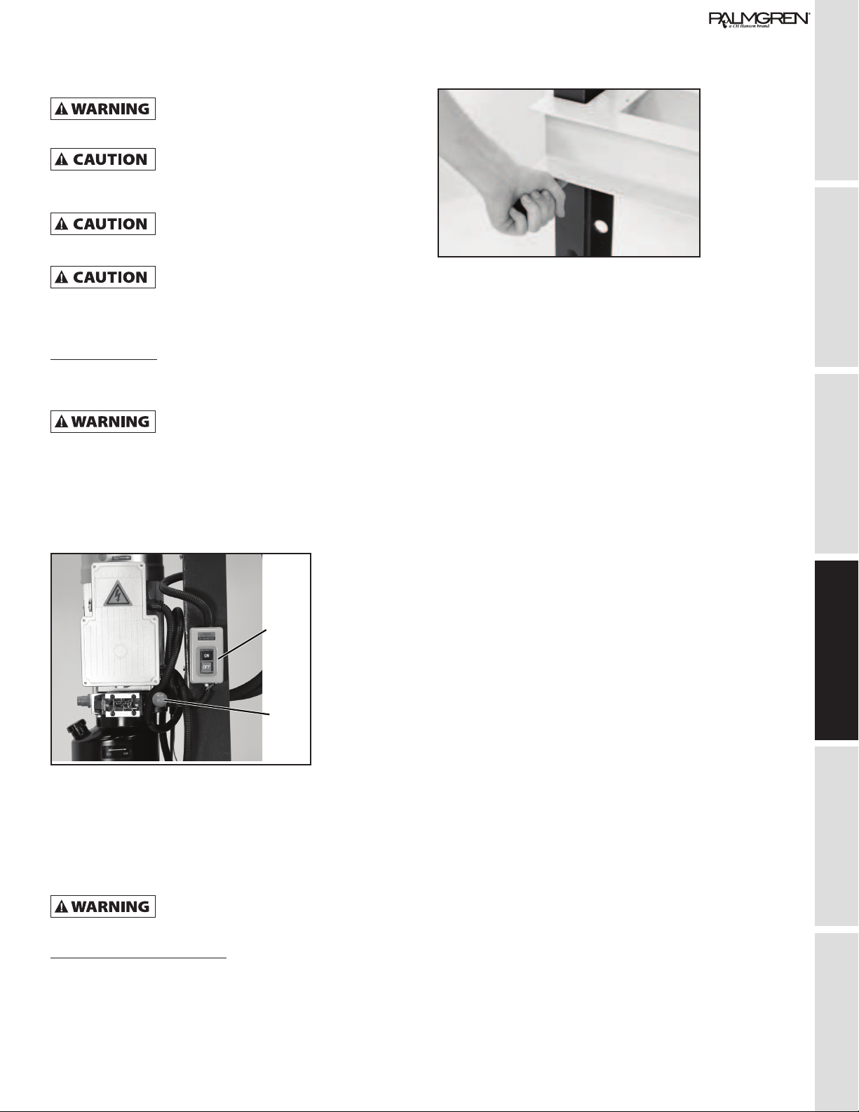
2. Before starting the pump, ensure the direction valve handle
is set to the center position.
3. Turn the motor on by pressing the “ON” button as shown
below. Pressing the “OFF” button will shut the motor off.
On/O
Switch
Direction
Control
Lever
4. The piston is controlled by a direction control lever (with a
red ball handle) shown above. The lever has 3 states:
• Left : Up
• Middle: Stop
• Right: Down
When using the press beware of any part
that could be ejected out the front, by the
force applied.
Adjusting the table height
1. Unload the table of all extra items.
2. Lift the table support beam on one side. We recommend
asking for assistance in holding the beam, although it is
possible to do so only by oneself.
3. Extract the support pin as shown below.
4. Insert the pin into the next adjacent hole, either above or
below the original hole. Make sure to insert the pin all the
way through both the front and back of the hydraulic press
frame.
5. Then ease the support beam back onto the pin. When done
this way, only one person is required.
6. Repeat all previous steps for the opposite side.
7. Repeat until the desired height achieved.

MAINTENANCE / REPAIR TROUBLESHOOTING OPERATION ASSEMBLY / INSTALLATION SAFETY / SPECIFICATIONS GETTING STARTED
8
TROUBLESHOOTING GUIDE
Symptom Possible Cause(s) Corrective Action
Ram does not move • Low oil condition
• Not enough pressure
• Fill oil
• Check motor
Ram does not press Cylinder valve not closed Close cylinder valve
Motor does not run Power disconnected Check on/off switch and circuit breaker
9
GETTING STARTED SAFETY / SPECIFICATIONS ASSEMBLY / INSTALLATION OPERATION TROUBLESHOOTING MAINTENANCE / REPAIR
MAINTENANCE/REPAIR
Before any maintenance is performed, ensure all pressure has
been released.
Daily
• General visual inspection-check for any visible damage or
missing parts
• Check that all labels are clearly visible- must be legible as
well
• Check for any leaks in the hydraulic units
• Check the up/down lever is in the stop (middle) position when
not in use
Weekly
• Check oil level
• General cleaning
Monthly
• Check wear on the hydraulic piston and station
• Check tightness of the bolts
Half Year
• Refill with #32 or #46 Hydraulic oil every 6 months. After
refilling, have the piston move up and down to remove the air
from the inside the cylinder.
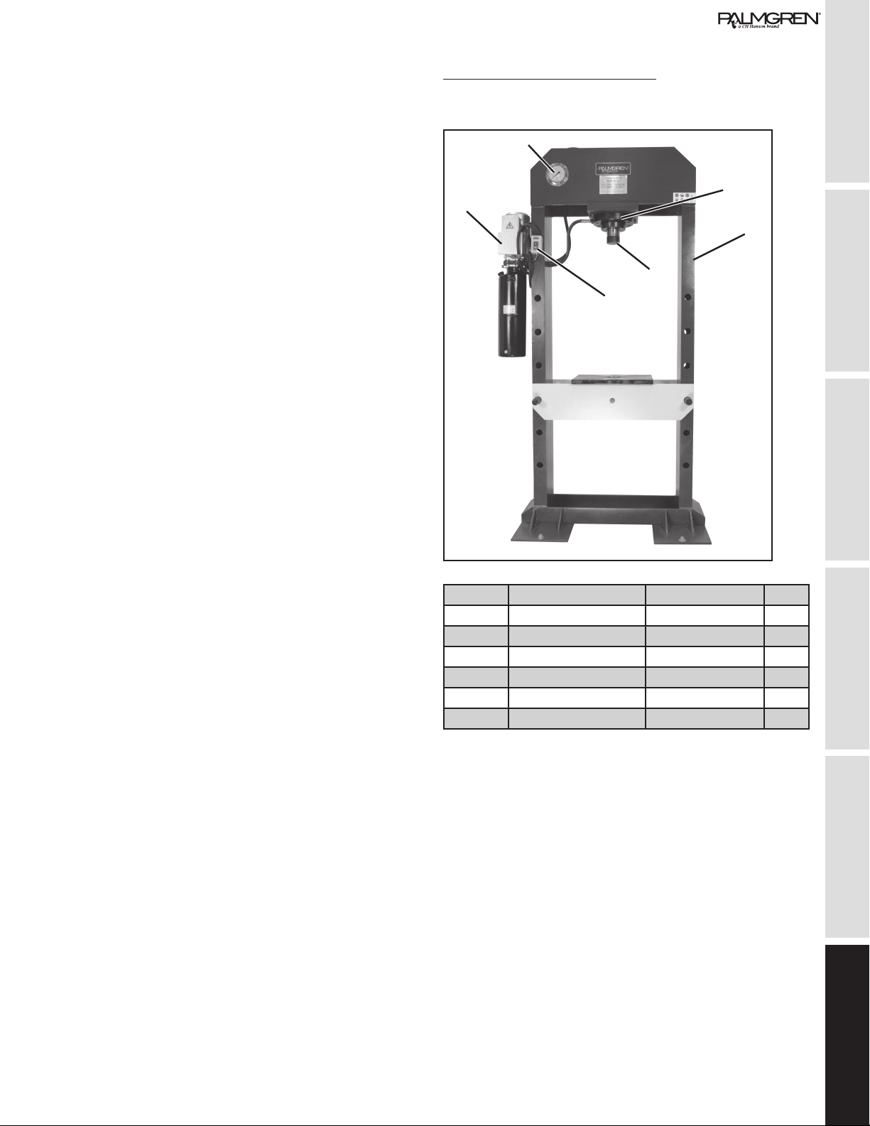
The machine’s functional parts
To properly operate the Model 9661616 Hydraulic Press, you
must familiarize yourself with all of the machine’s controls.
1
2
4
5
3
6
Item No. Description Part No. Qty
1 Cylinder 9643620.01 1
2 Framework NA 1
3 Motor 9643574.01 1
4 Hydraulic Gauge 9643622.01 1
5 On/Off Switch 9643576.01 1
6 Ram Cap 9643621.01 1

MAINTENANCE / REPAIR TROUBLESHOOTING OPERATION ASSEMBLY / INSTALLATION SAFETY / SPECIFICATIONS GETTING STARTED
10
MAINTENANCE/REPAIR -
CROSS SECTION OF PISTON
Item No. Description Qty Item No. Description Qty
1 Oil Vat 1 7 Pressurize Ring 1
2 Stopcock 1 8 Pressurize Ring 1
3 Piston Ring 1 9 Pressurize Ring 1
4 Pressurize Ring 1 10 Vat Cover 1
5 Piston Shaft 1 11 Pressurize Ring 1
6 Pressurize Ring 1 12 Flange 1
ELECTRICAL SCHEMATIC

GETTING STARTED SAFETY / SPECIFICATIONS ASSEMBLY / INSTALLATION OPERATION TROUBLESHOOTING MAINTENANCE / REPAIR
11
HYDRAULIC SCHEMATIC

PALMGREN WARRANTY
C.H. Hanson / Palmgren warrants their products to be free of defects in material or
workmanship. This warranty does not cover defects due directly or indirectly to misuse,
abuse, normal wear and tear, failure to properly maintain the product, heated, ground or
otherwise altered, or used for a purpose other than that for which is was intended.
The warranty does not cover expendable and/or wear part (i.e. v-belts, screws, abrasives,
jaws), damage to tools arising from alteration, abuse or use other than their intended
purpose, packing and freight. The duration of this warranty is expressly limited to the terms
noted below beginning from the date of delivery to the original user.
The Palmgren branded items carry the following warranties on parts:
All vises, clamps, positioning tables, tombstones, jack screws and vise
accessories - LIFETIME.
All bench grinders, drill presses, tapping machines, band saws, lathes, milling
machines, arbor presses, abrasive finishing machines and work stands - 3
YEARS.
The obligation of C.H. Hanson / Palmgren is limited solely to the repair or replacement, at
our option, at its factory or authorized repair agent of any part that should prove inoperable.
Purchaser must lubricate and maintain the product under normal operating conditions at
all times. Prior to operation become familiar with product and the included materials, i.e.
warnings, cautions and manuals.
Failure to follow these instructions will void the warranty.
This warranty is the purchaser’s exclusive remedy against C.H. Hanson for any inoperable
parts in its product. Under no circumstances is C.H. Hanson liable for any direct, indirect,
incidental , special or consequential damages including loss of profits in any way elated to
the use or inability to use our products. This warranty gives you specific legal rights which
may vary from state to state.
Palmgren - a C.H. Hanson Company
2000 N. Aurora Rd., Naperville, IL
60563
U.S.A.
or call 1-800-827-3398
Table of contents
Other CH Hanson Power Tools manuals


