CH Hanson Norse 9680202 Instructions for use

8˝ Drill Press
Operating Instructions & Parts Manual
9640915.01 0318
Model 9680202
9680202_oipm_En011_9640915.01 03/21/18 Page 1

2
GE ING S AR ED
SAFE Y / SPECIFICA IONS
ASSEMBLY / INS ALLA ION
OPERA ION
ROUBLESHOO ING
MAIN ENANCE / REPAIR
NOR E Operating Manual & Parts List 9680202
Please read and save hese ins ruc ions. Read carefully before a emp ing o assemble, ins all,
opera e or main ain he produc described.
Pro ec yourself and o hers by observing all safe y informa ion. Failure o comply wi h ins ruc ions
could resul in personal injury and/or proper y damage! re ain ins ruc ions for fu ure reference.
Model #: ________________________
Serial #: _________________________
Purchase Da e: ___________________
9680202_oipm_En011_9640915.01 03/21/18 Page 2
GE ING S AR ED
Save his Manual
You will need the manual for the safety warnings and pre cautions,
assembly instructions, operating and maintenance procedures,
parts list and diagram. Keep your invoice with this manual. Write
the invoice number on the inside of the front cover. Keep this
Manual and invoice in a safe and dry place for future reference.
Structural Requirements
Ensure all supporting structures and load attaching devices are
strong enough to hold the intended loads. If in doubt, consult a
qualified structural engineer.
Electrical Requirements
The power supply to the 8” Bench Model Drill Press needs to be
120 volts, single phase, 60 Hz. The standard allowable voltage
variation is plus or minus 10%.
ools Needed:
Standard mechanic’s hand tool set (i.e. hammer, screwdrivers,
adjustable wrenches, etc.).
UNPACKING
When unpacking, check to make sure all parts listed below are
included. If any parts are missing or broken, please contact your
local retailer.
IMPOR AN : Many unpainted steel surfaces, such as the column
and table top, have been coated with a protectant. To ensure
proper fit and operation, remove coating. Coating can be easily
removed with mild solvents, such as mineral spirits, and a soft
cloth. Avoid getting solution on paint or any of the rubber/ plastic
parts. Solvents may deteriorate these finishes. Use soap and water
on paint, plastic or rubber components. After cleaning, cover all
exposed surfaces with a light coating of oil. Paste wax is
recommended for table top.
Never use highly vola ile solven s.
Nonflammable solven s are recommended
o avoid possible fire hazard.
Contents:
• Head assembly/motor (1)
• Base (1)
• Column (1)
• Table assembly (1)
• Handles (3)
• Chuck/chuck key (1)
• Table lock handle (1)
• 3mm hex-wrench (1)
• 4mm hex-wrench (1)
• Operating Instructions & Parts Manual (1)
Unpack
Open carton and carefully remove the top Styrofoam section,
containing the base, table assembly, chuck box, and hardware bag.
Then remove the head assembly and column from the lower
Styrofoam section. Do not discard packing materials until after the
machine has been inspected for damage and completeness.
Locate loose parts and set aside.
Inspect
After unpacking the unit, carefully inspect for any damage that may
have occurred during transit. Check for loose, missing, or damaged
parts. Shipping damage claims must be filed with the carrier. All
tools should be visually inspected before use, in addition to regular
periodic maintenance inspections. Be sure that the voltage labeled
on the unit matches your power supply.
SAFE Y RULES
For you own safe y, read all of he
ins ruc ions and precau ions before
opera ing he ool.
PROPOSI ION 65 WARNING: Some dust created by
using power tools contain chemicals known to the state
of California to cause cancer, birth defects or other
reproductive harm. Some Examples of these chemicals are:
• Lead from lead-based paints
• Crystalline silica from bricks and cement and other masonry
products
• Arsenic and chromium from chemically-treated lumber
Your risk from these exposures varies, depending on how often you
do this type of work. To reduce your exposure to these chemicals:
work in a well ventilated area and work with approved safety
equipment. Always wear OSHA/NIOSH approved, properly fitting
face mask or respirator when using such tools.
When using he ool, basic safe y
precau ions should always be followed o
reduce he risk of personal injury and damage o equipmen .
Read All Instructions Before Using his ool!
• Dress properly. Do not wear loose clothing or jewelry as they
can be caught in moving parts. Protective, electrically non -
conductive clothes and non-skid footwear are recommended
when working. Wear restrictive hair covering to contain long hair
• Use eye and ear protection. Always wear ANSI approved
impact safety goggles.
• Stay alert. Watch what you are doing, use common sense. Do
not operate any tool when you are tired.
• Guard against electrical shock. Prevent body contact with
grounded surface such as pipes, radiators, ranges and
refrigerator enclosure.
• Do not operate tool if under the influence of alcohol or drugs.
Read warning labels on prescriptions to determine if your
judgement or reflexes will be impaired. If there is any doubt, do
not operate the tool.
3
NOR E Operating Manual & Parts List 9680202
GE ING S AR ED SAFE Y / SPECIFICA IONS ASSEMBLY / INS ALLA ION OPERA ION ROUBLESHOO ING MAIN ENANCE / REPAIR
9680202_oipm_En011_9640915.01 03/21/18 Page 3

SAFE Y RULES CON INUED
Prepare Work Area for Job
• Keep work area clean. Cluttered areas invite injuries.
• Observe work area conditions. Do not use machines or power
tools in damp or wet locations. Do not expose to rain.
• Keep work areas well lighted. Do not use electrically powered
tools in the presence of flammable gases or liquids.
• Keep children away. Children must never be allowed in the
work area. Do not let them handle machines, tools or extension
cords.
• Use proper size and type extension cord.
• If an extension cord is required, it must be of proper size and
type to supply the correct current to the tool without heating up.
Otherwise, the extension cord could melt and catch fire, or
cause electrical damage to the tool. If you are using the tool
outdoors, use an extension cord rated for outdoor use
(signified by “WA” on the jacket).
ool Should Be Maintained
• Store idle equipment. When not in use, tools must be stored in
a dry location to inhibit rust. Always lock up tools and keep out
of reach of children.
• Maintain tools with care. Keep tools sharp and clean for better
and safer performance. Follow instructions for lubricating and
changing accessories. Inspect tool cords periodically and if
damaged, have them repaired by an authorized technician.
The handles must be kept clean, dry and free from oil and
grease at all times.
• Disconnect power. Unplug too when not in use.
• Replacement parts and accessories. When servicing, use only
identical replacement parts. Use of any other parts will void the
warranty. Only use accessories intended for use with this tool.
Approved accessories are available from your local retailer.
• Maintenance. For your safety, service and maintenance should
be performed by a qualified technician.
Know How to Use ool
• Do not force tool. It will do the job better and more safely at the
rate for which it was intended. Do not use inappropriate
attachments in an attempt to exceed the tool capacity.
• Use the right tool for the job. Do not attempt to force a small
tool or attachment to do the work of a large industrial tool.
There are certain applications for which this tool was designed.
Do not modify this tool and do not use this tool for a purpose
for which it was not intended.
• Do not overreach. Keep proper footing and balance at all times.
Do not reach over or across machines while in operation.
• Remove adjusting keys and wrenches. Check that keys and
adjusting wrenches are removed from the tool or machine work
surface before plugging it in.
• Avoid unintentional starting. Be sure the switch is in the OFF
position when not in use and before plugging in.
• Check for damaged parts. Before using any tool, any part that
appears damaged should be carefully checked to determine
that it will operate properly and perform its intended function.
Check for alignment and binding of moving parts; any broken
parts or mounting pieces should be properly repaired or
replaced by a qualified technician. Do not use the tool if any
switch does not turn ON and OFF properly.
The warnings, cau ions and ins ruc ions
discussed in his ins ruc ion manual
canno cover all possible condi ions and si ua ions ha may
occur. I mus be unders ood by he opera or ha common
sense and cau ion are fac ors which canno be buil in o
his produc , bu mus be supplied by he opera or.
SPECIFICA IONS*
Chuck size 1/2˝
Spindle taper T33
Spindle travel 2˝
Spindle axis to column surface distance 4˝
Spindle to base surface distance 111⁄2˝
Spindle to table surface max distance 81⁄4˝
Spindle speeds 5
Spindle RPM 750 – 3200
Table dimensions 61⁄2˝ x 61⁄2˝
Table rotation around column 360°
Base size (L x W) 103⁄4˝ x 7˝
Overall dimension (L x W x H) 17˝ x 8˝ x 23˝
Net weight 35 lbs.
Motor 120V, 2.3A, 300W, 1/3 HP, 60 Hz
Motor RPM 1725
Column diameter 1-13/16” or 46mm
*NOTE: Spindle measurements are from the bare spindle without
the chuck.
4
GE ING S AR ED
SAFE Y / SPECIFICA IONS
ASSEMBLY / INS ALLA ION
OPERA ION
ROUBLESHOO ING
MAIN ENANCE / REPAIR
NOR E Operating Manual & Parts List 9680202
9680202_oipm_En011_9640915.01 03/21/18 Page 4
ASSEMBLY
ools Needed for Entire Assembly
• Adjustable wrench
• Hammer with block of wood or rubber hammer
• Screwdriver
Base to Column
1. Place the base on a stable surface (either on a sturdy table or
the floor)
2. Set the column on the base, making sure to line up the three
holes in both the base and column.
3. Insert a bolt, first with a lock washer then a flat washer, into
each hole.
4. Tighten with a wrench.
able to Column
1. Slide the table’s sleeve onto the column and set at desired
height.
2. Make sure to line up and center the table to the base, below.
3. Use the handle to tighten and lock in position.
Drill Press Head to Column
1. Carefully place the head on the column, and ensure the head
is seated properly on the column.
2. Align the drill spindle with the table and base.
3. Using the provided Allen wrenches, tighten the set screws on
the side of the drill head, until the drill head can no longer
swivel on the column.
Install the Drill Chuck
1. Using a clean cloth, inspect and clean the spindle and tapered
hole of the chuck. Remove all grease, coatings and particles.
2. Ensure the chuck jaws are fully retracted.
3. Fit the chuck onto the spindle by placing a piece of wood under
the chuck and tapping the wood with a hammer, or use a
rubber hammer instead of the wood and normal hammer.
Do no direc ly hi he chuck wi h a
normal hammer.
Mount the Drill Press
If needed, the drill press can be mounted to a stand or work bench
with heavy duty fasteners, using the slots on the base.
INS ALLA ION
All elec rical connec ions mus be
performed by a qualified elec rician.
Power Source
The motor is designed for operation on the voltage and frequency
specified. Normal loads will be handled on voltages not more than
10% above or below the specified voltage.
Running the unit on voltages which are not within the range may
cause overheating and motor burn-out. Heavy loads require that
the voltage at motor terminals be no less than the voltage specified.
Grounding Instructions
Improper connec ion of equipmen
grounding conduc or can resul in he risk
of elec rical shock. Equipmen should be grounded while
use o pro ec opera or from elec rical shock.
Check with qualified electrician if grounding instructions are not
understood or if in doubt as to whether the tool is properly
grounded.
Extension Cords
• Your tool has a three-prong plug; therefore, you must use a
three-prong extension cord. Only use rounded jacket extension
cords listed by the UL.
• Improper use of extension cords may cause inefficient
operation of your tool which can result in overheating. Be sure
your extensions cord is rated to allow sufficient current flow to
the motor. If you are using the tool outdoors, use an extension
cord rated for outdoor use (signified by “WA” on the jacket).
• Avoid body contact with the grounded surfaces such as pipes
radiators, ranges and refrigerators. There is an increased risk
of electric shock if your body is grounded. If operating the
power tool in damp locations is unavoidable, a Ground Fault
Circuit Interrupter must be used to supply the power to your
tool. Electrician’s rubber gloves and footwear will further
enhance your personal safety.
• Don’t expose power tools to rain or wet conditions. Water
entering a power tool will increase the risk of electric shock.
• Do not abuse the cord. Never use the cord to carry the tool or
pull the plug from an outlet. Keep cord away from heat, oil,
sharp edges or moving parts. Replace damaged cords
immediately. Damaged cords increase risk of electric shock.
• The use of an extension cord will cause some drop in voltage
and loss of power.
• Wires of the extension cord must be of sufficient size to carry
the current and maintain adequate voltage.
• Use only 3-wire extension cords, having 3-prong grounding
type plugs and 3-pole receptacles which accept the tool plug.
• If the extension cord is worn, cut or damaged in any way,
replace it immediately.
• For wire size, lengths up to 25 ft. have an A.W.G of 16. 25 ft. to
100 ft. have an A.W.G. of 14 NOTE: Using extension cords
over 100 ft. are not recommended.
5
NOR E Operating Manual & Parts List 9680202
GE ING S AR ED SAFE Y / SPECIFICA IONS ASSEMBLY / INS ALLA ION OPERA ION ROUBLESHOO ING MAIN ENANCE / REPAIR
9680202_oipm_En011_9640915.01 03/21/18 Page 5

OPERA ION
Starting and Stopping the Drill
Be sure drill bi is no in con ac wi h
workpiece when s ar ing he mo or. S ar
he mo or and allow bi o come up o full speed before
drilling.
1. The ON/OFF switch is located on the front of the head casting.
2. To turn drill ON, ensure the plastic key is inserted into the
switch and flip the switch to the up position.
3. To turn drill OFF, push the switch to the down position.
The drill can be locked from authorized use by locking the switch:
To lock turn the switch to the OFF position, disconnect the drill from
the power source, and remove the key from the switch.
NOTE: Should the key be removed from the switch at the ON
position, the switch can be turned off but cannot be turned on
again.
To replace key, slide key into the slot on switch until it snaps in.
Speed Adjustments
Ensure drill press is urned off and is
disconnec ed from power source before
adjus ing speeds.
1. To change the spindle speed, unlatch the plastic casing on the
head, and loosen the bolts attaching the motor to the head, if
needed.
2. Push the motor towards the rest of the head, and use the
locking knob on the same side as the drill quill handles, to lock
the motor in position. This will loosen the belt and permit
relocation to the desired pulley groove for desired spindle
speed.
3. After belt is repositioned, push motor back to original position
and tighten the motor lock knob.
4. Check belt for proper tension and make any final adjustments.
A belt is properly tensioned when light pressure applied to
midpoint of the belt produces about ½˝ deflection.
able Adjustments
1. To adjust the height, loosen the handle on the back of the
sleeve, and slide along the column to desired height, and re-
tighten the handle.
2. To tilt the work table, loosen the table bolt/nut on the underside
of the table and tilt to desired angle up to 45° and retighten.
3. To obtain more distance between chuck and the table, the
work table can be rotated to the back of the column using the
steps from number 1 of this list. This permits drilling larger
objects
4. Clamp the table securely after all adjustments have been
made.
Depth Stop Adjustment
To decrease the drilling depth,
loosen the hex nuts on the opposite
side of the head from the 3 quill
feed handles. Using the depth
measure, set the bottom of the hex
nuts to the desired depth.
Mount Drill Bit
Ensure drill
press is urn -
ed off and is dis con nec ed from
power source before moun ing
drill bi .
1. Place drill bit in jaws of chuck.
2. Using the chuck key, tighten using all 3 positions on chuck
body and remove key.
3. Use only the self-ejecting chuck key provided with this drill
press, or a duplicate. Use of any other key might allow start
with the key still in the chuck. An airborne key could strike the
operator and cause injury.
MAIN ENANCE
Turn swi ch off and remove power plug
from wall ou le before main aining or
lubrica ing your drill press.
Replace worn drive belt when needed.
Lubrication
The ball bearings are lubricated at the factory and need no further
lubrication. Using 20 wt. non-detergent oil, periodically lubricate the
splines (grooves) in the spindle and the rack (teeth on the quill) as
follows:
1. Lower quill assembly all the way down.
2. Apply lubricant around the inside of the hole in the spindle
pulley
3. Apply lubricant to rack (teeth) on quill, while fully extended.
4. Apply lubricant to rack and pinion gear on column and table
assembly.
5. Frequently blow out any dust that may accumulate inside the
motor. If the power cord is worn, cut, or damaged in any way,
have it replaced immediately. For motor lubrication, follow
instructions on motor plate.
6
GE ING S AR ED
SAFE Y / SPECIFICA IONS
ASSEMBLY / INS ALLA ION
OPERA ION
ROUBLESHOO ING
MAIN ENANCE / REPAIR
NOR E Operating Manual & Parts List 9680202
9680202_oipm_En011_9640915.01 03/21/18 Page 6

7
NOR E Operating Manual & Parts List 9680202
GE ING S AR ED SAFE Y / SPECIFICA IONS ASSEMBLY / INS ALLA ION OPERA ION ROUBLESHOO ING MAIN ENANCE / REPAIR
ROUBLESHOO ING GUIDE
Symptom Possible Cause(s) Corrective Action
Noisy operation
Bit burns or smokes
Excessive drill run out or wobble
Drill bit binds in work piece
1. Incorrect belt tension
2. Dry spindle
3. Loose spindle
4. Loose motor pulley
1. Incorrect speed
2. Chips not coming out of hole
3. Dull bit
4. Feeding too slow
5. Bit not lubricated
6. Bit running backwards
1. Bent bit
2. Bit not properly installed in chuck
3. Chuck not installed properly
4. Worn spindle bearings
1. Workpiece pinching bit or excessive
feed pressure
2. Improper belt tension
3. Workpiece not supported or clamped
properly
1. Adjust tension
2. Lubricate spindle (see Maintenance, page 6)
3. Tighten pulley nut
4. Tighten set screw in pulley
1. Change speed
2. Retract bit frequently to clear chips
3. Sharpen or replace bit
4. Feed faster; enough to allow drill bit to cut
5. Lubricate bit
6. Check motor rotation to be sure it is clockwise
facing shaft end
1. Replace bit
2. Install bit properly
3. Install chuck properly
4. Replace bearings
1. Support or clamp work, decrease feed pressure
2. Adjust belt tension
3. Support or clamp workpiece securely
9680202_oipm_En011_9640915.01 03/21/18 Page 7
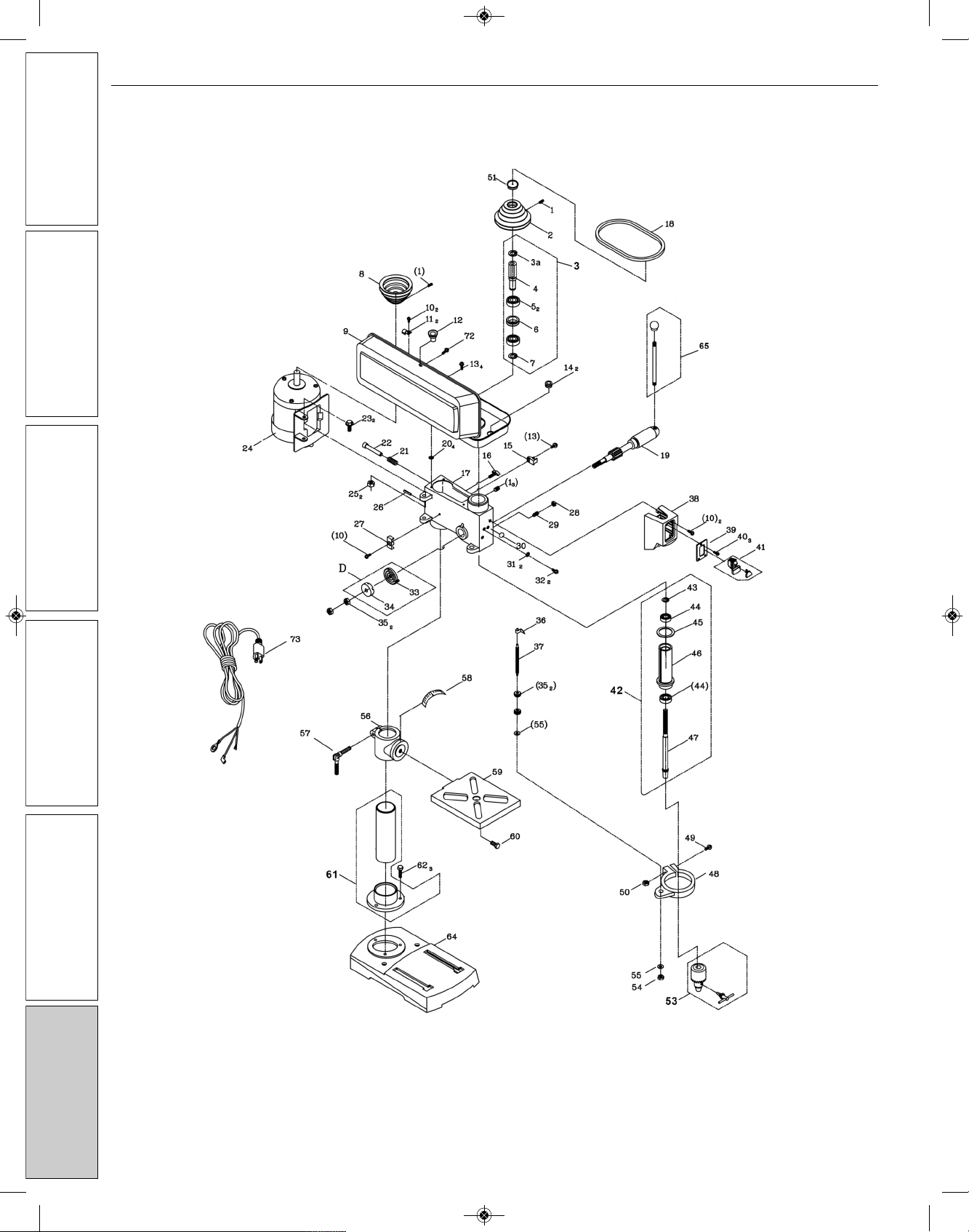
REPAIR PAR S ILLUS RA ION FOR 9680202 8˝ DRILL PRESS
GE ING S AR ED
SAFE Y / SPECIFICA IONS
ASSEMBLY / INS ALLA ION
OPERA ION
ROUBLESHOO ING
MAIN ENANCE / REPAIR
NOR E Operating Manual & Parts List 9680202
8
Replacement Parts Illustration for 8˝ Drill Press
9680202_oipm_En011_9640915.01 03/21/18 Page 8

NOR E Operating Manual & Parts List 9680202
GE ING S AR ED SAFE Y / SPECIFICA IONS ASSEMBLY / INS ALLA ION OPERA ION ROUBLESHOO ING MAIN ENANCE / REPAIR
9
REPAIR PAR S LIS FOR 9680202 8˝ DRILL PRESS
1 Hex screw 8 x 8mm *5
2 Spindle pulley 9639232.01 1
3 Upper spindle assy. (3a thru 7) 9639233.01 1
4 Pulley Insert NA 1
5 Ball bearing 6203RZ NA 2
6 Ring NA 1
7 Retaining ring NA 1
8 Motor pulley 9639212.01 1
9 Pulley cover 9639220.01 1
10 Philips screw 5 x 12mm *5
11 Washer 5mm *2
12 Pulley cover knob 9639236.01 1
13 Phillips screw 6 x12mm *5
14 Rubber bushing *2
15 Key holder 9642740.01 1
16 Lock knob 8 x 16mm 9639210.01 1
17 Head NA 1
18 V-Belt K690 9639213.01 1
19 Pinion shaft 9639208.01 1
20 Flat washer M6 *4
21 Compression spring 9639216.01 1
22 Motor stop 9639215.01 1
23 Hex screw 8 x 25mm *2
24 Motor 9639211.01 1
25 Nut 8mm *2
26 Spring pin 4 x 18mm 9639217.01 1
27 Block 9639235.01 1
28 Hex nut 8mm *1
29 Quill screw 8 x 14mm 9639609.01 1
30 Grounding label NA 1
31 Lock washer 5mm *2
32 Philips screw 5 x 8mm *2
34 Spring cap cover assembly 9639227.01 1
35 Hex nut 10mm *4
36 Pointer 9639250.01 1
37 Stop rod 10 x 1.5mm 9639249.01 1
38 Switch box 9639238.01 1
39 Switch plate 9639239.01 1
40 Philips screw ST4.2 x 10 *3
41 Switch 9608066.01 1
42 Lower spindle assembly (43 thru 47) 9639241.01 1
43 Nut NA 1
44 Ball Bearing 6201RZ NA 2
45 Rubber washer NA 1
46 Quill NA 1
47 Spindle shaft NA 1
48 Set ring 9639248.01 1
49 Philips screw 5 x 20mm *1
50 Hex nut 5mm *1
51 Seal 9639229.01 1
53 Chuck & key 9639240.01 1
54 Hex nut 6mm *1
55 Flat washer 6mm *2
56 Table support 9639245.01 1
57 Lock handle 9639247.01 1
58 Scale 9639246.01 1
59 Table 9639244.01 1
60 Hex bolt 12 x 25mm *1
61 Column & collar assembly 9639206.01 1
62 Hex bolt 8 x 25mm *3
64 Base 9639205.01 1
65 Feed handle assembly 9639207.01 3
70 Capacitor 16μF 250V 9640914.01 1
73 Power cable 9639218.01 1
∆ Operating Instructions & Parts Manual 9640915.01 1
Ref. Part
No. Description Number: Qty.
Ref. Part
No. Description Number: Qty.
(∆) Not shown.
(*) Standard hardware item, available locally.
(NA) Not available as replacement part.
9680202_oipm_En011_9640915.01 03/21/18 Page 9

NO ES
10
GE ING S AR ED
SAFE Y / SPECIFICA IONS
ASSEMBLY / INS ALLA ION
OPERA ION
ROUBLESHOO ING
MAIN ENANCE / REPAIR
NOR E Operating Manual & Parts List 9680202
9680202_oipm_En011_9640915.01 03/21/18 Page 10

11
NO ES
NOR E Operating Manual & Parts List 9680202
GE ING S AR ED SAFE Y / SPECIFICA IONS ASSEMBLY / INS ALLA ION OPERA ION ROUBLESHOO ING MAIN ENANCE / REPAIR
9680202_oipm_En011_9640915.01 03/21/18 Page 11

NOR E by C.H. Hanson warrants their products to be free of defects in material or workmanship. This
warranty does not cover defects due directly or indirectly to misuse, abuse, normal wear and tear, failure
to properly maintain the product, heated, ground or otherwise altered, or used for a purpose other than
that for which it was intended.
The warranty does not cover expendable and/or wear part (i.e. v-belts, screws, abrasives, jaws), damage to
tools arising from alteration, abuse or use other than their intended purpose, packing and freight. The
duration of this warranty is expressly limited to the terms noted below beginning from the date of
delivery to the original user.
The NOR E branded items carry the following warranties on parts:
All NOR E branded Tools and Accessories 1 YEAR
The obligation of NOR E by C.H. Hanson is limited solely to the repair or replacement, at our option, at its
factory or authorized repair agent of any part that should prove inoperable. Purchaser must lubricate and
maintain the product under normal operating conditions at all times. Prior to operation become familiar
with product and the included materials, i.e. warnings, cautions and manuals.
Failure to follow these instructions will void the warrant .
This warranty is the purchaser's exclusive remedy against C. H. Hanson for any inoperable parts in its
product. Under no circumstances is C. H. Hanson liable for any direct, indirect, incidental , special or
consequential damages including loss of profits in any way related to the use or inability to use our
products. This warranty gives you specific legal rights which may vary from state to state.
SERVICE & REPAIR
1. If a NOR E product requires a repair or warranty service DO NOT return the product to
the place of purchase.
2. All warranty related work must be evaluated and approved by NOR E.
3. Prior to returning any item the user must obtain factory approval and a valid RGA number.
4. For instructions and RGA number call toll free (800) 827-3398.
NORSE - a C.H. Hanson brand
2000 N. Aurora Rd., Naperville, IL 60563 U.S.A.
or call: 1-800-827-3398
NOR E Operating Manual & Parts List 9680202
NORSE Warranty
9680202_oipm_En011_9640915.01 03/21/18 Page 12
Table of contents
Other CH Hanson Power Tools manuals


Popular Power Tools manuals by other brands


WorkPro
WorkPro W125063AU Original operating instructions

Central Pneumatic
Central Pneumatic 65902 Set up and operating instructions

Sherman + Reilly
Sherman + Reilly SRK15X Operation manual

Thermaltronics
Thermaltronics TMT-HA200 user manual

Chef's Choice
Chef's Choice Diamond Hone 480 Series instructions

XTRONIC
XTRONIC 9010-PRO instructions