CH P1 User manual

Dear Valued Customer,
We are honored that you chose the P1 Dual Monaural Phono Stage for your audio system. Our team devoted their best efforts to
design and manufacture this to quality versatile and future- roof roduct and is roud to resent it to you. We ho e your P1
hono stage will bring you uncountable hours of emotion from your music collection.
But before you embark on your musical journey, we kindly request your attention to the information contained in this manual. The
P1, as you will discover in the following ages, is a Swiss recision roduct designed for ultimate erformance and flexibility.
However, reaching sonic excellence requires your unit to be set u and o erated correctly and this what this manual is all about. If
you have any questions or require assistance, lease don't hesitate to contact your authorized dealer.
We ho e you will enjoy your P1 hono stage for many years.
The Concert has just begun...
Cossy F.
Heeb T.
Rev 1.1 P1 User Manual 1

2 P1 User Manual Rev 1.1

Table of contents
1 Phono stage highlights........................................................................................................................................................ 5
1.1 In ut stage................................................................................................................................................................ 6
1.2 RIAA layback equalization......................................................................................................................................... 6
1.3 Voltage in ut im edance loading: hel ful guidance from your P1.................................................................................. 7
1.4 Careful metal work construction.................................................................................................................................. 7
1.5 Power su ly............................................................................................................................................................. 8
2 System Setu s.................................................................................................................................................................... 9
2.1 Dual Monaural setu .................................................................................................................................................. 9
2.2 True Monaural setu ................................................................................................................................................. 10
3 Read carefully before use.................................................................................................................................................. 11
3.1 Package content....................................................................................................................................................... 11
3.2 Safety notice............................................................................................................................................................ 11
3.3 Mains su ly............................................................................................................................................................ 12
3.4 Trans ort and ackaging........................................................................................................................................... 12
3.5 Cleaning.................................................................................................................................................................. 12
3.6 Maintenance and Servicing....................................................................................................................................... 12
4 Installation....................................................................................................................................................................... 13
4.1 Un acking............................................................................................................................................................... 13
4.2 Removing the trans ortation screw............................................................................................................................ 13
4.3 Positioning your unit................................................................................................................................................ 13
4.4 To covers................................................................................................................................................................ 14
5 Connections...................................................................................................................................................................... 15
5.1 Audio connections..................................................................................................................................................... 16
5.2 Ground connection................................................................................................................................................... 17
5.3 X1 o tional External Power Su ly connector............................................................................................................. 17
5.4 Ethernet ort............................................................................................................................................................ 17
5.5 Mains socket and voltage selection............................................................................................................................ 17
5.6 USB ort.................................................................................................................................................................. 17
6 O eration......................................................................................................................................................................... 18
6.1 Front anel.............................................................................................................................................................. 18
6.2 Front anel ush-buttons.......................................................................................................................................... 19
6.3 O erating modes...................................................................................................................................................... 19
6.3.1 Normal mode.................................................................................................................................................. 19
6.3.2 Shortcut Mode................................................................................................................................................. 21
6.3.3 Menu mode..................................................................................................................................................... 22
7 Unit menus....................................................................................................................................................................... 26
7.1 AUDIO SETTINGS menu............................................................................................................................................. 26
7.2 DISPLAY SETTINGS menu........................................................................................................................................... 27
7.3 SHORTCUTS menu..................................................................................................................................................... 28
7.4 FACTORY SETTINGS menu.......................................................................................................................................... 28
7.5 INSTALLED OPTIONS menu........................................................................................................................................ 29
7.6 NETWORK SETTINGS menu........................................................................................................................................ 29
8 Adjust the P1 to the cartridge............................................................................................................................................. 31
8.1 In ut ty e selection.................................................................................................................................................. 31
8.2 Initial loading selection............................................................................................................................................. 31
Rev 1.1 P1 User Manual 3

8.3 O timal gain selection.............................................................................................................................................. 31
8.4 Refined loading selection.......................................................................................................................................... 31
9 Firmware u date.............................................................................................................................................................. 32
9.1 Pre aring the USB Stick............................................................................................................................................ 32
9.2 U dating the unit's firmware.................................................................................................................................... 32
9.3 Emergency firmware u date rocedure...................................................................................................................... 32
10 Troubleshooting.............................................................................................................................................................. 33
11 S ecifications.................................................................................................................................................................. 34
4 P1 User Manual Rev 1.1
1 Phono stage highlights
CH roducts are roudly designed and manufactured in Switzerland by CH Precision Sàrl. Our engineers combined all their know-
how, ex ertise and ingeniousness to bring you the P1, a to erformance future- roof modular two channel hono stage with
Ethernet control ca abilities and USB flash-drive firmware u date. Like every CH Precision roducts, the P1 is versatile: two
configurations are ossible: Dual Monaural (the P1 holds the Left and Right channels in a single chassis) or True Monaural (two P1s
work together, each one rocessing a single channel, one hono stage board in each chassis). These configurations can be further
enhanced with the addition of one or two X1 External ower su ly units.
The P1 is a ure Class A discrete transistor based circuitry. This results is ultra low noise, high bandwidth and high slew rate
erformances. The signal stays in the analog domain all the way through.
The P1 rovides 3 in uts, two of which are in current mode, dedicated to MC cartridges. The third in ut is in voltage mode,
accommodating both MM and MC cartridges as well as ste -u transformers. The MC1 and MC2 current mode in uts require no
im edance matching. However, the MM/MC voltage mode in ut is fitted with a variable resistor seen by the connected cartridge as
a load for im edance matching. All the in uts have multi le gain settings.
The P1 holds the standard RIAA layback equalization filter. On to of it, a set of other EQ filters (EMI, Columbia, Teldec and
Decca) is available as an o tion that can be factory fitted or retrofitted to the unit.
A by assable subsonic high- ass filter can be inserted in the signal chain to remove unwanted rumble and very low frequency
noises.
The P1 uses tight tolerance, high-grade metal film resistors throughout the audio signal ath as well as custom high grade film
ca acitors in the filtering sections.
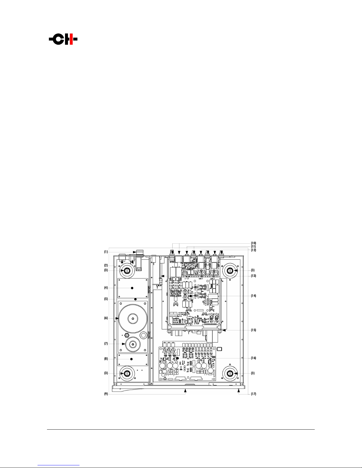
P1 main components
Rev 1.1 P1 User Manual 5

(1) External ower su ly in ut. For X1 o tional external ower su ly only
(2) Mains switch and ower cord rece tacle (on back anel)
(3) Adjustment shafts and screws
(4) Mains filter board
(5) Power su ly section
(6) Main ower transformer
(7) Standby ower transformer (ensures green mode standby)
(8) Front anel ower su ly board
(9) Dis lay (on front anel)
(10) Balanced and single-ended out uts
(11) XLR/RCA connectors for the MM/MC voltage in ut. Only the XLR or the RCA can be connected to a cartridge at a time
(12) XLR/RCA connectors for the two MC current in uts. For each in ut (MC1 and MC2), only the XLR or the RCA can be connected to a cartridge at a
time
(13) Control board (USB lug for firmware u date and Ethernet RJ-45 lug for control from Android A )
(14) Single-channel honostage board (one or two er unit)
(15) Back lane board
(16) Power su ly regulation board
(17) User interface ush-buttons
1.1 Input stage
Three in uts are available on the P1. Two of them are in current mode, dedicated to MC cartridges. The third in ut is in voltage
mode, accommodating both MM and MC cartridges as well as ste -u transformers.
MC1 and MC2 Current mode in ut: a current mode in ut reads the current generated by the cartridge (not its voltage).
Current mode in uts are usually dedicated to MC cartridges. The current from the cartridge is am lified by a discrete
transistor based trans-im edance am lifier. Using current mode in uts rovide a su erior signal to noise ratio com ared
to a conventional voltage in ut, better immunity and by essence no necessity to match im edance. The gain of the trans-
im edance am lifier is intrinsically de endent on the cartridge internal resistance. The lower the cartridge internal
resistance, the higher the gain. Multi le gain settings are available on each in ut to accommodate the variation of
resistance among cartridges.
MM/MC Voltage mode in ut: a voltage mode in ut reads the voltage generated by the cartridge. The voltage mode in ut
is used for all ty es of cartridges as well as with ste -u transformers. The cartridge out ut signal is am lified by a
voltage am lifier. The in ut is fitted with a user-variable resistive load (variable between 20 Ohms and 100 kOhms),
allowing to adjust the cartridge loading im edance and roviding a frequency res onse as flat as the setu will allow. In
order to assist the user to set u his system, the P1 comes with a feature that measures the frequency res onse of the
system (cartridge, cables and P1 in ut) and dis lays a series of gra hs showing the flatness of the system.
1.2 RIAA playback equalization
RIAA layback equalization is a s ecification for the layback of honogra h records. The P1 is fitted with a assive
im lementation of the RIAA equalization, using high grade, high tolerance metal film resistors and custom made film ca acitors.
The RIAA equalization rovides an accurate filtering for the layback of all the discs recorded with the RIAA equalization. However,
older records (u to the mid 50's and sometimes later) were recorded using different equalization. The P1 can be fitted with an
o tional board that contains 4 extra equalization filters: Columbia, EMI, Decca and Teldec. Please refer to your local dealer for
6 P1 User Manual Rev 1.1

more information about ordering or installing the o tional board into your P1 unit.
The enhanced RIAA curve: the unofficial Neumann time constant can be enabled by the user and is added to the RIAA equalization.
It is dis layed on the unit's screen with the letter "e" receding the standard filter: "eRIAA".
1.3 Voltage input impedance loading: help ul guidance rom your P1
Manufacturers often s ecify a recommended loading value or range that best matches their cartridge. This is the o timal
im edance that should electrically load the cartridge.
If an im edance of that value is sim ly added in arallel to the honostage in ut circuitry, sub-o timal result are often obtained.
The main reason is that the actual loading seen by the cartridge is the combination of the im edance of the cable, the in ut
im edance of the hono stage in ut and the variable loading that hono stage manufacturers usually rovide. Moreover, some
cartridge/tonearm airs can also exhibit resonance in the audio band, which can be seen as accidents ( eaks or di s) in the
frequency res onse. Such ringing can also be slightly tamed by ro er cartridge electrical loading.
In order to hel our customer to o timally load their cartridge, the P1 honostage comes with a 45 RPM test record. Side 1
contains a 250Hz-30kHz filtered ink noise track designed to be used in conjunction with a wizard available from the P1's menu.
The wizard allows to analyze the frequency res onse of the entire system (cartridge + tonearm + P1 in ut loading), while varying
the resistive loading of the P1's voltage in ut. Users can select to test the entire [20 Ohm – 100 kOhm] range that the P1
rovides, or any subset of that range for finer tuning. The P1 automatically acquires 21 different frequency res onse curves
a lying in ut loadings scattered across the range selected in the revious ste .
In addition to the frequency res onse curve for each loading value, an average level and a measurement of the flatness of each
curve (standard deviation) is also a rovided guidance.
As a general rule of thumb, user should start by analyzing the entire ossible loading range when a ste -u transformer is used, or
when no recommended loading is rovided by the cartridge manufacturer. If only a minimal loading value is defined, users are
welcomed to analyze all values above this s ecification. In other cases, one can start around the recommended value, roughly
from half to twice this value. Iterative calls of the loading wizard, while refining the analyzed range is recommended to find
o timal loading.
Pro er loading should meet the following criteria:
•Average level dro shouldn't exceed 2 to 3 dB com ared with the 100 kOhm loading setu
•Most extended frequency res onse
•Maximum flatness of the frequency res onse (flatness value should be as low as ossible)
Once a set of acquisitions is com leted, users can browse through analyzed loading values both visually (seeing the corres onding
frequency res onse curves) and sonically (listening to the effect of each loading value while laying any record).
1.4 Care ul metal work construction
The P1 hono stage chassis is made of high grade aluminum alloy with no visible screws on the front, to and side anels. First
class mechanical and chemical surface treatments rovide the luxury finish of the P1. Pin assembly of all chassis elements enables
smooth joints between metal arts while screws every 6cm ensure rotection against electromagnetic interferences.
Four stainless steel feet su ort the unit. Each foot is fitted with an elastomer ring to sit on delicate surfaces but is also equi ed
with height adjustable hardened steel s ikes to fine tune the unit osition. Horizontal leveling is accom lished using the rovided
screwdriver through the four adjustment shafts accessible from the to of the unit. Moreover, the steel s ikes serve as vibration
evacuation channels in a stack of units. S ecial covers are rovided to interface with the s ikes of the unit above (see section 4.4).
Rev 1.1 P1 User Manual 7

Vibrations from the u er unit is transmitted by the stacking cover to the shaft of the lower unit and from there to the lower unit's
feet or s ikes, forming a rivileged ath for vibrations evacuation.
1.5 Power supply
The ower su ly of the P1 is a linear su ly with multi le inde endent local regulation circuits.
The largest mains transformer is an oversized toroidal transformer and is used to su ly ower to the local regulation circuits,
which in turns, su ly both hono stage boards. The transformer also su lies ower to the digital areas of the unit (front anel
dis lay, microcontroller and Digital Signal Processing devices - DSP - that monitor the unit).
Discrete ultra low noise regulators are used throughout the ower su ly to ensure the urest low noise DC feed ossible to the
different audio sections. Each hono stage board enjoys dedicated analog regulators.
The second, smaller toroidal transformer inside the P1 is used as the Standby transformer to ensure green Standby mode, meeting
the latest energy saving regulations.
Both transformers have static shields between rimary and secondary windings. They are mounted on a steel late which is
isolated from the rest of the chassis by silent blocks to revent vibration transmission to the unit.
In ut AC voltage to the ower su ly can be set to 100V, 115V or 230V AC according to your local mains voltage.
8 P1 User Manual Rev 1.1

2 System Setups
The following setu s can be realized.
2.1 Dual Monaural setup
In this setu , a single P1enclosure is used to hold the Left and Right channels. Two boards are fitted inside its chassis, each one
inde endently rocessing a single channel. The mains ower su ly section is common to both the board, however se arate
dedicated DC regulation circuits are used for each board. For ultimate erformances, the X1 External Power Su ly unit should be
added to the setu .
Dual Monaural setup
Rev 1.1 P1 User Manual 9
L1 Preampli ier
Balanced XLR cables
P1 Phonostage
Turntable
XLR or RCA cables
XLR or RCA cables

2.2 True Monaural setup
In this setu , two P1s enclosures are used to hold a single channel each (Left res ectively Right). The entire ower su ly of each
P1 is dedicated to one channel, further enhancing the system erformances. Both P1s should be connected to a network via a
router to ensure all audio settings (such as gain, selected in ut, cartridge laoding) are synchronized between units. For ultimate
erformances, u to two X1 External Power Su ly unit should be added to the setu .
True Monaural setup
10 P1 User Manual Rev 1.1
Balanced XLR cables
Turntable
P1 Right True Monaural Phonostage P1 Le t True Monaural Phonostage
L1 Right True Monaural Preampli ier L1 Le t True Monaural Preampli ier
Balanced XLR cables
XLR or RCA cables
XLR or RCA cables
Router with DHCP server
RJ45 Ethernet cables

3 Read care ully be ore use
Please read this manual carefully before making connections or o erating your P1 hono stage. After reading this manual, lease
store it in an accessible lace for future reference. If, after reading this manual, you feel unsure about how to make connections or
how to o erate the unit, lease contact your authorized dealer for assistance.
3.1 Package content
Make sure that the ackage content is com lete. If not, lease contact your authorized dealer. Your ackage contains:
The P1 hono stage unit
A ower cord
4x adjustment steel s ikes
2x 4mm banana lugs
An accessory box containing:
◦A s ike adjustment screwdriver
◦4x aluminum to covers
◦4x steel stacking covers
Please store the ackaging for future use. Check your P1 hono stage for any a arent damage. In case of a damage, lease
contact your authorized dealer. If your P1 hono stage is still very cold due to trans ort, lease let it warm u to room
tem erature in order to avoid condensation inside the unit.
3.2 Sa ety notice
Make sure to observe the following rules:
Always kee the unit horizontal when handling it
Install your P1 hono stage on a stable base
Do not install your P1 hono stage near water
Always handle with care. The P1 hono stage is fairly heavy, so have someone to hel you when moving it around
Do not ex ose the unit to any kind of liquid
Do not install it under direct sunlight or near any heat source such as radiators or other a aratus generating heat
Do not install it in a confined s ace and make sure there is sufficient airflow around the unit, including under the unit.
Do not o erate under high ambient tem erature (>40°C) or in extremely high humidity conditions
Only use o tions and accessories s ecified or recommended by CH Precision
Do not o en the unit nor try to service it by yourself. Always refer to a qualified technician for service, maintenance or
u grades. Failure to do so will void the unit's warranty
Rev 1.1 P1 User Manual 11

3.3 Mains supply
Before connecting the mains ower cord, make sure that the mains voltage selection at the back of the unit matches your local
mains voltage.
Make sure your P1 hono stage is disconnected from the AC wall socket in the following cases:
When cleaning the unit
During thunderstorms
When unused for a long eriod of time
Also make sure your P1 hono stage is turned off when making audio connections (it is also recommended to turn off the rest of
the system).
3.4 Transport and packaging
The P1 hono stage must always be stored in its original ackaging for trans ortation. Doing so will ensure an o timal level of
rotection for your unit. Please kee all ackaging in a dry and clean lace for future use.
Very im ortantly, the trans ortation screw at the bottom of the unit must be fitted rior to trans ortation to avoid internal
damage. Please refer to section 4.2 for further details.
Finally we recommend to remove the adjustment s ikes and to ut them in the ackaging box rior trans ortation. Vibrations
during trans ort may cause the adjustment s ikes to move from their retracted osition; there could be a risk of damaging the
iece of furniture the unit is installed onto if the s ikes are not fully retracted.
3.5 Cleaning
Use a soft, dry cloth for cleaning. Never use any solvent or liquids as they may damage the surface or infiltrate the unit. Please
use an ultra-soft iece of fabric designed to clean eyeglasses for the front dis lay area.
3.6 Maintenance and Servicing
The P1 hono stage contains no user serviceable arts. Do not try to o en, modify or re air your P1 by yourself. This will void any
warranty. Your P1 hono stage must be checked by a qualified technician in any of the following cases:
The unit is malfunctioning
The ower cord or mains lug at the back of the unit is damaged
The unit was dro ed to the floor or resents external damage
The P1 hono stage has been ex osed to liquids or unknown substances
12 P1 User Manual Rev 1.1

4 Installation
4.1 Unpacking
Un ack your P1 hono stage and store the ackaging for future use. The P1 hono stage is fairly heavy, so have someone to hel
you when removing it from its ackaging.
4.2 Removing the transportation screw
The transformers must be secured during trans ortation to avoid internal damage. The trans ortation screw is located at the
bottom of the unit. Always kee the unit horizontal while fitting or removing the trans ortation screw.
Security screw location
(1) Trans ortation screw. Must be fitted for trans ort and should be removed during installation
4.3 Positioning your unit
Position the P1 unit on a stable and sturdy base. Make sure air is able to flow freely around the unit.
For best transmission and immunity to external vibration noise, CH Precision recommends to rest the P1 on the rovided steel
s ikes. Insert a s ike into each foot. Please use the rovided screwdriver to screw the s ikes into the feet and make the level
adjustments.
O tional CH su ort discs have been designed to o timally cou le the s ikes with the rack on which the P1 sits, simultaneously
ensuring vibration su ression as well as decou ling from external vibration sources. Please refer to your local dealer for more
information on the CH Su ort Discs.
Rev 1.1 P1 User Manual 13

Adjustment sha ts, eet and spikes
(1) Adjustment shafts. Insert the adjustment s ikes and use the rovided screwdriver to secure and adjust individual s ikes
(2) Feet
(3) Adjustment s ike heads (when inserted into the adjustment shafts)
(4) Adjustment s ike
4.4 Top covers
Two ty es of to covers are delivered with your P1 unit. The steel stacking covers are used when several CH units are stacked on
to of each other. The aluminum to covers are used for decorative ur oses only, either for the to unit of stacked units or for
each unit otherwise. Do not stack any com onent other than CH's on your P1 nor use the aluminum to covers in the middle of a
stack of units.
Sha t covers (le t: stacking cover, right: top cover)
14 P1 User Manual Rev 1.1
5 Connections
This section rovides information on how to connect your P1 hono stage to the rest of your system. Please connect your P1 in the
same order as this cha ter describes, starting with the audio connections and ending with the mains connections.
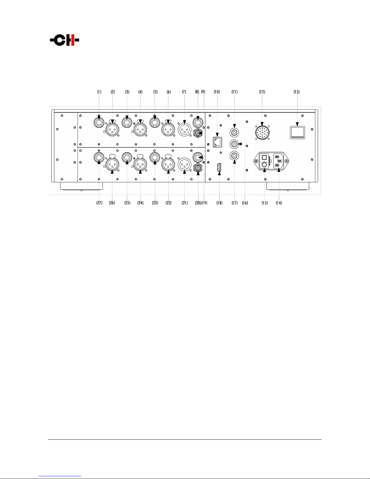
P1 rear panel connections
(1) RCA left MC1 current mode in ut
(2) XLR left MC1 current mode in ut
(3) RCA left MC2 current mode in ut
(4) XLR left MC2 current mode in ut
(5) RCA left MM/MC voltage mode in ut
(6) XLR left MM/MC voltage mode in ut
(7) XLR left out ut
(8) RCA left out ut
(9) BNC left out ut
(10) Ethernet ort for command interface
(11) Analog ground connector 1.Can be connected to a tonearm's ground wire using rovided jum er banana ada ter
(12) External ower su ly connector for X1 ower su ly o tion
(13) Power on/off switch
(14) Power cord rece tacle
(15) Power fuse and voltage selection
(16) Analog ground connector 2.Can be connected to a tonearm's ground wire using rovided jum er banana ada ter
(17) Earth connector. Internally connected to digital ground
(18) USB ort for software u dates
(19) RCA right out ut
(20) BNC right out ut
(21) XLR right out ut
(22) XLR right MM/MC voltage mode in ut
(23) RCA right MM/MC voltage mode in ut
Rev 1.1 P1 User Manual 15

(24) XLR right MC2 current mode in ut
(25) RCA right MC2 current mode in ut
(26) XLR right MC1 current mode in ut
(27) RCA right MC1 current mode in ut
5.1 Audio connections
The P1 unit is com osed of two identical hono stage boards, either located in one (Dual Monaural setu ) or in two se arate
enclosures (True Monaural setu ). Each board rocesses one audio channel (Left res ectively Right channel). The way to connect
the P1 to your turntable will de end on the ty e of cartridge you intend to use.
Each channel contains 3 in uts. Two of them are in current mode while the third one is in voltage mode (see section 1.1for more
details). For ease of use and convenience, each in ut has two ty es of connectors, XLR and RCA. Both connectors are in arallel,
therefore only one connector er in ut must be used at any one time. However the three in uts are totally inde endent from each
other, allowing u to three different cartridges to be connected at all times.
The MC1 and MC2 current in uts are mainly dedicated to MC cartridges. Although connecting an MM cartridge to a
current in ut will do no harm to the cartridge nor the P1 in ut, the overall gain achieved in the hono stage will robably
be too low, even with the P1 gain set to maximum. The gain of a current in ut is inversely ro ortional to the cartridge's
internal resistance: the lower the internal resistance, the higher the gain. MC cartridges have an intrinsic low resistance
and will therefore work well on a current in ut. On the other hand, most MM cartridges have a too high internal
resistance and will therefore be best suited to the voltage in ut. Besides, current in uts don't require any cartridge
im edance loading, sim lifying the system setu .
The MM/MC voltage in ut can be used with all ty es of cartridges as well as with ste -u transformers. On a voltage
in ut, im edance loading is crucial to counteract the undesired effects a cartridge (and the associated interconnections)
read in voltage mode will exhibit. The aim is to achieve a frequency res onse (am litude of the signal versus frequency)
as flat as ossible (the am litude variation between signals of different frequencies is minimal). The P1 voltage in ut
rovides a selection of over five hundred resistance values one can choose from, as high as 100 kOhms and down to 20
Ohms. As adjusting a frequency res onse isn't a trivial o eration, the P1 features an internal measurement system
combined with a DSP (Digital Signal Processing) device that analyzes and dis lays the frequency res onse of the system
to hel the user select o timum loading based on objective criteria (measurement and analysis of frequency res onse) as
well as subjective references (one can also listen to the real-time effect of changing the cartridge loading on-the-fly).
The loading can be freely modified at any time from the user interface. Besides, as the voltage in ut holds two
connectors (XLR and RCA) in arallel, one could take advantage of the unused connector to add any desired (including
non-resistive) loading de ending on the system conditions and one's sound ersonal tastes. On the RCA, the loading
would be a lied between ti and ring while it would be a lied between ins 2 and 3 of the XLR.
The P1 out ut stage is equi ed with both balanced and single-ended ty es of connections, XLR, RCA and BNC. The high
bandwidth, ultra low noise and distortion discrete am lifier rovides an ideal connection to the downstream unit. We
recommend that the out ut stage doesn't get loaded with an im edance lower than 10 kOhms (the in ut im edance of
the unit connected to the P1 should be greater than 10 kOhms). If for exam le the P1 is connected to an L1 ream lifier,
it is recommended to set the L1 im edance to High-Z on the in ut the P1 is connected to.
16 P1 User Manual Rev 1.1

5.2 Ground connection
The back anel of the P1 unit is fitted with 4mm banana sockets. The black sockets are connected to audio ground while the yellow
and green socket is connected to mains earth. These sockets can be used to connect the ground of the turntable. Ex erimentation
will define which socket to use. A cou le of banana lugs are rovided with the P1 unit. The ground lead from the turntable can be
screwed to the banana lugs which in turns can be inserted into the back anel sockets.
5.3 X1 optional External Power Supply connector
This connector allows to connect the X1External Power Su ly unit. A custom made interconnect cable delivered with the X1 unit
lugs into this connector, allowing to reach the next ste in ower su ly regulation. The P1 unit detects at ower u that the X1 is
connected and leaves its mains section off and uses to the X1 ower su lies instead. Please note that the P1 AC mains socket must
still remain lugged to the AC wall socket.
5.4 Ethernet port
The Ethernet ort is used in the following instances:
To control the P1unit settings via the CH Control Android A running on your tablet. Sim ly connect the P1 Ethernet ort
to a standard Ethernet Router (equi ed with a wireless access oint so it can talk to the tablet) using an Ethernet RJ45
Category 5 cable or better. Using the CH Android A , the P1 settings can be accessed and adjusted on the fly.
In the True Monaural setu (see cha ter 2.2), two P1 enclosures are used. In order for the units to automatically a ly
the same settings to both channels, the two units must be connected to each other. The sim le method is to use an
Ethernet crossover cable and connect both Ethernet orts together. Both units are arranged in a Master and Slave
configuration defined in the user interface menus (see section 7.6 for more details).
Both above oints can be combined in case of a True Monaural setu where one also wants to control the units via the CH
Control A . In this configuration both P1units should be connected to a router (equi ed with a wireless access oint so
it can talk to the tablet). Both units are arranged in a Master and Slave configuration defined in the user interface menus
(see section 7.6 for more details)
5.5 Mains socket and voltage selection
Make sure that the voltage selector at the back of the unit is set to the correct mains voltage with res ect to the AC voltage at your
location. Connect the ower cord to the unit's mains socket and the ower cord's lug to a wall socket.
5.6 USB port
The P1 unit runs a firmware that defines the unit's o eration. The USB ort is used to erform u date to the P1 unit's firmware.
The firmware u date is carried out via a USB stick containing the newer version of firmware. The USB Stick is inserted at the back
of the unit into the USB ort and the u date start command is activated via the front anel user interface.
Please note that the USB ort has no other ur oses than to u date the P1 unit firmware. For more information on unit firmware
u date, lease refer to section 9 of this manual.
Rev 1.1 P1 User Manual 17
6 Operation
The P1 hono stage is o erated either from the unit's front anel or from a tablet using the CH Control A .
6.1 Front panel
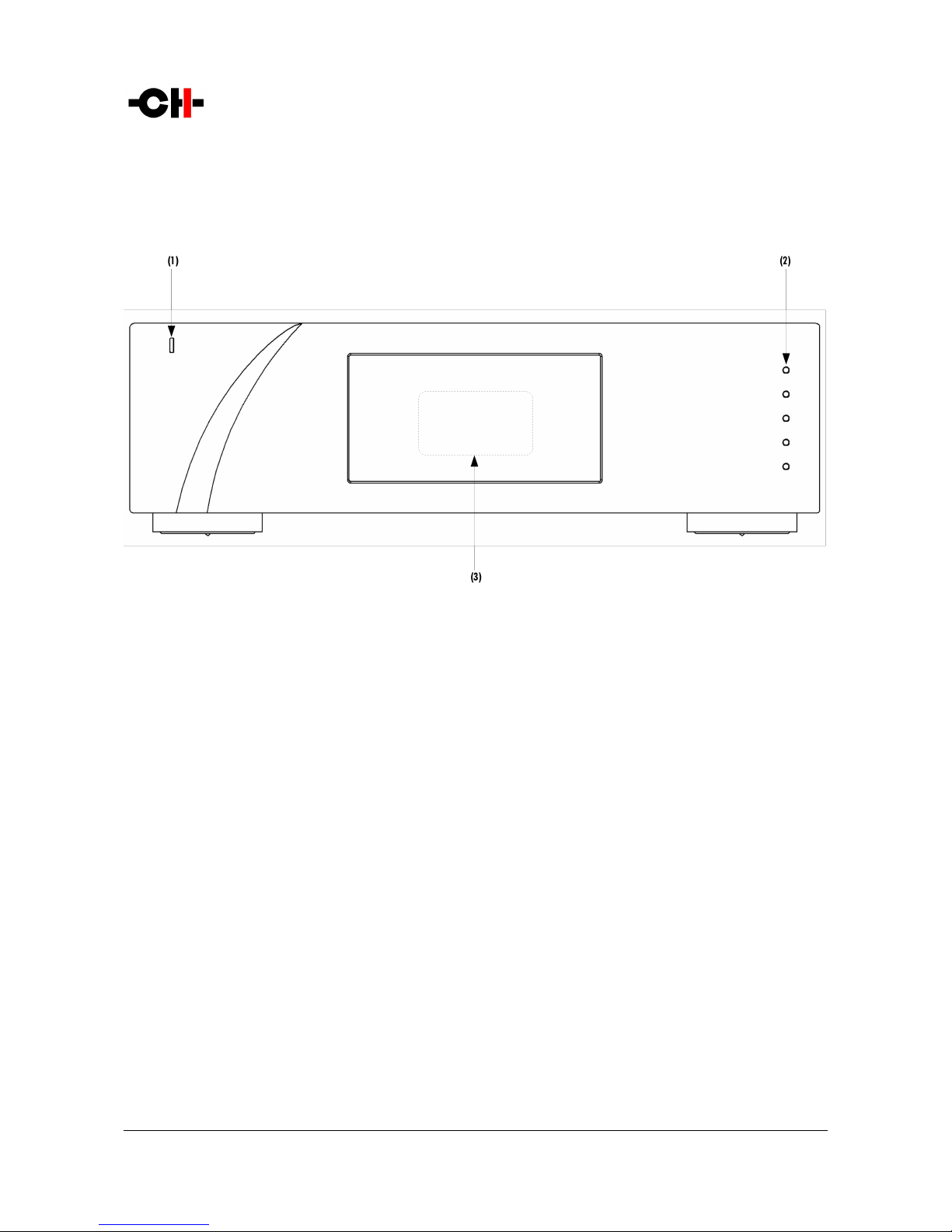
Front panel elements
(1) Standby LED
(2) Five user control ush-buttons
(3) Dis lay area (high-definition dis lay)
The standby LED lights u when the unit is in standby. It is turned off by default during o eration and shortly lights u whenever it
receives an IR remote control command. The LED can also be rogrammed to remain ON during o eration. The dis lay is a high-
definition anel with very wide viewing angle, high contrast and high brightness ensuring o timal reading comfort. The color and
brightness of the dis lay can be configured to one's taste.
18 P1 User Manual Rev 1.1
6.2 Front panel push-buttons
The ush-buttons located on the front anel of the P1 unit allow the user to access the unit's settings through a series of menus.
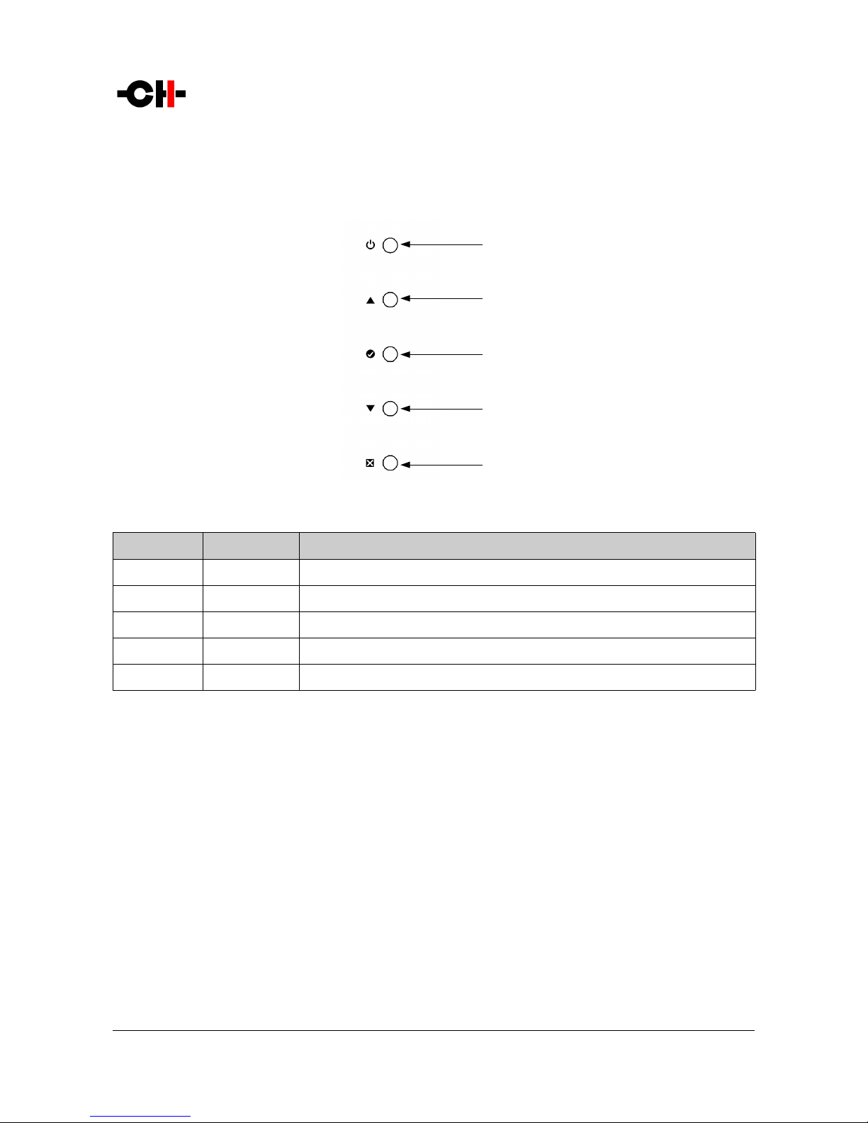
Front panel push-buttons
Button number Button symbol Descri tion
1SStandby (long ush) / Mute/Unmute (short ush)
2NU
3ROK
4ODown
5QCancel
Front panel push-buttons description
6.3 Operating modes
The P1 hono stage has three o erating modes: Normal mode, Shortcut modes and Menu mode. Normal mode is used to access the
main P1 controls whereas Menu mode is used to fully configure the unit. Shortcuts mode is designed for quick access to selected
Menu mode items. Shortcuts are user rogrammable and most Menu mode items can be selected as Shortcuts.
6.3.1 Normal mode
Normal mode is used for standard honostage functions. When owered-on, the P1starts in Normal mode. The dis lay looks as
follows:
Rev 1.1 P1 User Manual 19
(2)
(3)
(4)
(5)
(1)
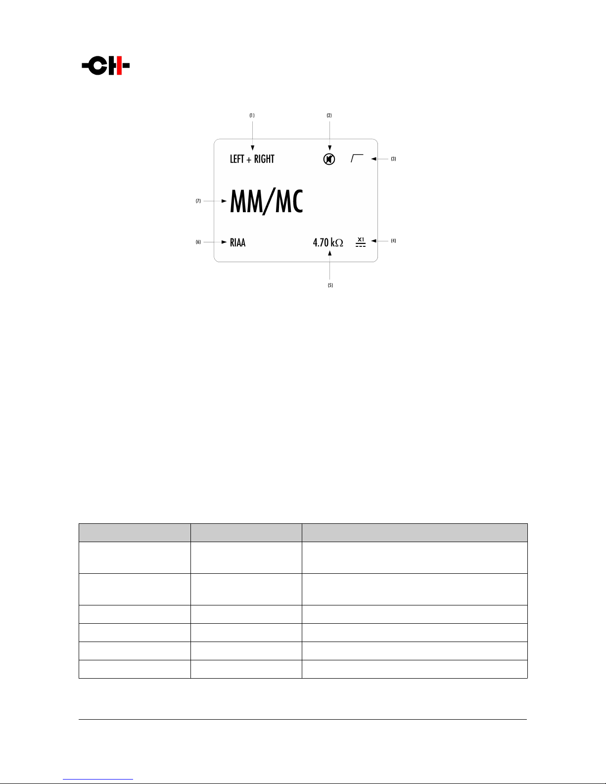
Normal mode display elements
(1) Handled channel (in true monaural) or channel air (in dual monaural)
(2) Mute indication. If the 7 symbol is resent, the out ut is muted
(3) Subsonic filter indication. If the / symbol is resent, the subsonic filter is engaged
(4) External ower su ly indication. When an external ower su ly is connected and engaged, < symbol is dis layed and internal ower su ly is
turned off
(5) Cartridge loading indication (only for voltage mode MM/MC in ut)
(6) Equalization curve engaged
(7) Selected in ut source. Each in ut source can be renamed through P1's menu
Dis layed elements de end on the user settings. In the exam le above, an X1- owered P1 is set as a dual-monaural hono stage,
MM/MC voltage mode in ut is selected. The RIAA equalization curve is selected, the subsonic filter is engaged and a 4.7 kOhm
loading is a lied to the cartridge. The P1 is muted.
Following table shows the actions of the front anel ush-buttons in Normal mode.
Front face ush buttons Unit State Unit Action
S, short ush STANDBY
Any other state
Wake from STANDBY
Mute/Unmute
S, long ush STANDBY
Any other state
Wake from STANDBY
Go to STANDBY
NAny state Selects next in ut
RAny state Enter Shortcuts mode
OAny state Selects revious in ut
QAny state No effect
Push-buttons actions in Normal mode
20 P1 User Manual Rev 1.1
Table of contents
Other CH Recording Equipment manuals


