chadwick 1677-2 User manual

Chadwick
Engineering Ltd.
TITAN
T
RAINER
E
QUINE
T
READMILL
MODEL 1677-2
USER’S MANUAL
INSTALLATION –OPERATION -MAINTENANCE
Publication Number: 1760-260-R1
Chadwick Engineering Ltd.
633 Norris Court
Kingston, Ontario - Canada - K7P 2R9
www.chadwickengineering.com
Sales and Customer Support
(613) 384-2866

June 5, 2012
Chadwick Engineering Ltd.
TITAN Trainer Equine Treadmill
Model 1677-2
Publication No 1760-260-R1
Chadwick Engineering Ltd. -
TITAN Trainer
Model 1677-2
Installation – Operation – Maintenance
Page 2 of 33
TABLE OF CONTENTS
1.0
TITAN TRAINER
OVERVIEW...........................................................................................................4
1.1 FEATURES ........................................................................................4
1.2 SPECIFICATIONS................................................................................5
2.0 SAFETY .............................................................................................................................................5
2.1 OPERATOR SAFETY ............................................................................5
2.2 HORSE SAFETY .................................................................................6
3.0 TRAINER INSTALLATION & SETUP...............................................................................................7
3.1 MECHANICAL INSTALLATION .................................................................7
3.2 ELECTRICAL INSTALLATION ..................................................................7
3.3 OPERATOR INTERFACE SETTINGS .........................................................8
3.4 BELT LUBRICATION........................................................................... 10
3.5 INCLINE SETUP................................................................................ 12
3.6 USB FUNCTIONS.............................................................................. 13
3.7 MOTOR AMPS.................................................................................. 14
3.8 MILES RUN ..................................................................................... 15
4.0 TRAINER OPERATION...................................................................................................................15
4.1 EMERGENCY STOP ........................................................................... 16
4.2 CONTROL POWER ............................................................................ 16
4.3 ALARMS ......................................................................................... 16
4.4 CYCLE MODES................................................................................. 17
4.4.1 Manual Cycle.........................................................................................................................18

June 5, 2012
Chadwick Engineering Ltd.
TITAN Trainer Equine Treadmill
Model 1677-2
Publication No 1760-260-R1
Chadwick Engineering Ltd. -
TITAN Trainer
Model 1677-2
Installation – Operation – Maintenance
Page 3 of 33
4.4.2 Auto Cycle.............................................................................................................................21
5.0
TITAN TRAINER
PROGRAM MANAGEMENT..............................................................................25
5.1 HORSE NAME CONFIGURATION ........................................................... 25
5.2 TRAINING PROGRAM CONFIGURATION .................................................. 26
6.0
TITAN TRAINER
MAINTENANCE ................................................................................................28
6.1 ADJUSTMENTS................................................................................. 28
6.2 CLEANING ...................................................................................... 28
6.3 LUBRICATION .................................................................................. 29
6.4 HYDRAULIC POWER SUPPLY............................................................... 29
7.0
TITAN TRAINER
REPORT TOOL INSTALLATION .....................................................................30
7.1 SYSTEM REQUIREMENTS: .................................................................. 30
7.2 INSTALLATION ................................................................................. 30
7.3 UN-INSTALLATION ............................................................................ 30
8.0
TITAN TRAINER
REPORT TOOL.................................................................................................30
8.1 LOG SUMMARY ................................................................................ 31
8.2 USB UPLOAD .................................................................................. 32
8.3 MAINTENANCE................................................................................. 33
8.4 BACKUP DATABASE .......................................................................... 33
8.5 EXIT REPORT TOOL.......................................................................... 33
8.6 ABOUT........................................................................................... 33
9.0 WARRANTY ....................................................................................................................................33
10.0 PARTS LIST ......................................................................... ERROR! BOOKMARK NOT DEFINED.
11.0 ELECTRICAL SCHEMATICS............................................... ERROR! BOOKMARK NOT DEFINED.

June 5, 2012
Chadwick Engineering Ltd.
TITAN Trainer Equine Treadmill
Model 1677-2
Publication No 1760-260-R1
Chadwick Engineering Ltd. -
TITAN Trainer
Model 1677-2
Installation – Operation – Maintenance
Page 4 of 33
1.0
TITAN Trainer
Overview
The
TITAN Trainer
is a robust treadmill for equine performance training and rehabilitation. The wide
treadmill belt and see-through side panels coupled with the operator friendly control system and safety
devices make this equine treadmill a valuable tool for any horse owner, trainer or equine veterinary clinic.
1.1 Features
The
TITAN Trainer Equine Treadmill
features include:
Variable speed 0 to 15 MPH
Variable incline 0 to 8.0 Degrees.
Wireless Heart Rate Monitoring System
Automatic Belt Lubrication System
User friendly controls with LCD Colour Touch Screen display
Selection and storage of up to 40 Horse Names
Selection and storage of 20 User Configured Programs
Data Logging including Program Number, Horse Name, Speed, Incline, Heart Rate
Safety Stop System – Emergency Stop Pushbutton , Safety Strap and Stumble Sensor
Steel Construction with Corrosion Resistant Paint System
Durable Transparent Polycarbonate Side Panels
Energy Absorbing Deck
Durable Non-slip Mini-Cleat Belting on Ramps
Durable Long Life Belt
Spring Lift Assist on Entry Ramp (for cleaning)
Stainless Steel Hardware
UHMW Polyethylene Hoof Guards

June 5, 2012
Chadwick Engineering Ltd.
TITAN Trainer Equine Treadmill
Model 1677-2
Publication No 1760-260-R1
Chadwick Engineering Ltd. -
TITAN Trainer
Model 1677-2
Installation – Operation – Maintenance
Page 5 of 33
1.2 Specifications
Overall Dimensions (with ramps) 20’-9”L x 6’-4”W x 6’-7”H
Deck Dimensions 3’ Wide x 10’ Long
Height (above deck) 5’-2”
Weight 3500 lbs
Speed 0 to 15 mph
Incline 0 to 8 deg
Belt Drive Motor 10 HP
Incline HPU Motor 1 HP
Electrical Power 208 - 230 VAC, 1 Ph, 50 Amp.
Ambient Operating Temperature 5 to 40 ºC
2.0 Safety
2.1 Operator Safety
As always, when working with horses, care must be taken so that neither
the handler nor the horse is put in an unsafe position especially around new
unfamiliar equipment.
CRUSHING HAZARD !!
The
TITAN Trainer
is powered to an incline position (maximum angle is
8 degrees). At no time shall anything be placed under the machine since it
could be crushed when the machine returns to the level position. In
Automatic Mode, the frame UP/DOWN motion is controlled by the program,
i.e. not initiated by the operator. In the case of an Emergency Stop, the
treadmill belt will stop and the incline will not change. Once the E-stop is
reset and the power is reapplied the treadmill will return to its level position.
This crushing hazard could result in serious injury or death. Special care
shall be taken to keep children away from this machine when it is powered!!!

June 5, 2012
Chadwick Engineering Ltd.
TITAN Trainer Equine Treadmill
Model 1677-2
Publication No 1760-260-R1
Chadwick Engineering Ltd. -
TITAN Trainer
Model 1677-2
Installation – Operation – Maintenance
Page 6 of 33
PINCH HAZARD !!
The treadmill belt can travel at high speeds and is powered by a high
torque gear motor. This moving belt creates a pinch hazard as it passes
around the rolls and close to the treadmill floor at the entry end of the
treadmill. Serious injury can result if fingers or toes become trapped at
these pinch points. For this reason, the treadmill is not intended for human
use. Special care shall be taken to keep children away from this machine
when it is powered!!!!
ELECTRICAL SHOCK !!
Before opening any electrical enclosures, ensure that the power is
disconnected. Electrical shock can cause serious injury or death.
2.2 Horse Safety
Special care has been taken with the
TITAN Trainer
to minimize any
potential hazards for the horse. The wide ramps are covered with a non-slip
cleated belting to provide the horse with a sure-footed grip. No sharp edges
or corners are exposed where the horse could be injured. A horse shall not
be left unattended on the treadmill.
A tail strap restrains the horse from backing out of the treadmill. If the
tension in the tail strap becomes too high, the strap releases and the
treadmill stops. The tail strap release tension can be adjusted so that more
or less strap tension will cause the strap to release and the treadmill to stop.
The manual tail strap release on the left side of the machine can be
actuated even under high strap tension.

June 5, 2012
Chadwick Engineering Ltd.
TITAN Trainer Equine Treadmill
Model 1677-2
Publication No 1760-260-R1
Chadwick Engineering Ltd. -
TITAN Trainer
Model 1677-2
Installation – Operation – Maintenance
Page 7 of 33
The horse must be cross-tied to its halter to be restrained from moving
forward. The cross-ties should keep the horse close to the tail strap to
minimize the possibility of a horse kicking over the strap and causing injury.
In the rare case that the horse was to stumble and fall, a stumble sensor
photo-beam will stop the treadmill immediately. The sensor must be
blocked, i.e. the horse standing on the treadmill, breaking the photo beam,
in order for the treadmill to be started and the beam must remain blocked at
all times during any cycle or the treadmill belt will stop.
3.0 Trainer Installation & Setup
3.1 Mechanical Installation
The
TITAN Trainer
is delivered fully assembled. It must be placed on a level concrete floor or pad.
Once the treadmill is in position, leveling feet on the frame at the entry end must be adjusted so that both
leveling feet and the front incline rollers are in firm contact with the floor. After adjusting the feet, the
locking nuts must be tightened to lock the adjustment screws in the position. Position the manure
collection pan under the belt at the entry end and lower the entry and exit ramps. If both ramp wheels do
not contact the floor, the ramp hinge attachment bolts can be loosened and the ramp adjusted.
3.2 Electrical Installation
The
TITAN Treadmill
comes complete with all electrical wiring intact. Provisions for power supply
connection have been included complete with a 3 meter cord and plug attachment (pre-installed) rated for
50amps. Also supplied loose is the 50amp rated mating receptacle. This receptacle must be installed by
the user. Please refer to local electrical codes to determine receptacle installation method and location
requirements. A 50amp, 208-230VAC, 1Ø power supply circuit is required. This circuit must be protected
at the source with short circuit and thermal protection as per local authority electrical requirements.
June 5, 2012
Chadwick Engineering Ltd.
TITAN Trainer Equine Treadmill
Model 1677-2
Publication No 1760-260-R1
Chadwick Engineering Ltd. -
TITAN Trainer
Model 1677-2
Installation – Operation – Maintenance
Page 8 of 33
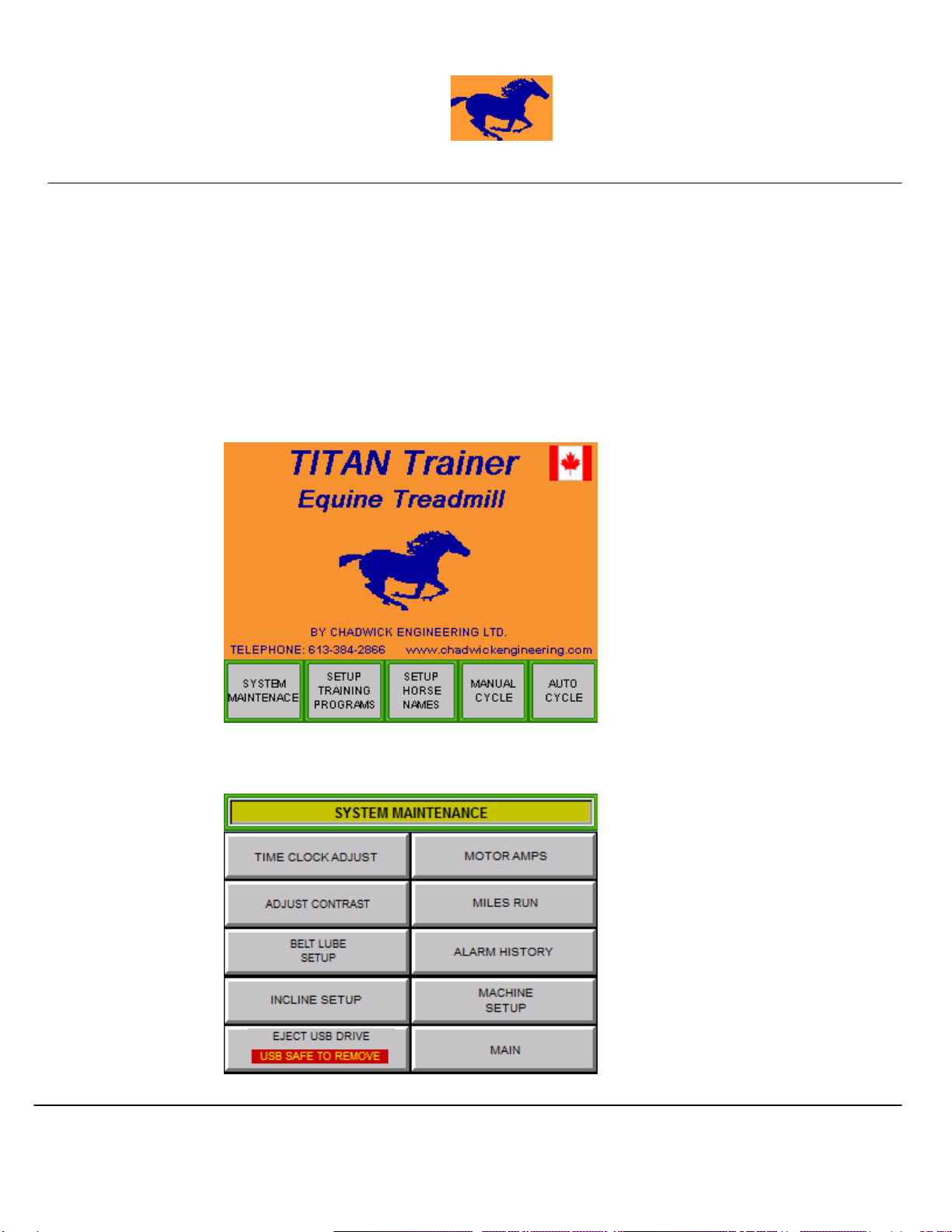
3.3 Operator Interface Settings
The trainers’ operator interface requires initial setup up of the following:
Contrast Adjustment
Clock Adjustment – Hour Only
To reach the initial setup press the ‘SYSTEM MAINTENANCE’ button from the main screen. The
‘SYSTEM MAINTENANCE’ screen will be displayed. Select the desired setup screen.
Main Screen
June 5, 2012
Chadwick Engineering Ltd.
TITAN Trainer Equine Treadmill
Model 1677-2
Publication No 1760-260-R1
Chadwick Engineering Ltd. -
TITAN Trainer
Model 1677-2
Installation – Operation – Maintenance
Page 9 of 33
System Maintenance Screen
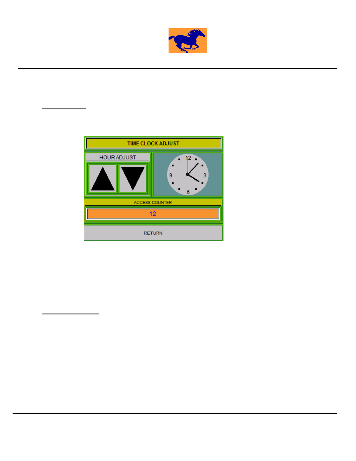
PLC DATE/TIME
To access the system date and time settings of the touch screen, from the ‘SYSTEM MAINTENANCE’
screen press the ‘PLC DATE/TIME’. Below depicts the adjustment screen.
To adjust the time, press the adjustment field (fields with black background). A keypad entry screen
will appear. Enter the desired field parameters ie. for YEAR/MONTH such as December of 2012 enter
‘1212’. When all fields are adjusted as required press the corresponding Update pushbutton to initiate the
change.
The ‘Access Code’ number is for manufacturer use only. No adjustment to this code can be made by
the user.
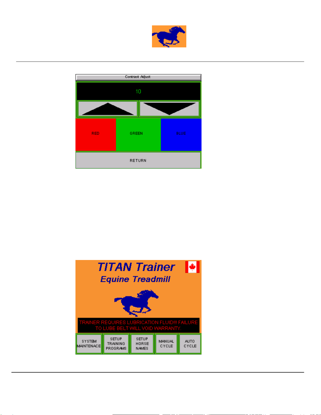
ADJUST CONTRAST
To access the colour and brightness settings of the touch screen, from the ‘SYSTEM MAINTENANCE’
screen press the ‘ADJUST CONTRAST’. Below depicts the adjustment screen.
June 5, 2012
Chadwick Engineering Ltd.
TITAN Trainer Equine Treadmill
Model 1677-2
Publication No 1760-260-R1
Chadwick Engineering Ltd. -
TITAN Trainer
Model 1677-2
Installation – Operation – Maintenance
Page 10 of 33
Contrast & Time Setup Screen
To adjust the time, use the corresponding arrow keys to increment or decrement the hour. The hour is
the only time maintenance function adjustment available.
To adjust the contrast, use the corresponding arrow keys. Adjustment levels from 1 to 7 can be made.
The red-green-blue bars show what these colours will look like at the current contrast adjustment level.
3.4 Belt Lubrication
The
TITAN Trainer
comes with an automatic Belt Lubrication System (BLS). The BLS is equipped
with a lubrication fluid low level detector and an automatic belt lube spray pump. If the lubrication fluid in
the reservoir reaches a low level the following message will appear on the main screen as depicted below.

June 5, 2012
Chadwick Engineering Ltd.
TITAN Trainer Equine Treadmill
Model 1677-2
Publication No 1760-260-R1
Chadwick Engineering Ltd. -
TITAN Trainer
Model 1677-2
Installation – Operation – Maintenance
Page 11 of 33
Main Screen
The automatic belt lubrication cycle settings can be adjusted from the Belt Lube Setup screen. The
belt lube setup screen can be accessed from the “maintenance screen. The following adjustments can be
made:
BELT LUBE DAYS SETPOINT:
The belt lube days set-point is the number of days in between lube cycles. This setting is
adjustable from 1 to 14 days.
BELT LUBE MILES SETPOINT:
The belt lube miles set-point is the number of miles in between lube cycles. This setting is
adjustable from 10 to 99 miles.
LUBE DURATION(SECONDS):
The lube duration is the number of seconds the lubrication fluid is applied. This setting is
adjustable from 10 to 30 seconds.
The default lubrication cycle is a lubrication application for 10 seconds every 7 days or 59 miles which
ever comes first. Under some conditions more belt lubrication may be required. Belt drive motor current
levels will indicate more lubrication required.
The
TITAN Trainer Equine Treadmill
uses a belt lubricant that is specifically
developed for treadmills. The treadmill warranty requires that only this lubricant
be used. The treadmill is delivered with two gallons of lubricant in the reservoir.
Lubricant can be ordered from Chadwick Engineering Ltd.

June 5, 2012
Chadwick Engineering Ltd.
TITAN Trainer Equine Treadmill
Model 1677-2
Publication No 1760-260-R1
Chadwick Engineering Ltd. -
TITAN Trainer
Model 1677-2
Installation – Operation – Maintenance
Page 12 of 33
Belt Lube Setup Screen
The lubrication cycle will occur automatically during treadmill operation at the beginning of a manual or
automatic program. The cycle is initiated based on the Belt Lube Days setting or the Belt Lube Miles
setting, which ever comes first. On completion of a lube cycle, the accumulated miles and days since the
last lube will be reset to 0. Below depicts the message that appears during a lube cycle.
Belt Lube Setup Screen
3.5 Incline Setup
Once the treadmill is positioned and on the level the incline should be zeroed. To zero the incline,
ensure the control power is on, see section 3.2 for control power application, from the ‘MAIN’ screen press
the “SYSTEM MAINTENANCE’ in the lower left hand corner of the screen. A numeric pop up window will
appear requesting a security code to access the maintenance functions. Enter the access code and press
‘ENTER’. From the System Maintenance Screen select the Incline Setup screen. Below depicts the
INCLINE SETUP screen.

June 5, 2012
Chadwick Engineering Ltd.
TITAN Trainer Equine Treadmill
Model 1677-2
Publication No 1760-260-R1
Chadwick Engineering Ltd. -
TITAN Trainer
Model 1677-2
Installation – Operation – Maintenance
Page 13 of 33
Incline Setup Screen
With the control power on press and hold the ‘INCLINE DOWN’ button until there is no more
movement of the treadmill. To initiate to zero command press the ‘INCLINE ZERO’ button. The incline
display should then read 0.0. The trainer is now ready to use.
INCLINE (DEG):
This display is the current incline of the trainer
INCLINE RAW PLC:
This display is the trainers’ controller digital value of the actual incline position. This value is used
at the factory for incline calibration purposes only.
INCLINE FACTOR:
This adjustment is used by the factory to calibrate the incline position transducer. This adjustment
is not available to the user.
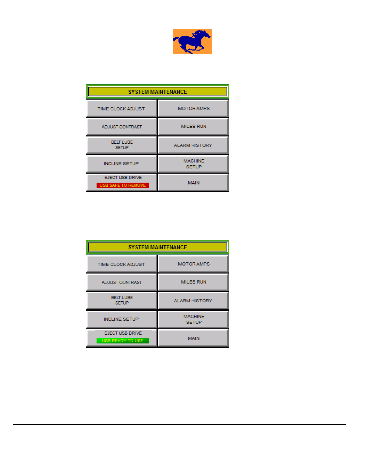
3.6 USB Functions
The trainer is equipped with a USB pen drive that is plugged into the system on the left side of the
operator control panel. The Trainer writes training data to this drive. To remove the USB drive, press the
EJECT USB DRIVE button as depicted below. The indicator to the right of the button should be red and
read USB EJECTED prior to drive removal.
June 5, 2012
Chadwick Engineering Ltd.
TITAN Trainer Equine Treadmill
Model 1677-2
Publication No 1760-260-R1
Chadwick Engineering Ltd. -
TITAN Trainer
Model 1677-2
Installation – Operation – Maintenance
Page 14 of 33
USB Functions Screen
When the USB drive is plugged back into the system, the indicator will be green and read USB READY TO
USE when the system has accepted the drive and is able to write training data to the drive. It may take a
few minutes for the system to accept the drive.
USB Functions Screen
3.7 Motor Amps
The MOTOR AMPS screen displays the belt motor current in amperes.

June 5, 2012
Chadwick Engineering Ltd.
TITAN Trainer Equine Treadmill
Model 1677-2
Publication No 1760-260-R1
Chadwick Engineering Ltd. -
TITAN Trainer
Model 1677-2
Installation – Operation – Maintenance
Page 15 of 33
Motor Amps Screen
3.8 Miles Run
The MILES RUN screen displays the Trainers total miles run.
Miles Run Screen
4.0Trainer Operation

June 5, 2012
Chadwick Engineering Ltd.
TITAN Trainer Equine Treadmill
Model 1677-2
Publication No 1760-260-R1
Chadwick Engineering Ltd. -
TITAN Trainer
Model 1677-2
Installation – Operation – Maintenance
Page 16 of 33
4.1 Emergency Stop
The
TITAN Trainer
is equipped with an emergency stop mushroom head type pushbutton
that can be used to de-energize power to the belt drive motor and hydraulic power unit (for
incline movements) in the case of an emergency situation. This button is located to the left of
the user touch screen.
4.2 Control Power
The control power must be on to use the trainer. The main screen below shows the
“Power Off” message that appears if the control power is off. (Note: Even with power off, the
Programmable Logic Controller (PLC) and the Main Screen remain powered.) In addition to
the message, the Power On/Off green illuminated pushbutton to the left of the touch screen
will be off (not illuminated).
To turn the control power on, first ensure the emergency stop is not depressed. Press the
green “Power On/Off” pushbutton to the left of the touch screen. The green light on the
pushbutton should illuminate. Likewise the control power can be turned off by pressing the
button a second time. Power cannot be re-applied until 30 seconds after the last power off. If
the power has been turned off within the last 30 seconds and the user attempts to turn the
power on the touch screen will display a wait message with the remaining time left before the
power can be turned on.
Main Screen with Power Off & Wait Messages
4.3 Alarms

June 5, 2012
Chadwick Engineering Ltd.
TITAN Trainer Equine Treadmill
Model 1677-2
Publication No 1760-260-R1
Chadwick Engineering Ltd. -
TITAN Trainer
Model 1677-2
Installation – Operation – Maintenance
Page 17 of 33
Should a trainer failure occur, the operator screen displays the fault condition on the bottom of
the touch screen. The following is a list of possible faults and corrective actions.
Alarm Description & Alarm Detail Diagnosis & Corrective Action
1 Stumble Sensor Not Working!
If the sensor does not detect the reflector
located opposite it for more than 120
minutes it is presumed there is a fault.
Check to ensure the surfaces of the reflector and the
photo-sensor are clean and in place.
If the reflector and the sensor are OK then the sensor
may require replacement.
2 Emergency Stop!
The emergency stop button has been
depressed.
Pull the button out and then press the
Stop/Pause/Reset Button to clear the alarm.
3 Incline Failure!
The trainer has failed to raise or lower to the
incline set-point.
Incline transducer may need to be zeroed. See
Section 3.4
4 No Horse Selected – Pick Horse First!
To use either a manual or auto cycle a horse name
must be selected. If the default ---------- is displayed for
the Horse Name, the trainer will not permit operation.
5 Stumble Sensor Tripped!!!
During treadmill operation the stumble
sensor detected the reflector on opposite
side indicating the horse stumbled or fell.
To restart, ensure the horse is ready and in position.
Press the stop button to reset the alarm.
A manual or automatic cycle can now be started.
6 Tail Strap Tripped!!!
During treadmill operation the tail strap
sensor detected the strap was displaced
indicating the horse backed heavily into the
strap.
Reset the tail strap release mechanism and increase
release setting if required by tightening the clamp bolt.
To restart, ensure the horse is ready and in position.
Press the stop button to reset the alarm.
A manual or automatic cycle can now be started.
7 Belt Drive Fault!!!
The electronic belt drive has faulted.
Press the Stop button to reset the drive fault. If
persistent drive faults occur remove the rear platform
cover on the operator side of the treadmill and record
the fault code listed on the drive display. Refer to X4
AC Drive User’s Manual for troubleshooting details.
4.4 Cycle Modes
The
TITAN Trainer
Model 1677-2 can be used in either of two separate cycle modes,
Manual Cycle and Auto Cycle. These cycle modes are further described in the sections
below. To select the cycle mode, on the Main Screen shown below, touch the screen button
for the desired mode.

June 5, 2012
Chadwick Engineering Ltd.
TITAN Trainer Equine Treadmill
Model 1677-2
Publication No 1760-260-R1
Chadwick Engineering Ltd. -
TITAN Trainer
Model 1677-2
Installation – Operation – Maintenance
Page 18 of 33
Main Screen
4.4.1 Manual Cycle
In manual cycle mode the user has the ability to manually adjust the cycle time,
speed, incline and also either select or enter a horse name. The data logging
system is active and recording. To start a manual cycle, the manual cycle screen
must be displayed. Press the start pushbutton on the operator control panel (to
the right of the touch screen). To stop the cycle, press the Stop pushbutton. To
resume a cycle that has been stopped, press the Resume pushbutton. Pressing
the Start button during a cycle will reset the cycle timer and start the cycle from
the beginning.
Manual Cycle Screen

June 5, 2012
Chadwick Engineering Ltd.
TITAN Trainer Equine Treadmill
Model 1677-2
Publication No 1760-260-R1
Chadwick Engineering Ltd. -
TITAN Trainer
Model 1677-2
Installation – Operation – Maintenance
Page 19 of 33
Numeric Keypad
Alphanumeric Keypad
Cycle Time
The cycle time can be adjusted from 0.0 to 60.0 minutes. To adjust the cycle
time, use the up and down increment/decrement arrow keys located to the right of
the Time Set Display or press the Time Set Display. A numeric keypad will pop
up, key in the desired cycle time and press ‘enter’ to accept. The manual cycle
screen also includes a time left display.
Speed
Speed can be adjusted before and during treadmill operation between 0.0 to 15.0
miles per hour. To adjust the speed, use the up and down increment/decrement
arrow keys located to the right of the MPH Set display or press the MPH Set
Display. A numeric keypad will pop up, key in the desired speed and press ‘enter’
to accept. Speed is included in the data collection system.

June 5, 2012
Chadwick Engineering Ltd.
TITAN Trainer Equine Treadmill
Model 1677-2
Publication No 1760-260-R1
Chadwick Engineering Ltd. -
TITAN Trainer
Model 1677-2
Installation – Operation – Maintenance
Page 20 of 33
Incline
Incline can be adjusted before and during treadmill operation between 0 to 8
degrees. To adjust the incline, use the up and down increment/decrement arrow
keys located to the right of the Incline Set Display or press the Incline Set Display.
A numeric keypad will pop up, key in the desired incline and press ‘enter’ to
accept. Incline is included in the data collection system.
Cycle Miles
The miles the horse has run is displayed under cycle miles. Cycle miles is reset
each time the start pushbutton is pressed.
Heart Rate
The horses’ heart rate in beats per minute is monitored and displayed at all times
providing the horse has been fitted with the heart rate transmitter. Heart rate is
included in the data collection system.
Horse Name
A horse name is selected. The horses name is tied to the data collected during a
treadmill cycle. Previously stored horse names can be selected by pressing the
Select Horse display. Alternately a new horse name can be entered manually by
pressing the Horse Name Display. An alpha numeric key pad will pop up. Once
the name has been keyed in, press the enter (‘ENT’) button to accept the entry.
This name will not be stored in memory. If a horse name has not been stored,
press the Select Horse Display then the Setup Horse Name Display. Select the
location where the new horse name will be stored and enter the name.
Manual Cycle Start
To start the manual cycle, press the Start pushbutton to the right of the touch
screen.
Manual Cycle Stop/Pause/Alarm Reset
To stop or pause the manual cycle, press the Stop pushbutton to the right of the
touch screen.
Manual Cycle Resume
If the manual cycle was stopped prior to finishing, it can be resumed by pressing
the Resume pushbutton to the right of the touch screen providing the user has not
left the Manual Cycle Screen.
Manual Cycle Large Display Screen
At any point in time, if the user would prefer to monitor the cycle with larger
graphics, touch the middle of the Manual Cycle Screen and a Large Display
Screen will appear as depicted below. To return to the normal Manual Cycle
screen touch anywhere on the Large Display screen.
This manual suits for next models
1
Table of contents
Popular Treadmill manuals by other brands


NordicTrack
NordicTrack Viewpoint 3500 Treadmill manual
ICON Health & Fitness
ICON Health & Fitness NTL19124.7 user manual

Bodyworx
Bodyworx J1530CA owner's manual

NordicTrack
NordicTrack T 14.0 Treadmill Uživatelská příručka

AbodeFit
AbodeFit WalkSlim WalkPad 630 user manual

Epic
Epic Epic VIEW 550 ECTL09706.1 user manual


