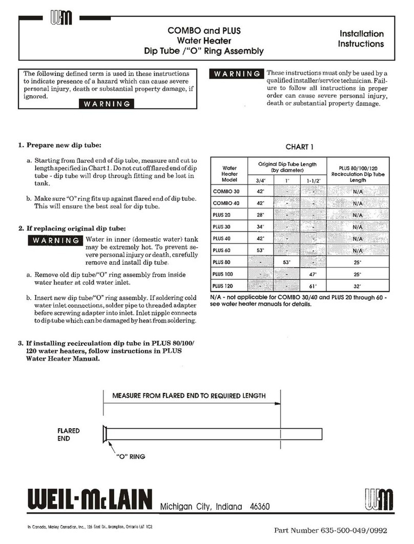
installation
Remove the flue bend from the top of the heat exchanger by
releasing the fixing clip and removing the two screws.
N.B.
: If the optional top fixing bracket is to be used this
should now be attached to the top of the rear casewith the
screwsalready fitted to the case(fig. 3).
Using the heater as a template, locate the spigot of the ap-
pliance in the wall liner, check that the appliance is vertical
and mark the four or five fixing holes. Drill and plug the
wall and fasten the top studs in position. These studs can be
screwedinto the wall by locking two nuts together on the pa-
rallel thread and using a spanner.
Attach the self adhesive foam gasketto the flat surface of the
heater around the air inlet spigot of the rear case. Remove
the protective paper while sticking down the gasket. Lift the
heater into position on the wall, locating on the studs and
the wall liner. Secure the heater to the wall using the nuts
and screwsprovided. The hooks fit under the nuts of the top
fixing studs(fig. 4).
Transfer the terminal fixing chains from the wall linq to
these hoods. The terminal chains should not be left fixed to
the wall liner hooks.
Slide the flue duct through the rectangular hole in the rear
case and engageinto the central spigot of the terminal so
that it touches the two end stops. Relit the flue bend sothat
the flue duct engagesby at least 25 mm (1 in), it may be ne-
cessaryto cut the flue duct to the correct length, and ensure
that the flue bend is seatedcorrectly on the heat exchanger
with the gasketin place. Replace the two screwsand clip se-
curing the flue bend.
Do not relit the front cover until the appliance has been
commissioned.
GAS CONNECTION
Remove the plastic cover from the gasinlet which is the cen-
tre connection on the bottom of the heater.
Fit the gasservice tap provided using the fine filter washer to
seal the connection. Fit the 15 mm dia. copper tail nut and
washer provided to the inlet of the gas service tap and
connect this to the gassupply.
The size of the gassupply pipe from the meter to the heater
only should be asfollows.
Distance from Meter
outlet to heater
O-3
m (O-10It)
3-20
m (lo-65 ft)
20 m and above
Gas Supply
15mm
22
mm
contact British Gas
These sizesare for the heater only and do not take account
of any other gas appliances that may be connected to the
samegasservice pipework.
WATER CONNECTIONS
Remove the plastic covers protecting the water inlet and ou-
tlet connections.
Fit the water service tap provided to the right hand connec-
tion at the bottom of heater using the coarsefilter washer to
sealthe connection.
Fit the 15 m dia. copper tails and washers provided to the
inlet of the water service tap and to the outlet of the heater
(left hand connection).
The water service tap supplied with the heater incorporates
a drain plug.
APPLICATIONS OF THE CORVEC BRITONY II T
The heater is designed to serve a variety of hot water draw-
off points including washing machines and showers. The
heater can be connected to all the hot water draw-off points
in the installation. If more than one.outlet is open simulta-
neously the total flow of water cannot exceedthat quoted in
the Technical data.
The heater is compatible with most current automatic was-
hing machines, but care should be taken to ensure that the
machine is capable of accepting water at the design flow rate
of the heater. Hot and cold fill machines normally require a
hot water temperature of 60” C (140” F), the heater produ-
cing approximately 6.5 l/m (1.44 g.p.m.) at this temperatu-
re. The advice of the washing machine manufacturers
should be sought, but generally it is only necessaryto remo-
ve the water flow restrictor (if fitted) in the hot water inlet
connection of the machine to obtain a satisfactory heater
operation.
ALTERNATIVE
,,,,,,,,, ,,,,,,,, *, ,,,, * ,,,,,,,,,,,m de/j ,,,,,,,, A,,, ,,,,,,, :,
POSITION
5


