Chaffoteaux & Maury Duo 200 Instruction Manual

Supplied By www.heating spares.co Tel. 0161 620 6677
Installation and Maintenance
Instruction Manual
Including User Instructions
CaNI
CHAFFOTEAUX8Md”RY

Supplied By www.heating spares.co Tel. 0161 620 6677
Chaffoteaux & Maury Ltd., as a leading manufacturer of
domestic and commercial water heating appliances, as
well as domestic unvented direct and indirect storage
cylinders, is committed to providing high quality products
and a first class after sales service. If it is necessary to
contact an engineer, then telephone your local
Chaffoteaux Service Centre.
LOCAL CHAFFOTEAUX SERVICE CENTRE
Tel: 0807 243 0224
Advice on installation or servicing can also be obtained
by contacting the Chaffoteaux Customer Services
Department.
CUSTOMER SERVICES DEPARTMENT
Tel : 01952 222288 Fax. 01952 22402
The manufacturer’s guarantee against faulty construction
or materials for the cylinder is 5 years and for the electrical
components, thermal controls and safety valves is for
12 months, from the date of purchase.
The guarantee will be invalidated if the factory fitted
temperature and pressure relief valve is tampered with
or removed. The Manufacturer or Distributors cannot
be held responsible for any damage howsoever caused
and which is a consequence of the removal or tampering.
The guarantee may also be invalidated if the appliance
is not installed by a competent person in accordance
with the recommendations made herein, current
standards, regulations or in a manner not approved by
the manufacturer, modified in any way, subjected to frost,
misuse or neglect and that factory fitted parts have had
unauthorised repairs or replacements carried out.
Evidence of purchase and the date of supply must be
made available at the time of any claim.
To assist us in providing you with an efficient after
sales service, please return the guarantee
registration card enclosed with the cylinder without
delay.
Installation must be carried out by a suitably qualified
installer and in accordance with current regulations
and codes of practice.
Only the safety valves supplied with the cylinder
should be used.
The cylinder must not be used without the safety
valves and expansion vessels.
The cylinder must not be used with a boiler without
thermostatic control.
The cylinder and ancillary controls must be adequately
maintained.
l
The installation must have a sufficient and constant
supply of mains fed cold water.
l
No valve should be fitted between the expansion relief
valve and the storage cylinder.
l
Only Chaffoteaux and Maury approved replacement
parts should be used.
l
The discharge pipe must be terminated where it is
visible and will not cause danger to people in the
vicinity of the discharge.
Note: The discharge could consist of scalding water and
steam.
1 m
C&M

Supplied By www.heating spares.co Tel. 0161 620 6677
page
Customer Care and Guarantee.. ................... .I
Safety Notice .................................................. 1
Contents ........................................................ .2
Table of Figures.. ........................................... .2
Introduction ................................................... .3
Specifications ................................................ .3
Dimensions ................................................... .4
Location of Components ............................... .5
The Cylinder.. ..................................................... .5
Installation ..................................................... .7
Planning ..............................................................
7
Installation ...........................................................
7
Fitting Safety Components ................................. .7
Discharge Pipes ................................................. .7
iwe
Wiring ............................................................ .8
Direct System ...................................................... 8
Indirect system .................................................... 9
Britony System Plus Boiler .................................. 9
Britony System Boiler ......................................... 11
Commissioning.. ........................................... 12
Filling the Cylinder.. ........................................... 12
Check the operation of the safety valves .......... 12
Direct Heating Units .......................................... 12
Indirect Heating ................................................. 12
Post Commissioning .................................... 12
Handing Over to the Householder.. ................... 12
Maintenance ................................................. 13
Routine Maintenance ........................................ 13
Fault Finding Charts ..................................... 14
Spare Parts List.. .......................................... 17
Spare Parts Short List .................................. 17
User’s Instructions.. ...................................... 18
Fig. 1
Fig. 2
Fig. 3
Fig. 4
Fig. 5
Fig. 6
Fig. 7
Fig. 8
Fig. 9
Fig. 10
paw
Dimensions.. ............................................ 4
Combination safety control valves ........... 5
Cylinder connected to System
Plus Boiler ............................................... 5
Cylinder connected to System Boiler.. ..... 6
Discharge pipe arrangement ................... 7
Discharge pipe sizing .............................. 7
Wiring for electrical element .................... 8
Thermostat connections .......................... 9
Thermostat re-set button ......................... 9
Electrical box detail on boiler.. ................. 9
Fig. 11
Fig. 12
Fig. 13
Fig. 14
Fig. 15
Fig. 16
Fig. 17
paw
Hot water on constant and central
heating timed 10
Hot water and heating timed 10
Britony System boiler using
2 x two port valves 11
Deteriorating flow from taps 14
Cold water from taps 14
Discharge from expansion relief valve.. 15
Discharge from temperature and
pressure relief valve 16
2
Supplied By www.heating spares.co Tel. 0161 620 6677
The Chaffoteaux & Maury DUO 120, 150 and 200 are
designed for use as unvented storage cylinders to be
heated indirectly by a sealed system boiler or directly
by the ceramic core electrical element included with
them. The cylinders are enamelled steel with a high
power coil. They are contained within a white case
insulated with CFC free polyurethane foam. There is a
magnesium anode to protect the cylinders against
corrosion.
The unvented storage cylinders will provide the
advantages of mains pressure and higher flow rates to
taps and showers.
Supplied directly from the main water supply they do
not need a separate feed cistern or vent pipe in the loft
space. They can benefit from the high efficiency and
fast recovery provided by modern low water content
sealed system boilers and particularly when used in
conjunction with Chaffoteaux & Maury BRITONY
SYSTEM, SYSTEM PLUS, or COMBI BOILERS. A
better flow rate at main pressure can usually be achieved
when compared with vented or instantaneous systems.
The cylinders have been tested and approved by the
WRc as meeting with the requirements of EN 60335
2.21. EN 60529.
The cylinders should be stored and installed in an upright
position and be protected from extremes of temperature
and humidity at all times. They must never be lifted or
carried by the flow and return pipes or connections.
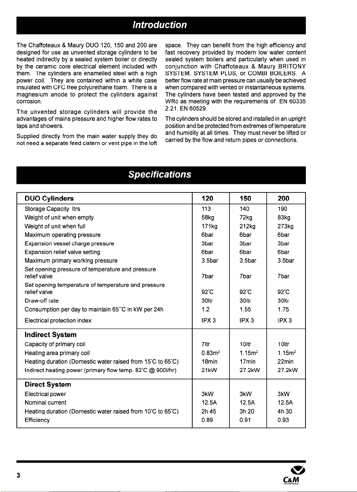
DUO Cylinders
Storage Capacity ltrs
Weight of unit when empty
Weight of unit when full
Maximum operating pressure
Expansion vessel charge pressure
Expansion relief valve setting
Maximum primary working pressure
Set opening pressure of temperature and pressure
relief valve
Set opening temperature of temperature and pressure
relief valve
Draw-off rate
Consumption per day to maintain 65°C in kW per 24h
Electrical protection index
Indirect System
Capacity of primary coil
Heating area primary coil
Heating duration (Domestic water raised from 15°C to 65°C)
Indirect heating power (primary flow temp. 82°C @ 900Vhr)
Direct System
Electrical power
Nominal current
Heating duration (Domestic water raised from 10°C to 65°C)
Efficiency
120 150
113 140
58kg 72kg
171kg 212kg
6bar 6bar
3bar 3bar
6bar 6bar
3.5bar 3.5bar
7bar 7bar
92°C 92°C
301tr 301tr
1.2 1.55
IPX3 IPX3
71tr 1Oltr
0.83m2 1.15m2
18min 17min
21kW 27.2kW
3kW 3kW
12.5A 12.5A
2h 45 3h 20
0.89 0.91
200
190
83kg
273kg
6bar
3bar
6bar
3.5bar
7bar
92°C
301tr
1.75
IPX3
1Oltr
1.15m2
22min
27.2kW
3kW
12.5A
4h 30
0.93
Supplied By www.heating spares.co Tel. 0161 620 6677
Minimumclearance500mm
-
----.
t
280
J
DomestichotwateroutletM3/4” G
v
f
nl Coldwater inletM3/4” G
ll4
c
1
+0550-i , 230 ,
FlowfromheatingboilerM1” G
1
\
DrainpointM3/4” G
-y--I---yq-q--- .
Minimumclearance
600mm
Fig. 1 - Dimensions
reandpressure
/I=‘2/J”G
A B C D
120 I 960mm 935mm 300mm 350mm
150 I 1150mm 1125mm 300mm 500mm
200 I 1435mm 1401mm 300mm 500mm
4
Supplied By www.heating spares.co Tel. 0161 620 6677
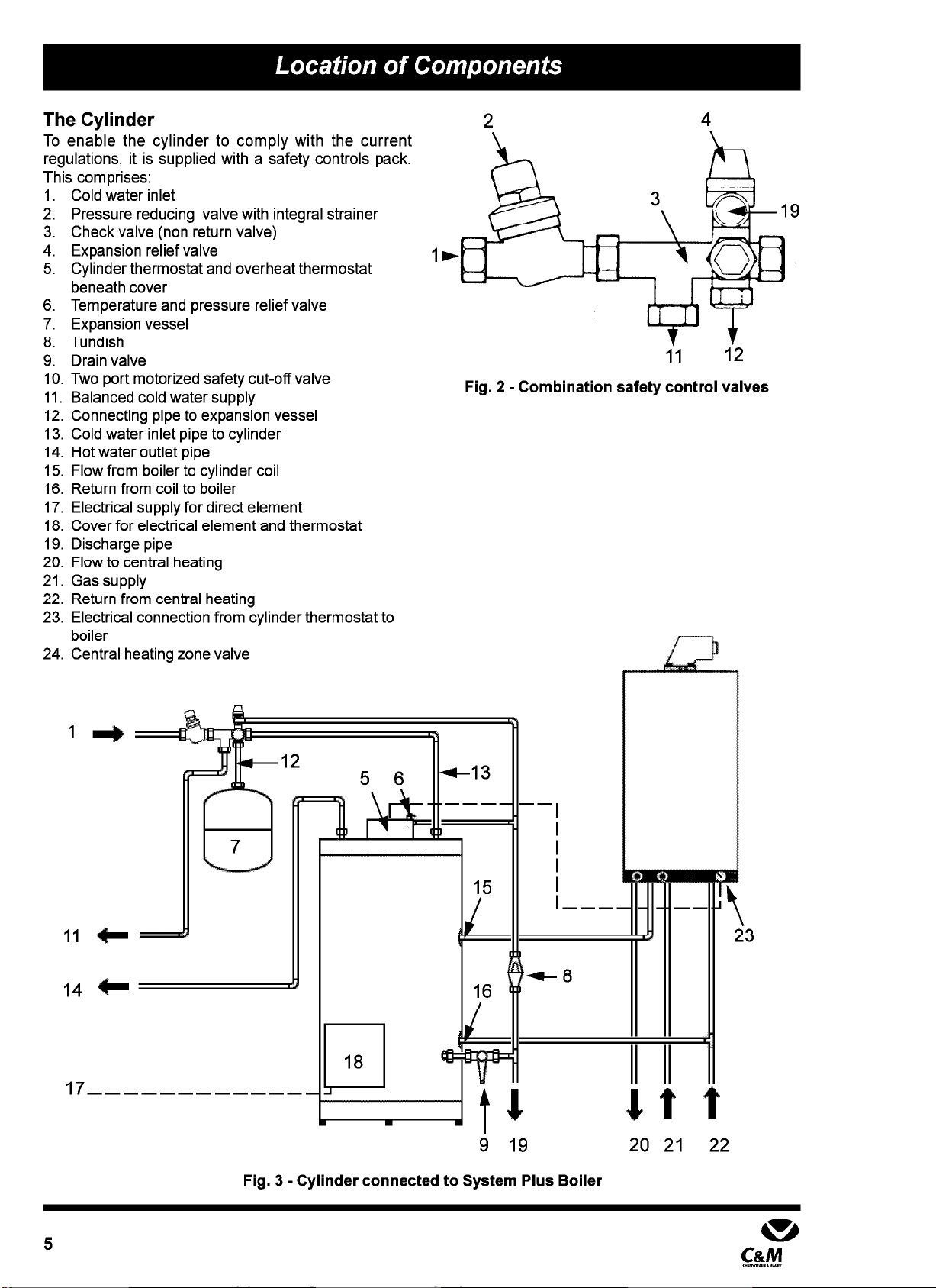
The Cylinder
To enable the cylinder to comply with the current
regulations, it is supplied with a safety controls pack.
This comprises:
1. Cold water inlet
2. Pressure reducing valve with integral strainer
3. Check valve (non return valve)
4. Expansion relief valve
5. Cylinder thermostat and overheat thermostat
beneath cover
6. Temperature and pressure relief valve
7. Expansion vessel
8. Tundish
9. Drain valve
10. Two port motorized safety cut-off valve
11. Balanced cold water supply
12. Connecting pipe to expansion vessel
13. Cold water inlet pipe to cylinder
14. Hot water outlet pipe
15. Flow from boiler to cylinder coil
16. Return from coil to boiler
17. Electrical supply for direct element
18. Cover for electrical element and thermostat
19. Discharge pipe
20. Flow to central heating
21. Gas supply
22. Return from central heating
23. Electrical connection from cylinder thermostat to
boiler
24. Central heating zone valve
2 4
Fig. 2 - Combination safety control valves
Fig. 3 - Cylinder connected to System Plus Boiler
23
5
m
C&M
c.y~.“x.“y”

Supplied By www.heating spares.co Tel. 0161 620 6677
Fig. 4 - Cylinder connected to System Boiler
Please note: the motorised two port safety cut off
valve is only necessary if the cylinders are linked to a
boiler other than the Britony System Plus Boiler.
The Electrical Element
The cylinder contains an alternative source of power.
It is fitted with a 230~ 3 kW ceramic core element with
a factory set thermostat and a manually re-settable
thermal cut-out.
6
Supplied By www.heating spares.co Tel. 0161 620 6677
Planning
The efficient operation of this appliance depends upon a
well-designed system and correct connection to the
boiler. Please familiarise yourself with these installation
instructions as well as the relevant British Standards and
Statutory Regulations. For example, please consult
current versions of the Building Regulations, The Building
Standards for Scotland, the IEE Regulations, the Model
Water Bylaws and the Health and Safety Document No.
635 (The Electricity at Work Regulations 1989) Approved
Document G3. The domestic hot water pipework must
be in accordance with BS 6700. All capillary joints must
be made using lead free solder.
Check that the kit of components is complete.
l
The cylinder must be installed vertically.
l
All pipe runs should be kept as short as possible for
economy.
l
Allow a minimum of 600 mm frontal clearance to allow
the removal of the electrical element and access to
the thermostat.
l
Allow 500 mm access to the top of the appliance to
allow the removal of the sacrificial anode.
l
Provision must be made for the positioning of the
safety valves, expansion vessel and discharge pipes.
l
Ensure that the floor is level and capable of supporting
the weight of the cylinder when full (see page 3).
l
Check that there is sufficient mains pressure and flow
to cater for the combined demands of hot and cold
water for the premises.
Installation
To obtain the best performance from the Chaffoteaux &
Maury DUO, the lowest main working pressure (when
demand on the main supply is at its highest and with a
tap running) should not fall below 20 l/min at 1.5 bar.
Fitting Safety Components
The diagram should be used only for guidance for the
positioning of the safety components and controls.
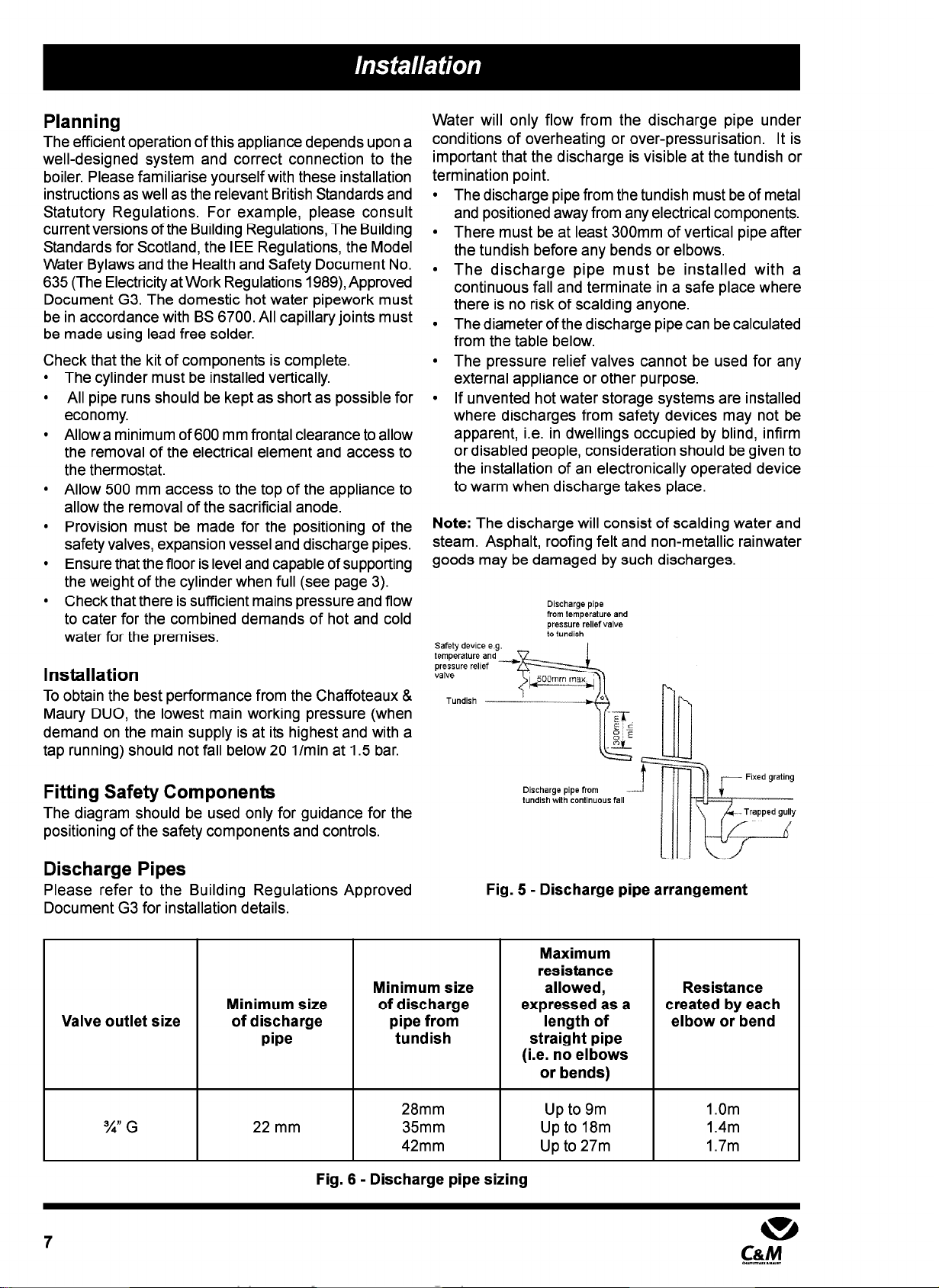
Water will only flow from the discharge pipe under
conditions of overheating or over-pressurisation. It is
important that the discharge is visible at the tundish or
termination point.
l
The discharge pipe from the tundish must be of metal
and positioned away from any electrical components.
l
There must be at least 300mm of vertical pipe after
the tundish before any bends or elbows.
l
The discharge pipe must be installed with a
continuous fall and terminate in a safe place where
there is no risk of scalding anyone.
l
The diameter of the discharge pipe can be calculated
from the table below.
l
The pressure relief valves cannot be used for any
external appliance or other purpose.
l
If unvented hot water storage systems are installed
where discharges from safety devices may not be
apparent, i.e. in dwellings occupied by blind, infirm
or disabled people, consideration should be given to
the installation of an electronically operated device
to warm when discharge takes place.
Note: The discharge will consist of scalding water and
steam. Asphalt, roofing felt and non-metallic rainwater
goods may be damaged by such discharges.
Discharge pipe
from temperature and
pressure relief valve
to tundish
Safety de”lce e g. I
Discharge pipe from
tundish with continuous fall
Discharge Pipes
Please refer to the Building Regulations Approved
Document G3 for installation details. Fig. 5 - Discharge pipe arrangement
Valve outlet size Minimum size
of discharge
pipe
22 mm
Minimum size
of discharge
pipe from
tundish
28mm Up to 9m
35mm Up to 18m
42mm Up to 27m
Maximum
resistance
allowed,
expressed as a
length of
straight pipe
(i.e. no elbows
or bends)
Resistance
created by each
elbow or bend
1.Om
1.4m
1.7m
Fig. 6 - Discharge pipe sizing
7
m
C&M
Supplied By www.heating spares.co Tel. 0161 620 6677
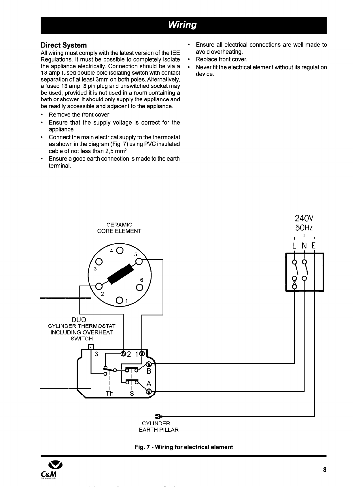
Direct System
l
Ensure all electrical connections are well made to
All wiring must comply with the latest version of the IEE avoid overheating.
Regulations. It must be possible to completely isolate
l
Replace front cover.
the appliance electrically. Connection should be via a
l
Never fit the electrical element without its regulation
13 amp fused double pole isolating switch with contact device.
separation of at least 3mm on both poles. Alternatively,
a fused 13 amp, 3 pin plug and unswitched socket may
be used, provided it is not used in a room containing a
bath or shower. It should only supply the appliance and
be readily accessible and adjacent to the appliance.
l
Remove the front cover
l
Ensure that the supply voltage is correct for the
appliance
l
Connect the main electrical supply to the thermostat
as shown in the diagram (Fig. 7) using PVC insulated
cable of not less than 2,5 mm2
l
Ensure a good earth connection is made to the earth
terminal.
CERAMIC
CORE ELEMENT
240V
50Hz
1
I
CYLlrJbER
EARTH PILLAR
Fig. 7 -Wiring for electrical element
8
Supplied By www.heating spares.co Tel. 0161 620 6677
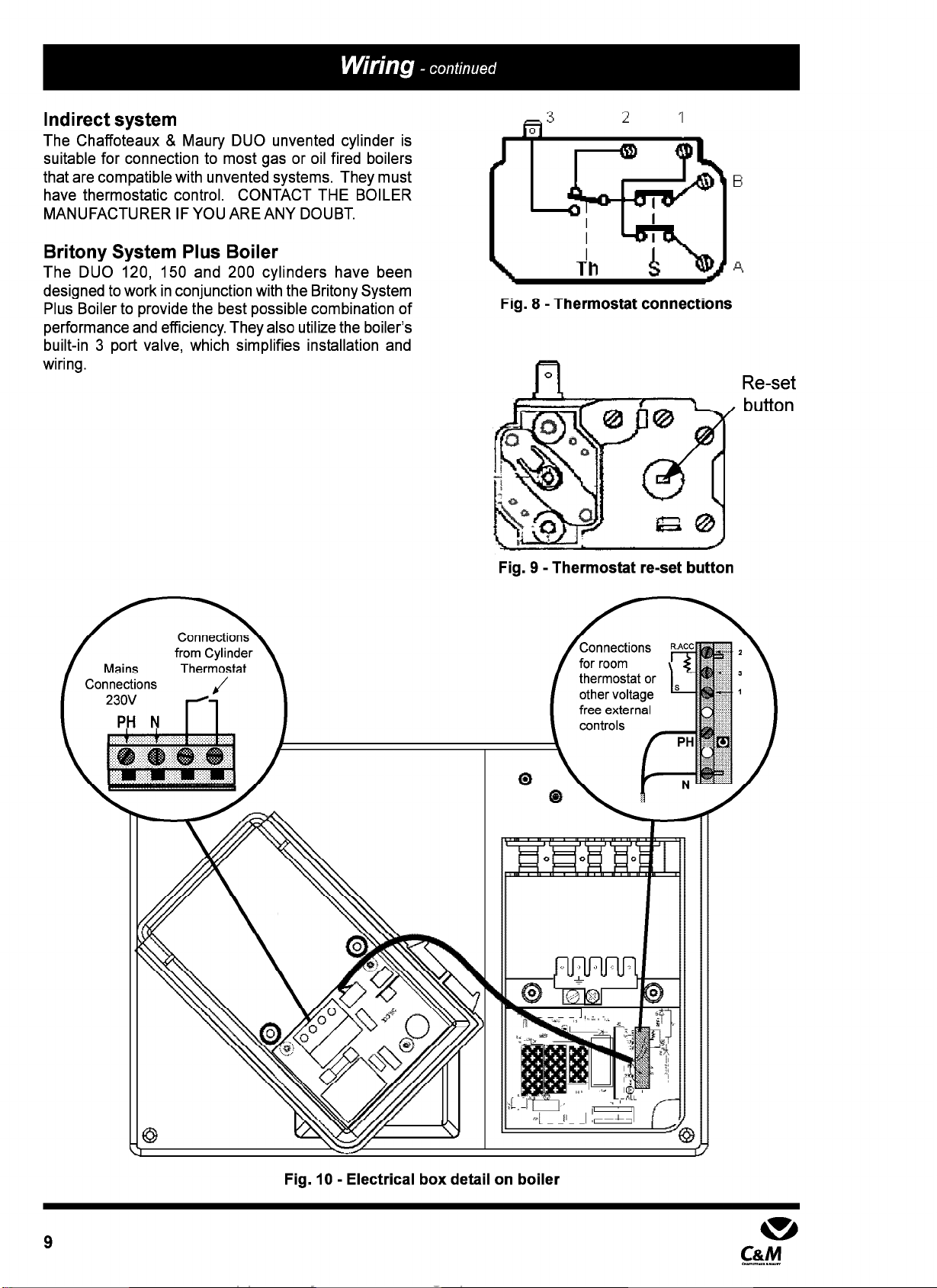
Indirect system
The Chaffoteaux & Maury DUO unvented cylinder is
suitable for connection to most gas or oil fired boilers
that are compatible with unvented systems. They must
have thermostatic control. CONTACT THE BOILER
MANUFACTURER IF YOU ARE ANY DOUBT.
Britony System Plus Boiler
The DUO 120, 150 and 200 cylinders have been
designed to work in conjunction with the Britony System
Plus Boiler to provide the best possible combination of
performance and efficiency. They also utilize the boiler’s
built-in 3 port valve, which simplifies installation and
wiring.
/
co
from Cylinder
Mains Thermostat
“-nnections J
Fig. 8 -Thermostat connections
Fig. 9 - Thermostat re-set button
Reset
button
Fig. 10 - Electrical box detail on boiler
9 m
C&M

Supplied By www.heating spares.co Tel. 0161 620 6677
Option 1
Using a hot water priority system with the hot water on
constantly and the heating timed. Asimple time clock
can be use such as the Randall 103.
Timeclock
(for example Randall 103)
er
q
Interface PC
Fig. 11 - Hot water on constant and central heating timed
Option 2
Using hot water priority with a timed facility for both hot
water and central heating. A twin channel clock such
as the Horstman Channelplus Model H27 must be used.
Two Channel Programmer
For example
Horstman Channelplus
IhJl
resistor
Model H27
Thermostat
Fig. 12 - Hot water and heating timed
10

Supplied By www.heating spares.co Tel. 0161 620 6677
Britony System Boiler
When the Britony System boiler (or a boiler from another
manufacturer) a two port safety cut off valve must be
used. This is supplied with the cylinder. It can be used
together with another two port valve, to provide timed
control over the heating and hot water circuits.
Fused
Spur
Fig. 13 - Britony System boiler using 2 x two port valves

Supplied By www.heating spares.co Tel. 0161 620 6677
Filling the Cylinder
l
Do not turn on electrical power to the immersion
heater without water in the cylinder.
l
Ensure that all fittings, valves and the immersion
heater are correctly installed and are watertight.
l
Flush all debris from the supply pipes before
connecting to the cylinder.
l
Open the furthest hot water tap from the cylinder.
l
Open the main valve and allow the cylinder to fill
steadily. Allow water to flow from the tap for a few
minutes to ensure any installation debris is flushed
through the system.
l
Open all other taps in turn to purge any remaining
air from the system.
l
Check all connections for leaks.
Check the operation of the safety valves
l
Manually open the temperature and pressure relief
valve (6 Fig. 3) for a few seconds.
l
Check that the water flows away through the tundish
and discharge pipework and does not overflow.
l
Ensure that the flow of water has stopped and that
the valve has reseated itself.
l
Repeat the above check for the expansion relief
valve.
Direct Heating Units
l
Carry out an electrical test for earth continuity, correct
polarity, short circuit and fuse continuity.
l
Turn on the electrical supply and allow the water to
heat up.
l
Check the correct operation of the cylinder
thermostat.
l
Check that water is not discharged from either the
expansion relief or the temperature and pressure
relief valves.
Indirect Heating
l
Refer to the boiler commissioning instructions.
l
Ensure that the cylinder heating coils are filled and
purged of air.
l
Light boiler and allow the cylinder to heat up.
l
Check the correct operation of the cylinder
thermostat.
l
Check that water is not discharged from either the
expansion relief or the temperature and pressure.
Handing Over to the Householder
l
Ensure system pressure has been set correctly
l
Set boiler and cylinder thermostat and controls
l
Demonstrate the lighting and operation of the boiler
l
Demonstrate how to maintain system pressure
l
Explain to the customer :
1. the operation of the appliance and safety
controls
2. things to look out for such as a continual leak of
water noticed at the tundish
3. Explain the necessity for annual maintenance
by a competent person
4. what to do in an emergency
l
Leave instruction manual with the customer
l
Fill out guarantee card and return to Chaffoteaux &
Maury Ltd.
12
Supplied By www.heating spares.co Tel. 0161 620 6677
In order to ensure that the cylinder continues to operate
efficiently and safely, it is essential that it is serviced
and inspected annually. This may be timed to coincide
with the annual boiler maintenance.
l
Servicing and repairs should only be carried out by a
competent engineer.
l
Any part replaced should be genuine Chaffoteaux &
Maury spare parts.
Routine Maintenance
Before continuing with any maintenance, ensure
that the boiler has been turned off and that the
electrical supply has been isolated.
1. Electrical Element
Check the operation of the electrical element thermostat
by turning off the boiler and running off some hot water.
Allow the electrical element to reheat the water to its set
temperature. Check that no water is discharged from
the expansion or temperature relief valves. As the
electrical element is not indirect contact with the water,
it is not necessary to check it for scaling.
2. Sacrificial Anode
Drain the cylinder by turning off the main water inlet valve
and opening the lowest hot water tap to depressurise
the system. Open the drain valve (9 Fig. 3) and drain
approximately 5 litres.
The anode is located at the top of the cylinder. Remove
the cover. Disconnect the outlet pipe to from the T+P
valve. Unscrew 6 screws and lift the top plate clear.
When new the diameter of the anode is 26mm. If at
any point along its length the diameter has reduced to
half or less than half its original diameter, then it should
be replaced by unscrewing from the top plate.
Replace components in the reverse order using a new
gasket for the top plate.
3. Strainer
While the cylinder is partially drained the strainer can
be removed and cleaned.
4. Expansion Vessel
While there is no pressure in the system the pressure
in the expansion vessel can be checked against the
pressure on the data badge.
Refill and Re-pressurise the system as set out in the
commissioning instructions.
5. Safety Valves
Manually operate the temperature, pressure and
expansion relief valves. Check that water runs freely
through the tundish and at the discharge point without
overflowing. Check that the flow of water stops and that
the valves reseat satisfactorily.
13
m
C&M
c.y~.“x.“y”
Supplied By www.heating spares.co Tel. 0161 620 6677
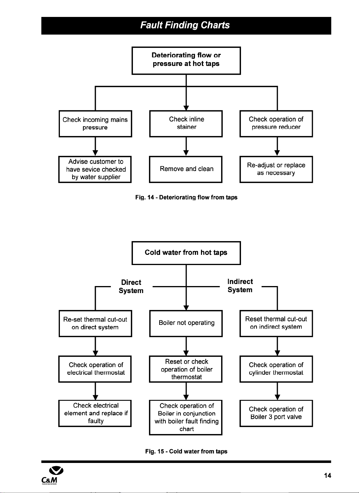
Deteriorating flow or
pressure at hot taps
I 1 I v 1 I
I
Check incoming mains
I I
Check inline
pressure stainer Check operation of
pressure reducer
Advise customer to
have sevice checked
by water suoolier
Re-adjust or replace
as necessary
Remove and clean
Fig. 14 - Deteriorating flow from taps
I
Cold water from hot taps I
+
Boiler not operating
Reset or check
operation of boiler
thermostat
1
Check operation of
Boiler in conjunction
with boiler fault finding
chart
Fig. 15 - Cold water from taps
Indirect
System
1
Direct
r
System
I
Reset thermal cut-out
on indirect system
Re-set thermal cut-out
on direct system
Check operation of
electrical thermostat Check operation of
cylinder thermostat
I
Check operation of
Boiler 3 port valve
Check electrical
element and replace if
faulty
14

Supplied By www.heating spares.co Tel. 0161 620 6677
Discharge from Expansion Relief Valve
-I
Reset pressure
Manually reset/reseat
valve.
Is discharge still
4
ocurring?
I
Yes
4
conditions? I
Adjust or replace
faulty component + No Are the boiler and
cylinder thermostats
operating correctly?
Yes
I Service or exchange
expansion relief valve
Is the pressure
downstream of the
pressure regulator
correct?
Service or replace
pressure regulator
Please Note:
Use only genuine Chaffoteaux replacement parts
Fig. 16 - Discharge from expansion relief valve
m
C&M
c.y~.“x.“y”
Supplied By www.heating spares.co Tel. 0161 620 6677
D
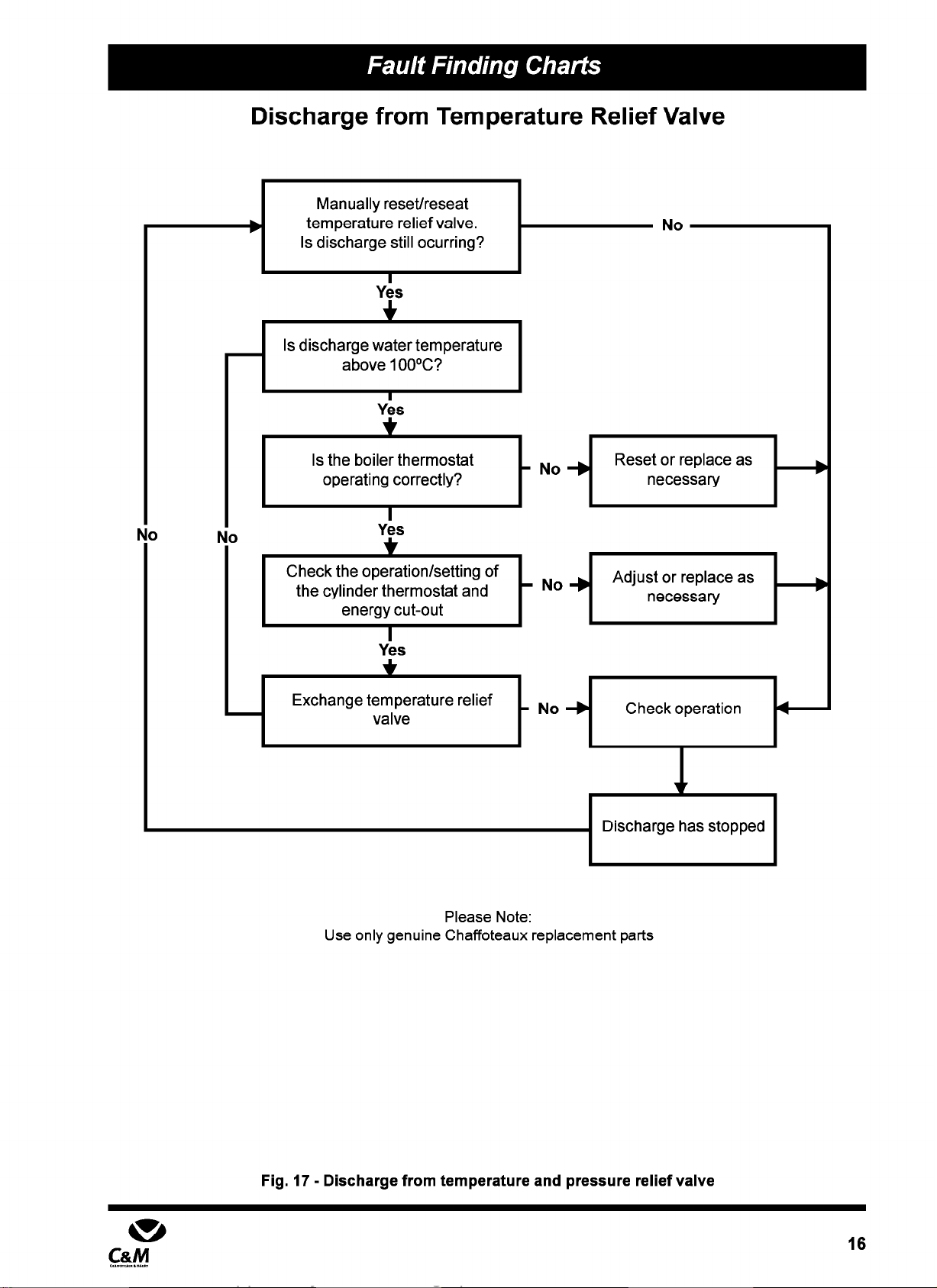
Discharge from Temperature Relief Valve
Manually reset/reseat I
I
Is discharge still ocurring? I
Yes
Is discharge water temperature
above 1OOOC?
Yes
Check the operation/setting of
Yes
+
- No +
Reset or replace as
necessary
Adjust or replace as
necessary t+
]]/ No -) Checkoperation e
I I
Discharge has stopped
Please Note:
Use only genuine Chaffoteaux replacement parts
Fig. 17 - Discharge from temperature and pressure relief valve

Supplied By www.heating spares.co Tel. 0161 620 6677
9
10 -
11 -
12
6
17
m
C&M
Supplied By www.heating spares.co Tel. 0161 620 6677
There are no user adjustable controls on the DUO. The
immersion heater thermostat will have been set on
installation. A suitably qualified engineer, installer or
electrician must carry out any adjustments or
maintenance.
If water is seen discharging from the DUO Safety
Valves
l
Turn off the electrical supply to the immersion heater
l
Turn off the boiler
l
Do not turn off the water supply
l
Contact the installer or other suitably qualified
engineer.
In order to ensure that the cylinder continues to operate
efficiently and safely, it is essential that it is serviced
and inspected annually. This may be timed to coincide
with the annual boiler maintenance.
l
Servicing and repairs should be carried out by a
competent engineer.
l
Any part replaced should be genuine Chaffoteaux &
Maury spare part.
If the thermal cut out is activated, it is necessary to reset
and check the operation of both thermostats fitted to
the cylinder (immersion heating and indirect heating
thermostats).
Chaffoteaux & Maury Ltd are continuously improving
their products and therefore reserve the right to change
specifications without prior notice and accept no liability
for any errors or omissions in the information contained
in this document.
18

Supplied By www.heating spares.co Tel. 0161 620 6677
Chaffoteaux et Maury are contunuously improving their products and therefore reserve the right to change specifications without
prior notice and accepts no liability for any errors or omission in the information contained in this document.
0 Chaffoteaux & Maury Limited 1999 +
Chaffoteaux & Maury Limited, Trench Lock, Trench, Telford, Shropshire TFI 4SZ. 3
Telephone: 01952 222727 / Facsimile: 01952 243493 0
Technical Helpline: 01952 222288 /Technical Fax:01952 2609151 In Warranty Service: 0870 2430224
Table of contents
Popular Water System manuals by other brands


US Water Systems
US Water Systems L1-200 manual

Watts Premier
Watts Premier 5 SV DELUXE Installation, operation and maintenance manual

Filtrete
Filtrete 4US-MAXS-S01 Installation and operating instructions

EnerWorks
EnerWorks EWRA2 installation manual

Davey
Davey Dynajet X50 Installation and operating instructions

Zip
Zip HydroTap G5 Touch-Free Wave Quick start installation guide

Watts
Watts BA 009MC Installation and operation manual

SolarArk
SolarArk Solar Hot Water Systems installation manual

Marlo Incorporated
Marlo Incorporated RO-25T operating manual

clage
clage Zip HydroTap G5 CS 100 operating instructions

Everpure
Everpure ExuberaPRO Premium Carafe Water System brochure

Kärcher
Kärcher WPC 600 BW operating instructions