US Water Systems L1-200 User manual

1REVISION 1.0, 1-19-15
US Water Systems 300 GPD
Premium Wall-Mount Light Commercial
RO System

2REVISION 1.0, 1-19-15
TABLE OF CONTENTS
INTRODUCTION...............................................................................................................................3
SAFETY.............................................................................................................................................4
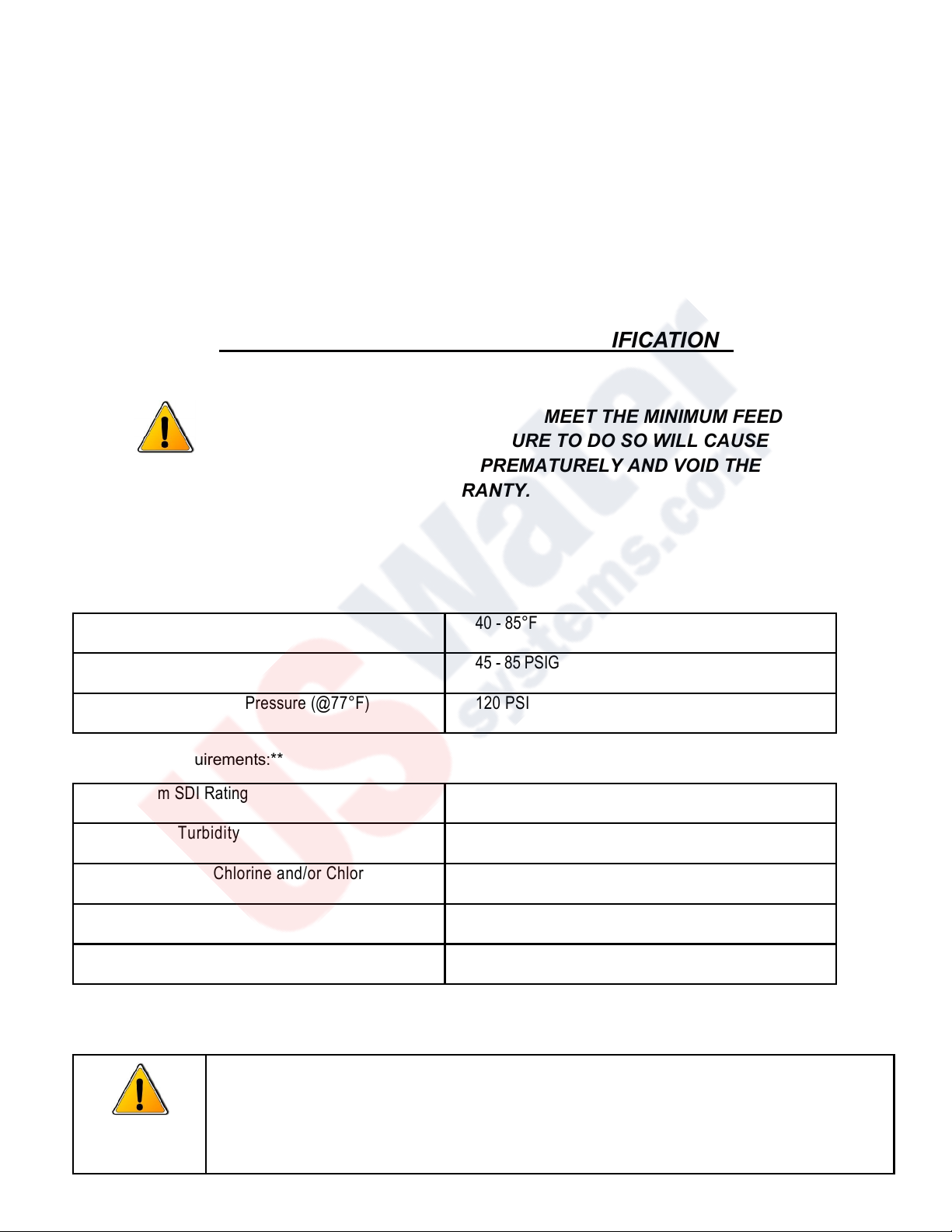
FEED WATER AND OPERATION SPECIFICATIONS ....................................................................5
REJECTION, RECOVERY AND FLOW RATES ..............................................................................6
SYSTEM INSTALLATION AND START-UP PROCEDURES ..........................................................7
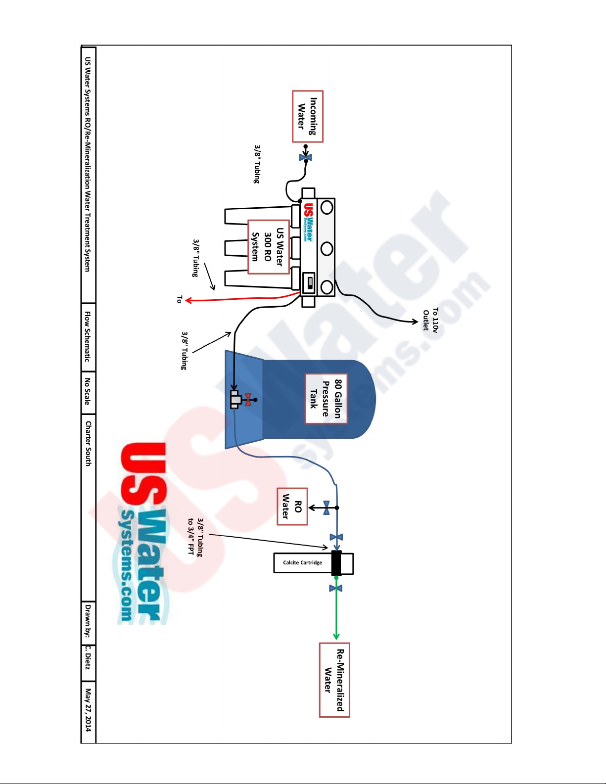
SYSTEM CONFIGURATION DRAWINGS…..…………………………………………………………..9
MEMBRANE ELEMENTS ...............................................................................................................10
SYSTEM IDENTIFICATION............................................................................................................11
MEMBRANE INSTALLATION, REMOVAL AND REPLACEMENT................................................12
OPERATION DO’S AND DON’TS ..................................................................................................15
SPECIFICATIONS...........................................................................................................................16
OPERATION AND MAINTENANCE ...............................................................................................18
PREPARING UNIT FOR STORAGE OR SHIPMENT ....................................................................19
REVERSE OSMOSIS TROUBLESHOOTING................................................................................20
TEMPERATURE CORRECTION FACTORS FOR MEMBRANE...................................................21
SERVICE ASSISTANCE.................................................................................................................21
OPERATION LOG...........................................................................................................................23
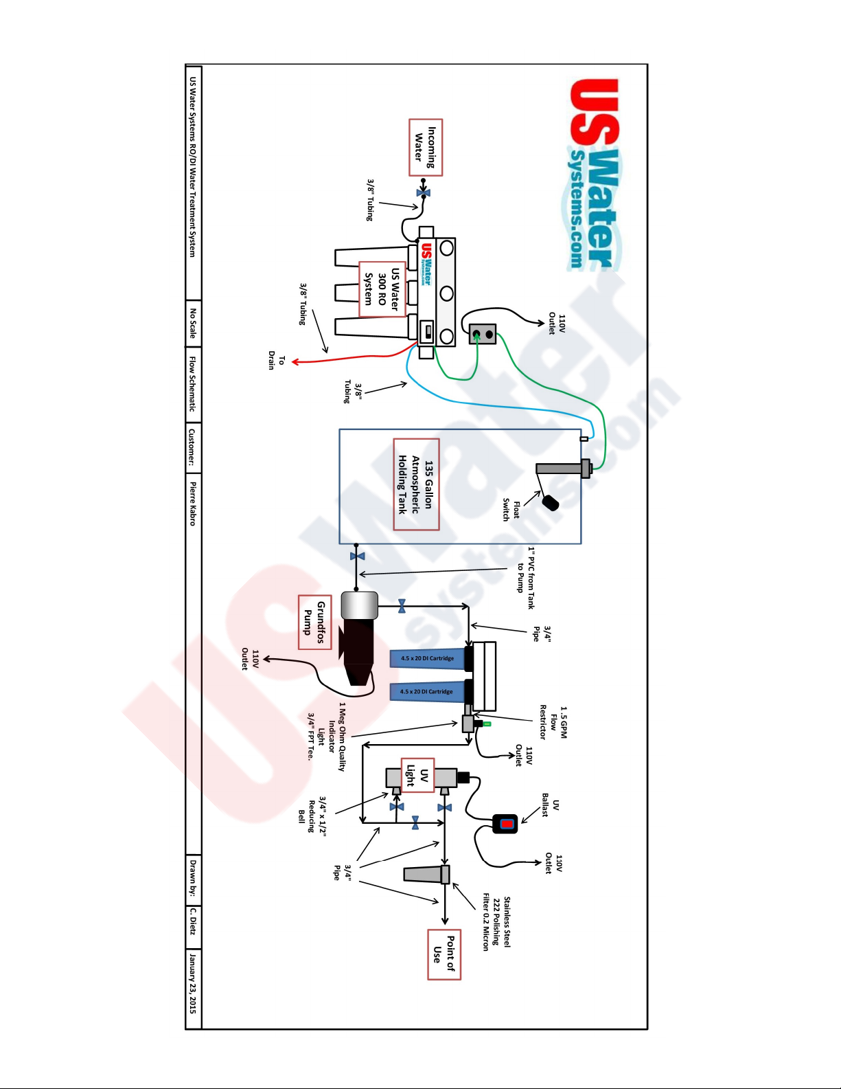
SYSTEM DRAWING .......................................................................................................................24
L1-200 SERIES FLOW DIAGRAM..................................................................................................25
L1 - SERIES ELECTRICAL SCHEMATIC 110V/60HZ...................................................................26
L1 - SERIES ELECTRICAL SCHEMATIC 220V/50HZ...................................................................27
REVERSE OSMOSIS SYSTEM WARRANTY................................................................................28

3REVISION 1.0, 1-19-15
INTRODUCTION
The US Water Systems 300 GPD Light Commercial RO System is a durable piece of
equipment which, with proper care, will last for many years. This User’s Manual outlines
installation, operation, maintenance and troubleshooting details vital to the sustained per-
formance of the system.
If the RO system is altered at the site of operation, or if the feed water conditions
change, please consult US Water Systems for assistance.
NOTE: IN ORDER TO MAINTAIN THE MANUFACTURER’S WARRANTY,
AN OPERATING LOG SHOULD BE MAINTAINED. COPIES MAY NEED
TO BE SENT TO US WATER SYSTEMS FOR REVIEW.
NOTE: PRIOR TO OPERATING OR SERVICING THE REVERSE OSMO-
SIS SYSTEM, THIS USER’S MANUAL MUST BE READ AND FULLY
UNDERSTOOD. KEEP THIS AND OTHER ASSOCIATED INFOR-
MATION FOR FUTURE REFERENCE. THESE DOCUMENTS CAN BE
USED TO TRAIN NEW OPERATORS OR QUALIFIED PERSONNEL
THAT MAY BE NEAR THE SYSTEM.

4REVISION 1.0, 1-19-15
SAFETY
The Safety section of this User’s Manual outlines the various safety headings used
throughout this manual’s text and are enhanced and defined below:
NOTE: INDICATES STATEMENTS THAT PROVIDE FURTHER INFORMATION AND
CLARIFICATION.
CAUTION: INDICATES STATEMENTS THAT ARE USED TO IDENTIFY CON-
DITIONS OR PRACTICES THAT COULD RESULT IN EQUIPMENT OR OTHER
PROPERTY DAMAGE.
WARNING: INDICATES STATEMENTS THAT ARE USED TO IDENTIFY CON-
DITIONS OR PRACTICES THAT COULD RESULT IN INJURY OR LOSS OF
LIFE. FAILURE TO FOLLOW WARNINGS COULD RESULT IN SERIOUS INJU-
RY OR EVEN DEATH.
DO NOT UNDER ANY CIRCUMSTANCE REMOVE ANY CAUTION, WARNING,
OR OTHER DESCRIPTIVE LABELS FROM THE SYSTEM.
PLEASE READ THE ENTIRE MANUAL BEFORE PROCEEDING WITH THE
INSTALLATION AND STARTUP. FAILURE TO FOLLOW THE ATTACHED
INSTRUCTIONS OR OPERATING PARAMETERS MAY LEAD TO THE
PRODUCT’S FAILURE, WHICH CAN CAUSE PROPERTY DAMAGE AND/OR
PERSONAL INJURY.
DO NOT USE WHERE THE WATER IS MICROBIOLOGICALLY UNSAFE OR OF UN-
KNOWN QUALITY WITHOUT ADEQUATE DISINFECTION BEFORE OR AFTER THE
SYSTEM.
PRETREATMENT MUST BE SUFFICIENT TO ELIMINATE CHEMICALS, ORGANICS OR
INORGANICS THAT COULD ATTACK THE MEMBRANE MATERIAL.
ALWAYS TURN OFF THE UNIT, SHUT OFF THE FEED WATER, AND

5REVISION 1.0, 1-19-15
DISCONNECT THE ELECTRICAL POWER BEFORE WORKING ON THE UNIT.
NEVER ALLOW THE PUMP TO RUN DRY.
NEVER ALLOW THE UNIT TO FREEZE OR OPERATE WITH A FEED WATER TEM-
PERATURE ABOVE 100°F.
FEED WATER AND OPERATION SPECIFICATIONS
NOTE: IT IS VERY IMPORTANT TO MEET THE MINIMUM FEED
WATER REQUIREMENTS. FAILURE TO DO SO WILL CAUSE
THE MEMBRANE TO FOUL PREMATURELY AND VOID THE
MANUFACTURER’S WARRANTY.
OPERATING LIMITS
Operating Parameters:*
Feed Water Requirements:**
**If any of the feed water parameters are not within the limits given, consult your local dealer or
distributor for assistance.
Feed Temperature 40 - 85°F
System Inlet Pressure 45 - 85 PSIG
Maximum Operating Pressure (@77°F) 120 PSIG (Nominal)
Maximum SDI Rating < 3
Maximum Turbidity 1 NTU
Maximum Free Chlorine and/or Chloramines 0 PPM
pH (continuous) 3 - 11
pH (cleaning - 30 min.) 2 - 12
NOTE: HIGHER TDS AND/OR LOWER TEMPERATURES WILL RE-
DUCE THE SYSTEM’S PRODUCTION. 2% OF THE SYSTEM OUT-
PUT CAN BE LOST FOR EVERY DEGREE “F” BELOW 77.

6REVISION 1.0, 1-19-15
REJECTION, RECOVERY AND FLOW RATES
US Water Systems 300 GPD Reverse Osmosis Systems are designed to produce perme-
ate water at the capacities indicated by the suffix in the system’s name under the condi-
tions listed above. For example, the US Water Systems 300 GPD Reverse Osmosis Sys-
tem produces 300 gallons per day of permeate water at the listed operating test condi-
tions.
The amount of total dissolved solids (TDS) rejected by the membrane is expressed as a
percentage. For example, a 98.5% rejection rate means that 98.5% of total dissolved solids
do not pass through the membrane. To calculate the % rejection, use the following formu-
la:
% Rejection = [(Feed TDS – Product TDS) / Feed TDS] x 100
Example:
98.5% = [(550-8.25)/550] x 100
NOTE: ALL TDS FIGURES MUST BE EXPRESSED IN THE SAME UNITS, TYPI-
CALLY PARTS PER MILLION (PPM) OR MILLIGRAMS PER LITER (MG/L).
US Water Systems 300 GPD Reverse Osmosis Systems are designed to reject up to
98.5% NaCl, unless computer projections have been provided or stated otherwise.
The amount of permeate water recovered for use is expressed as a percentage. To cal-
culate % recovery, use the following formula:
% Recovery = (Product Water Flow Rate / Feed Water Flow Rate) x 100
Example:
28% = (0.14/0.50) x 100
NOTE: ALL FLOW RATES MUST BE EXPRESSED IN THE SAME UNITS,
TYPICALLY GALLONS PER MINUTE (GPM).

7REVISION 1.0, 1-19-15
SYSTEM INSTALLATION AND START-UP PROCEDURES
1. Inspect the system for any damage that could have occurred during shipment. Although all sys-
tems have been individually inspected, complete a quick inspection of the fittings, tubing and other
components.
2. Please provide a reasonable amount of space for installation and leave 6 inches of space below the
filter housings for easy removal during maintenance endeavors.
NOTE: THE REVERSE OSMOSIS SYSTEM SHOULD BE INSTALLED
INDOORS AND IT IS SUGGESTED THAT IT NOT BE IN DIRECT SUNLIGHT OR
EXTREME COLD.
3. Connect the 3/8” tube fitting to an incoming water source. The minimum feed water pressure
should be at least 30 psi. The system’s minimum operating (membrane) pressure is 80 PSI, but the
optimum operating pressure is 100 psi.
NOTE: DO NOT OPERATE AT A PRESSURE EXCEEDING 125 PSI. The operating
pressure can be increased on the face of the booster pump by turning the hex screw clock-
wise.
4. Connect the concentrate 3/8” tubing (waste) line to drain.
5. Turn on the feed water and plug the booster pump transformer into a power supply of 110 volts 60 Hz.
6. This system has been designed with an auto-flush restrictor. This restrictor automatically flushes the
reverse osmosis system for 30 seconds every time it starts up and once every hour when the system is
producing water.
NOTE: THE TANK PRESSURE SWITCH WILL SHUT THE SYSTEM OFF
AUTOMATICALLY WHEN THE BLADDER TANK IS FULL.

8REVISION 1.0, 1-19-15
7. The sediment filter and carbon must be serviced regularly for optimal performance. The water quali-
ty should be checked every two weeks minimum. The pre-filters should be checked once a month
over the first 3 months of operation to determine the filter change frequency. Typically most appli-
cations will not need to change the filters more than twice annually. However, in some applications
sediment or other contaminants in the feed water may require a more frequent filter change.
8. Dispose of the initial product (clean) water until the TDS level/conductivity of the product water sta-
bilizes at the lowest (cleanest) value. Use any TDS or Conductivity meter to monitor the product wa-
ter quality. A minimum quality of 96% NaCl rejection is recommended (See the rejection rate calcu-
lation).
9. Once the system has been flushed and the TDS level has stabilized, the permeate/product line can
be attached to the storage tank. Additional flushing of the storage tank and distribution system
may be required to reach the TDS level that is produced directly after the RO system at all points of
use.
10. This system has been factory wired and preset with a pressure switch at 20 - 40 psi, which is only to
be used with a pressurized bladder tank. If using an atmospheric storage tank, a float switch will be
required to turn the system on and off. An electric float switch can be used. The main power can
be switched by using a “piggy back” connector type float switch or an outlet can be wired to switch
power on and off utilizing a float switch. US Water uses an outlet configuration float switch for the
300 GPD RO system. Please see the following typical float diagram and complete system layout.
NOTE: ANY CHLORINE EXPOSURE WILL DAMAGE THE MEMBRANE.

9REVISION 1.0, 1-19-15

10 REVISION 1.0, 1-19-15

11 REVISION 1.0, 1-19-15

12 REVISION 1.0, 1-19-15
SYSTEM IDENTIFICATION

13 REVISION 1.0, 1-19-15
MEMBRANE INSTALLATION, REMOVAL AND REPLACEMENT
Installation and replacing membranes in the pressure vessels is an easy process with the proper infor-
mation and tools at hand. Please refer to the following instructions when removing and replacing mem-
brane elements:
WARNING: ALL PRESSURE GAUGES MUST READ ZERO BEFORE PROCEED-
ING. BEFORE ATTEMPTING, DISCONNECT THE POWER FROM THE SYSTEM
AND BLEED ALL WATER PRESSURE FROM THE SYSTEM.
1. Remove the end cap from the right (feed water) side of the membrane housings. This is done by remov-
ing the two half-moon retaining disks using a #5 Allen wrench, the end plug should then freely slide out of
the pressure vessel. The tubing must be disconnected to remove the cap fully.
2. Remove the membrane bag containing the membrane element from the shipping box. The mem-
brane should be contained within a plastic oxygen barrier bag.
NOTE: WEAR GLOVES FOR THE FOLLOWING STEPS TO PROTECT THE MEMBRANE
FROM CONTAMINATION.
3. Cut the bag open as close as possible to the seal at one end of the bag, so the bag may be re-used if nec-
essary.

14 REVISION 1.0, 1-19-15
4. Make sure that all parts are clean and free from dirt. Examine the brine seal, and permeate tube for
nicks or cuts. Replace the cap O-rings or membrane brine seal if damaged.
5. Flow directions should be observed for installation of the membrane element into the pressure vessels.
REPLACING THE MEMBRANE ELEMENT:
WARNING: THE BRINE SEAL MUST BE IN THE SAME POSITION AS IT WAS FOR FACTORY PRE-
INSTALLED MEMBRANE ELEMENT. THE BRINE SEAL IS A RUBBER SEAL THAT PRO-
TRUDES ON ONE SIDE OF THE MEMBRANE AND IS ALWAYS ON THE FEED SIDE OF
THE MEMBRANE ELEMENT. FOR L1 SERIES RO SYSTEMS THE BRINE SEAL SHOULD
BE ON THE RIGHT SIDE OF THE MEMBRANE HOUSING.
BRINE
SEAL

15 REVISION 1.0, 1-19-15
1. Remove membrane element from the right (feed water) side of the membrane housing. Long nose pliers
may be necessary to pull the old membrane element out of the membrane element housing.
2. Lubricate the membrane brine seal and cap o-rings with a non-petroleum based lubricant.
3. Install membrane through the right side (feed water) of the membrane housing with brine seal located on
the feed water side.
4. Push the membrane in the housing from right to left (brine seal on the right). Once the membrane is in
place make sure it is fully seated in the housing.
5. Lubricate the O-rings on the cap and re-install the cap (6, Figure 1.A) on the right side by gently twisting
it, while pushing it onto the housing. Ensure that you do not pinch or fatigue any O-rings while re- in-
stalling the end plug. Push the end plug on until the outer diameter of the plug is flush with the outer di-
ameter of the pressure vessel. Lubricating the inner and outer O-rings will make the cap installation easi-
er.
6. Insert the two half-moon retaining disks until they are fully seated. Subsequently fasten
using a #5 Allen wrench.
7. Reconnect any fittings that may have been disconnected when the membrane pressure vessels were dis-
assembled.
8. To Start-Up the system, please refer to the Initial Start -Up section of this manual.
CAUTION: WET MEMBRANES ARE SHIPPED IN A PRESERVATIVE SOLUTION. THE
MEMBRANES MUST BE FLUSHED FOR AT LEAST 30 MINUTES TO RE-
MOVE THE PRESERVATIVE FROM THE MEMBRANE. DISCARD ALL OF THE
PERMEATE, WHICH IS PRODUCED DURING THE FLUSH PERIOD.

16 REVISION 1.0, 1-19-15
OPERATION DO’S AND DON’TS
DO:
Change the cartridge filters regularly
Monitor the system and keep a daily log
Run the system as much as possible on a continuous basis
Always feed the pump with filtered water
DON’T:
Permit chlorine to enter membrane housing with the feed water
Shut down the system for extended periods
Operate the system with insufficient feed flow
Operate the pump dry

17 REVISION 1.0, 1-19-15
SPECIFICATIONS

18 REVISION 1.0, 1-19-15
OPERATION AND MAINTENANCE
The reverse osmosis process causes the concentration of impurities. The impurities
may precipitate (come out of solution) when their concentration reaches saturation
levels.
NOTE: PRECIPITATION CAN SCALE OR FOUL MEMBRANES AND MUST BE PRE-
VENTED.
1. Periodically observe the quality and quantity of product water from the system.
NOTE: CHECK THE FEED WATER PRESSURE GOING INTO THE REVERSE OSMOSIS
MEMBRANE, A SIGNIFICANT DROP IN PRESSURE COULD INDICATE A FOULED
PRE-FILTER.
2. A 20% increase in TDS when checking the permeate water indicates possible membrane damage,
and the membrane may need to be replaced.
3. It is suggested that a hand held TDS digital meter is used once per week to monitor the water
quality.
NOTE: IF THE TDS OF THE FEED WATER EXCEEDS 1000 PPM, A HIGHER FLOW RATE
FLOW RESTRICTOR SHOULD BE USED TO EXTEND THE MEMBRANE LIFE.
4. It is important to maintain and/or replace the carbon block regularly since the Thin Film Compo-
site membranes are chlorine sensitive. Irreversible damage will occur with any chlorine present
in the feed water. For additional information, please review the manufacturer’s membrane specifi-
cation sheets.
5. The product line has a one way check valve installed. The check valve should be checked
regularly and replaced if it is not properly sealing.
6. Keep the feed water temperature above 4°C (36°F).
NOTE: EXTREMELY COLD FEED WATER WILL LOWER THE PRODUCT WATER
OUTPUT AND INCREASE PUMP PRESSURE.

19 REVISION 1.0, 1-19-15
PREPARING UNIT FOR STORAGE OR SHIPMENT
Prior to shipping or storing the system, the system should be cleaned with an
appropriate cleaner, flushed with water and protected from biological attack
with an appropriate solution for membrane elements. The membrane housing
(s) and plumbing lines of the system must be completely drained. Any water re-
maining in the plumbing of a system may freeze, causing serious damage.
Preparing system for storage:
1. Totally fill membrane elements in the membrane housing with 2 % M-100 solution,
venting the air outside of the pressure vessels. Use the overflow technique: circulate
the M-100 solution in such a way that the remaining air in the system is minimized
after the recirculation is completed.
2. Check the pH once a week. When the pH becomes 3 or lower, change the preser-
vation solution.
3. Repeat this process at least once a month.
During the shutdown period, the plant must be kept frost-free, or the temperature
must not exceed 113°F (45°C).
Preparing unit for shipment:
4. Disconnect the inlet, concentrate, pre-filter, and permeate plumbing.
5. Drain all water from the pre-filter cartridge housings by unscrewing the hous-
ings, removing the pre-filter cartridges, and drain the water from the housings.
6. Disconnect the tubing from the connectors on the permeate and concentrate inlets
and outlets.
Allow the system to drain for a minimum of eight hours or until the opened ports quit
dripping.
After draining is complete, reconnect all of the plumbing.

20 REVISION 1.0, 1-19-15
REVERSE OSMOSIS TROUBLESHOOTING
SYMPTOMS POSSIBLE CAUSES CORRECTIVE ACTION
Low Inlet Pressure
Low supply pressure Increase inlet pressure
Cartridge filters plugged Change filters
Solenoid valve malfunction Replace sol. valve and/or coil
Motor may not be drawing correct current Use clamp-on amp meter to check
Leaks Fix any visible leaks
Low Permeate Flow
Cold feed water See temperature correction sheet
Low operating pressure See low inlet pressure
Defective membrane brine seal Inspect and/or replace brine seal
Fouled or scaled membrane Clean membranes
High permeate flow
Damaged product tube o-rings Inspect and/or replace
Damaged or oxidized membrane Replace membrane
Exceeding maximum feed wa-
ter temperature See temperature correction sheet
Poor permeate quality
Low operating pressure See low inlet pressure
Damage product tube o-rings Inspect and/or replace
Damaged or oxidized membrane Replace membrane
Membrane fouling
Metal Oxide Fouling Improve pretreatment to remove metals.
Colloidal Fouling
Optimize pretreatment for colloid
removal. Clean with high pH anion-
ic cleaners.
Scaling (CaSO4, CaSO3, BaSO4, SiO2)
Increase acid addition and antiscalant
dosage for CaVO3 and CaCO4. Reduce
recovery. Clean with acid cleaners
Biological Fouling
Shock dosage of Sodium Bi-Sulfate. Con-
tinuous feed of Sodium Bi-Sulfate at re-
duced pH.
Chlorination and de-
chlorination. Replace cartridge
filters.
Organic Fouling
Activated Carbon or other pretreatment.
Clean with high pH cleaner.
Chlorine Oxidation
Check Chlorine feed equipment and de
-chlorination system.
Abrasion of membrane by Crystal-
line Material
Improve pretreatment. Check all fil-
ters for media leakage.
This manual suits for next models
1
Table of contents
Other US Water Systems Water System manuals
Popular Water System manuals by other brands

FlexiTank
FlexiTank AutoPot 100L Assembly instructions

Kärcher
Kärcher WATERCLEAN A 2011201 operating instructions

Cattron
Cattron Aquavx quick start guide

CB Tech
CB Tech CB-VOC user guide

Conergy
Conergy Active System Owners & installation manual

Tuxhorn
Tuxhorn tubra eTherm P Assembly and operating instructions

AmeriWater
AmeriWater STORAGE TANK Installation & operation manual

iDM
iDM HYGIENIK 2.0 Installation instruction

Watts
Watts WQC4RO11-50 Installation, operation and maintenance manual

Rainfresh
Rainfresh QS2 user manual

Elkay
Elkay EZH20 LZWSMD* Installation, care & use manual

IXOM
IXOM SolarBee SB5000PW owner's manual