SolarArk Solar Hot Water Systems User manual
Solar Hot
Water
Systems
Installation Manual
Providing Insight into hot water, solar systems and various components used
within a SolarArk Solar Hot Water System. This is a con idential document or
SolarArk representative use only. This document is to be taken as a
comprehensive introduction into solar heating. This document is or the use
o SolarArk accredited installers only.
July 2012

Copyright © SolarArk Installation Manual version 4.6 July 2012 P a g e | 2
Table of Contents
Introduction to Solar Water Heating ....................................................................................................................5
Key Features .........................................................................................................................................................6
Tempering Your Water Supply .............................................................................................................................7
Boosting Options ..................................................................................................................................................7
Gas Boosting .........................................................................................................................................................8
Water Flow ...........................................................................................................................................................9
Electric Boosting ...................................................................................................................................................9
Water Delivery & Recovery Rates ........................................................................................................................9
Local Standards .................................................................................................................................................. 10
SolarArk Accreditations ..................................................................................................................................... 10
SolarArk System Compliance ............................................................................................................................. 10
Authorised Installers .......................................................................................................................................... 11
Sa ety Precautions and Legionella ..................................................................................................................... 11
Pressure and Temperature Control and Relie .................................................................................................. 12
Water Quality .................................................................................................................................................... 12
Corrosion ........................................................................................................................................................... 13
Freeze protection and Snow Loading ................................................................................................................ 13
Hail Resistance ................................................................................................................................................... 13
Wind Stress ........................................................................................................................................................ 13
Lightning Protection .......................................................................................................................................... 14
Collector Dimensions & Weights ....................................................................................................................... 14
Roo Structural Integrity .................................................................................................................................... 14
Stagnation and Excess Heat ............................................................................................................................... 14
Water Boiling Point ............................................................................................................................................ 16
Automatic Air Eliminator ................................................................................................................................... 16
Piping Connection and Valves ........................................................................................................................... 16
Storage Tanks .................................................................................................................................................... 19
Galvanic Reaction .............................................................................................................................................. 19
Sa ety Reminders ............................................................................................................................................... 19
Tanks – Stainless Steel ....................................................................................................................................... 20
Tanks – Vitreous Enamel (Glass Lined) .............................................................................................................. 20
Sa ety Drip Tray ................................................................................................................................................. 21
Gas Boosted Storage Tank ................................................................................................................................. 21

Copyright © SolarArk Installation Manual version 4.6 July 2012 P a g e | 3
Basic System schematic ..................................................................................................................................... 22
Collector Positioning .......................................................................................................................................... 23
Storage Tank Location ....................................................................................................................................... 24
Pipe Insulation ................................................................................................................................................... 24
Installation Procedure ....................................................................................................................................... 24
Mounting rame ................................................................................................................................................ 24
Mani old and Bottom Track Attachment .......................................................................................................... 25
Mani old and Bottom Track Attachment Process ............................................................................................. 25
Installation Planning .......................................................................................................................................... 26
Positioning Mani old ......................................................................................................................................... 26
Attachments to Roo Frame .............................................................................................................................. 26
Wind Loading ..................................................................................................................................................... 27
Snow Load ......................................................................................................................................................... 28
Tiled Roo Attachment....................................................................................................................................... 28
Colorbond/Zincalume/Galvanised Corrugated Roo ......................................................................................... 29
Asphalt Tiled Roo .............................................................................................................................................. 30
Flat Roo Installation (Adjustable Frame) .......................................................................................................... 30
Adjustable rame Front Track ............................................................................................................................ 30
Adjustable rame Round Feet Anchoring .......................................................................................................... 30
Adjusting Frame Angle ...................................................................................................................................... 31
Collector Plumbing ............................................................................................................................................ 31
System Filling and Air Purging ........................................................................................................................... 32
Draining Solar Collector ..................................................................................................................................... 33
Tempering Valve ................................................................................................................................................ 33
Flow Control Valve ............................................................................................................................................. 34
Automatic Air Eliminator ................................................................................................................................... 34
Circulating Pump ............................................................................................................................................... 35
Controller Function & operation ....................................................................................................................... 37
Controller Temperature Sensors ....................................................................................................................... 38
Pump and Controller Box .................................................................................................................................. 39
System Start Up ................................................................................................................................................. 39
Installation Re erence Guide ............................................................................................................................. 40
Troubleshooting ................................................................................................................................................ 41
Troubleshooting Guide ...................................................................................................................................... 42

Copyright © SolarArk Installation Manual version 4.6 July 2012 P a g e | 4
Installation Instructions ..................................................................................................................................... 45
Flat Roo Frame Assembly Guide-30 Tube Collector ......................................................................................... 49
Standard Tubes Assembly Guide -30 Tube Collector ........................................................................................ 53
Flat Roo Frame Assembly Guide-10 and 20 Tube Collector ............................................................................. 55
Standard Tube Assembly Guide -10 and 20 Tube Collector .............................................................................. 58
Bill o Materials .................................................................................................................................................. 60
Glass Line Electric Boost ................................................................................................................................ 60
Glass Line Gas Boost ...................................................................................................................................... 61
Stainless Steel Electric Boost ......................................................................................................................... 62
Stainless Steel Gas Boost ............................................................................................................................... 63
Installation Checklist .......................................................................................................................................... 64
Installation Report Form.................................................................................................................................... 65
Customer Details ............................................................................................................................................... 65
Installer Details .................................................................................................................................................. 65
Distributor Details ............................................................................................................................................. 65
SolarArk Maintenance ....................................................................................................................................... 67
PTRV ................................................................................................................................................................... 67
Glass Breakage ................................................................................................................................................... 67
Replacement o Broken Tubes .......................................................................................................................... 67
Unpacking New Tubes ....................................................................................................................................... 67
Evacuated Tube Installation .............................................................................................................................. 69
Insulation Inspection ......................................................................................................................................... 69
Cleaning O Solar Collector ................................................................................................................................ 69
Other System Components ............................................................................................................................... 70
Precautions and Warnings ................................................................................................................................. 70
Warranty Warranty Conditions ......................................................................................................................... 71
Warranty Exclusions .......................................................................................................................................... 72
Component Warranty ........................................................................................................................................ 74
SolarArk Warranty Claim Procedure ................................................................................................................. 76
Disclaimer .......................................................................................................................................................... 77
SolarArk Frequently Asked Questions ............................................................................................................... 78
Copyright © SolarArk Installation Manual version 4.6 July 2012 P a g e | 5
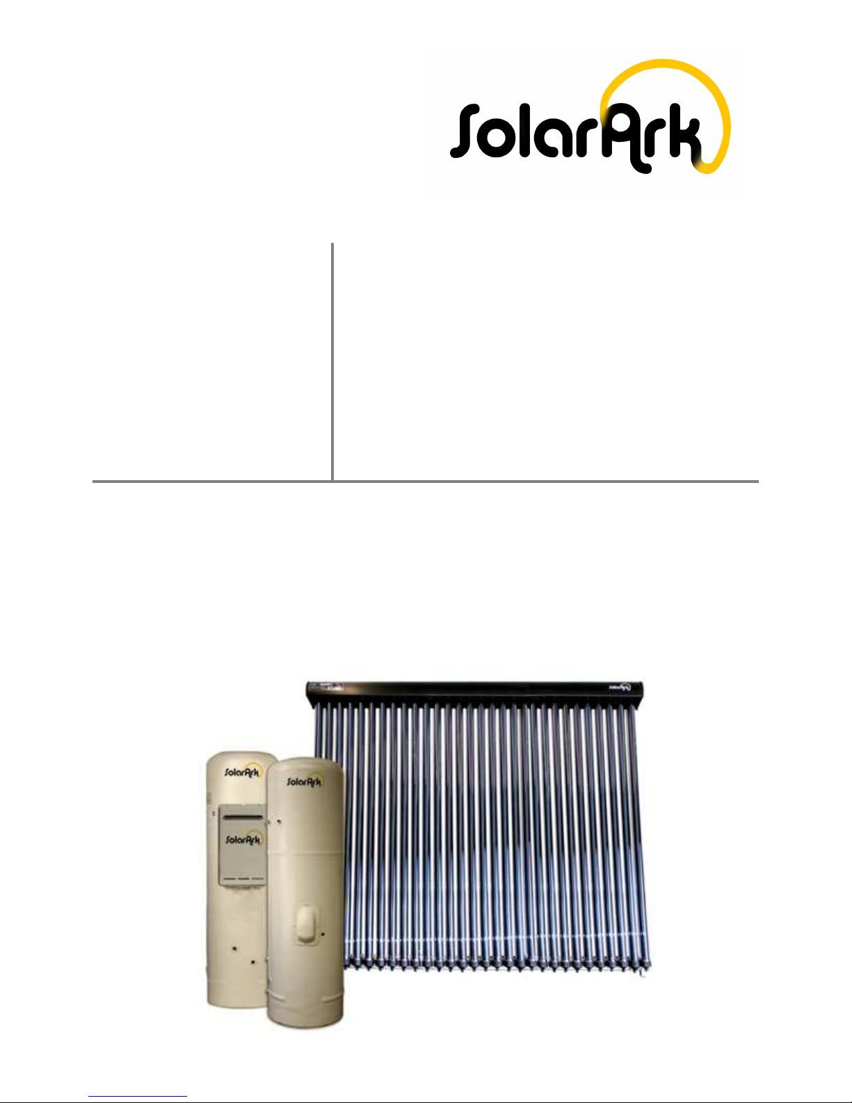
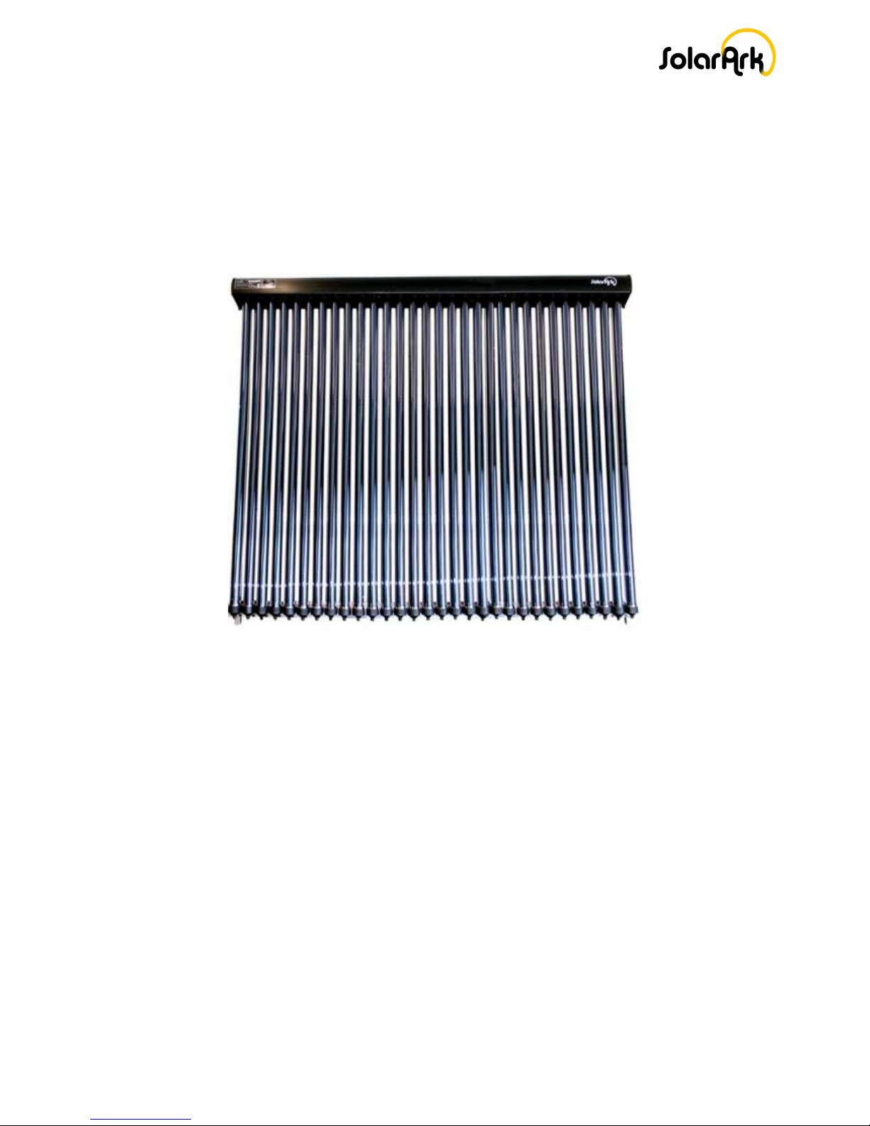
Thank you or your decision to purchase a SolarArk Evacuated Tube
Solar Hot Water System.
The content o this manual provides detailed in ormation on
maintenance, troubleshooting, sa ety precautions and warranty that
should be thoroughly read and adhered to ollowing installation.
Should you have any questions regarding the in ormation contained,
please contact SolarArk on Ph: 1300 760 966 or support.
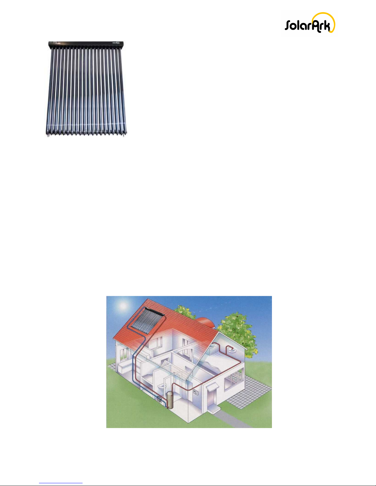
Introduction to Solar Water Heating
The design o the cylindrical evacuated tubes allows maximum absorption o the sun’s energy to
convert it to heat.
The cold water rom the bottom o the storage tank is pumped up to the insulated mani old o the
solar collector, which passes through the heat exchanger. It absorbs the heat and is returned back
to the storage tank.
The controller measures the di erential temperature between the water supply rom the bottom o
the tank and the water return rom the collector to maintain the set temperature within the
storage tank.
The circulating pump operates intermittently throughout the day to maintain maximum hot water
output and minimise energy consumption.
Copyright © SolarArk Installation Manual version 4.6 July 2012 P a g e | 6
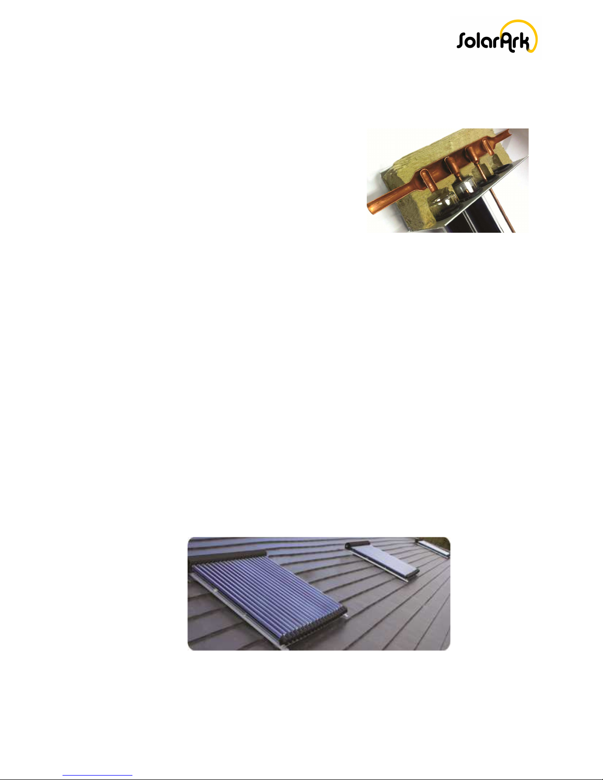
Key Features
SolarArk utilizes copper, aluminium and titanium as part o a three target ilm technology.
This provides excellent heat retention that exceeds other standard tubes by more than 12%.
The diameter o the heat exchanger has been
speci ically designed to maintain low pressure drop.
High density Rockwool insulation is used to ensure
maximum solar heat gain by minimising the amount o
heat loss even in cold temperatures.
The solar controller will maintain the temperature at the bottom o the tank to a pre-set
temperature o 65°C to 70°C. The on/o di erential settings o the controller are designed
to ensure optimum pump cycling as the water in the mani old heats up. I the collector
reaches 8°C hotter than the tank the controller turns the circulating pump on, and o again
once the temperature decreases to 2°C.
SolarArk solar collector tubes and heat exchanger are individually tested or vacuum and
pressure to guarantee high quality and per ormance.
The tubes are designed to withstand hail and high winds, have long lasting per ormance and
are cheap and easy to replace i damaged.
The complete system is lightweight or easy installation and the stainless steel rame is
resilient to corrosion.
SolarArk are proud to provide a 15 year warranty on their complete solar collector.

Copyright © SolarArk Installation Manual version 4.6 July 2012 P a g e | 7
Te pering Your Water Supply
Tempering valves are mandatory throughout Australia. They are to comply with local regulations as
a sa ety device to reduce hot water supply to a maximum o 50°C. AS/NZS 3500.4:2003 details the
requirements o the tempering valve.
The unction o the tempering valve is to reduce the 65-75 degree water leaving your hot water
storage tank and blending it with cold water to achieve 50°C .To reduce the possibility o scalding
the tempering valve must be installed to the hot water supply line incorporating all sanitary
household hot water outlets.
Only a solar rated tempering valve to be used with the SolarArk hot water system.
Tempering valve should be inspected and correctly adjusted every year, replaced every ive years.
All adjustments o a tempering valve should only be carried out by a licensed plumber.
Boosting Options
For further procedures please follow gas booster model instructions.
NOTE:
When using a direct low system in high mineral content water areas (hard water), scale may orm
in the solar loop reducing collector per ormance and increasing pressure drop that may also render
the system inoperable due to low restriction.
It is recommended in such areas a water treatment system be installed to remove scale orming
minerals or prevent scale layers rom orming.
Gas Boosted
Copyright © SolarArk Installation Manual version 4.6 July 2012 P a g e | 8
During periods o low solar contribution, gas or electric boosting is required to maintain 60°
temperature.
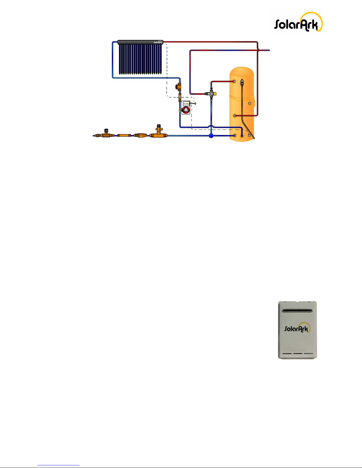
Gas Boosting
The instantaneous gas booster is activated i the water passing through is less than 55°C. The gas
booster will automatically turn o when boosting is not required, there ore increases energy
e iciency.
The gas booster is designed or outdoor installation and can be mounted on the storage tank or on
the wall within a short distance o the storage tank. For indoor installation an indoor lued model
can be used. I wall mounting is used insure that the piping rom the storage tank to the gas booster
is as short as possible and well insulated without any exposed section.
Points to Note:
The gas booster operates when there is a minimum o low rate o 2.4 l/m o hot water
lowing through the booster. The use o water saving devices that have
less than 9lpm low rate or that have restrictors may inter ere with the
operation. To ensure operation, open the hot tap ully to check i the
gas booster comes on.
The S20 gas booster requires a minimum o 120 KPa water pressure
and the S26 requires a minimum o 160 KPa water pressure to achieve
the maximum low rate and optimal unction. I the pressure is less
than the required pressure, a water pressure pump should be installed.
Instantaneous gas booster electronic temperature controllers will not work with SolarArk
systems and are not to be used.
Copyright © SolarArk Installation Manual version 4.6 July 2012 P a g e | 9
Water Flow
S21 or S26 hot water gas boosters have limited hot water low due to the low rate o the gas
booster (21 or 26 litres per minute).
To ensure that your instantaneous unit unctions e ectively, it is advisable to use a AAA rated
showerhead with a minimum low o 9 l/m. It is also recommended to periodically check
showerhead or any debris or deposit built-ups as this may a ect water low and temperature.
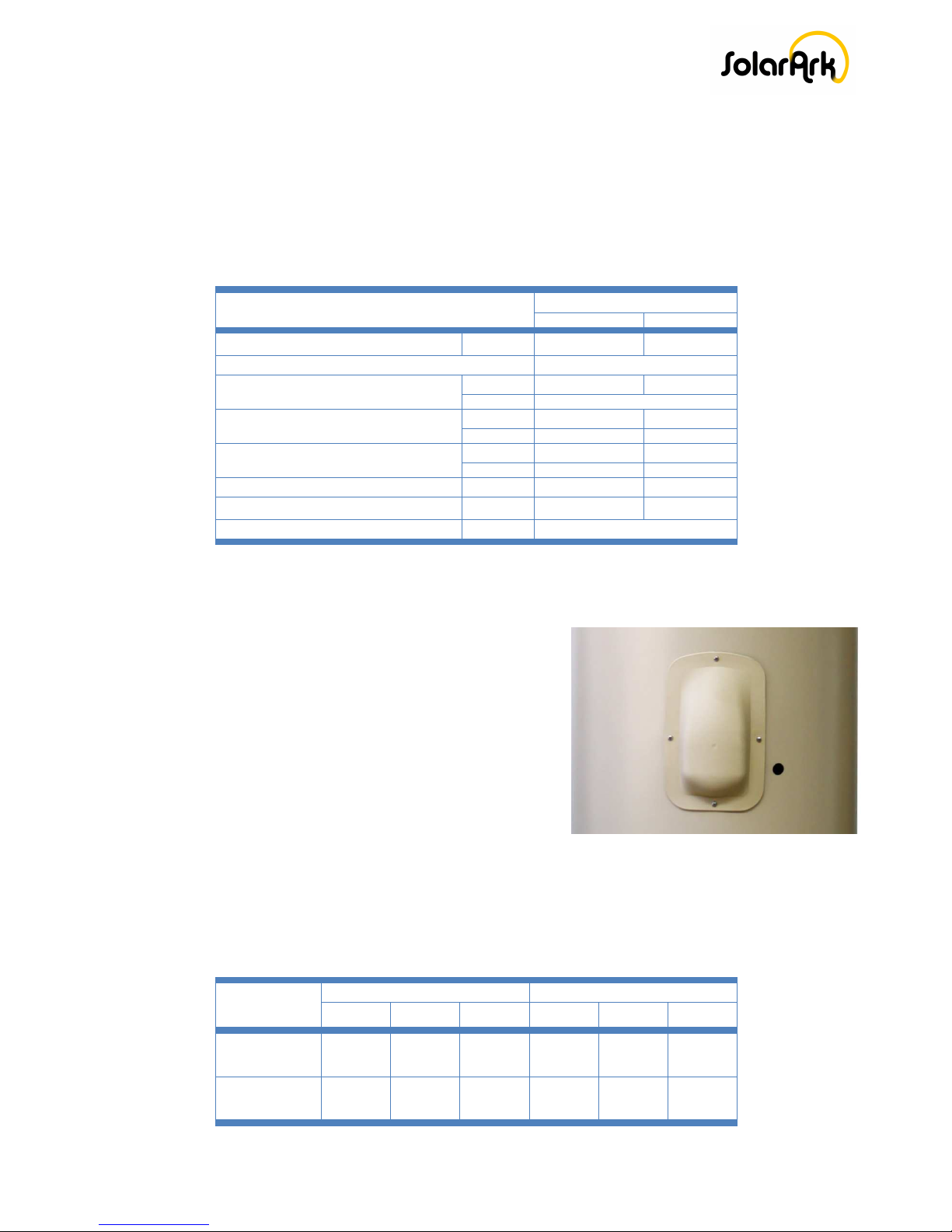
Model Na e
Model Nu ber
S20
S26
Factory Default Te p
°C
70
7
0
Colour
Dune
Water Pressure (kPa)
Min
120
160
Max
1000
Gas Rate LPG (Mj/hr)
Min
11.3
14.7
Max
125
188
Gas Rate NG (Mj/hr)
Min
10.9
13.8
Max
125
188
Flow Rate 25°C Rise (lp )
Min
16
24
Flow Rate Max (lp )
Max
20
26
Connection Sizes Gas/Hot/Cold
( )
20/20/20
Electric Boosting
An electric boosted water cylinder is supplied with a 3.6kW
electric boosting element as standard. The thermostat is set
to 60°C. I the solar contribution is low, the electric boosting
element will activate to compensate or heat loss.
Generally, the required heating time would occur overnight
during the o -peak Tari . I o -peak is not available, the
continuous Tari will require an automatic timer setting to
be activated early evening or overnight when solar radiation
is at its lowest. Depending on the water usage pattern the
timer can be operated manually to activate boosting as you need it to avoid running out o hot
water, however it may take 3-4 hours to heat your water.
Water Delivery & Recovery Rates
Delivery /
Recovery Rate
Gas Boosted Electric Boosted
250L - S21 315 – S21 315L – S26 S160L S250L S315L
Available Water
Delivery in First
Hour ( Litres)
873 936 1089 210 330 395
Hot Water
Recovery for 50⁰C
rise (litres)
609 609 762 80 80 80

Copyright © SolarArk Installation Manual version 4.6 July 2012 P a g e | 10
Local Standards
Installation must be completed in accordance with the requirements o AS/NZS 3500.4
(AS/NZS3500.4.2 “National Plumbing and Drainage Code Hot Water Supply Systems – Acceptable
Solutions”), or in New Zealand, Clause G12 o the New Zealand Building Code, as well as any
relevant local standards and regulations.
SolarArk Accreditations
BSI Benchmark Certi ication is an Australian Company originally established in 1993 to provide
independent certi ication services to companies wishing to achieve ormal recognition o their
management systems. ISO 9001, QS-9000 and ISO 14001 and Product Certi ication.
Accreditation by JAS-ANZ also implies that companies approved by BSI Benchmark Certi ication is
recognised and accepted in each country where JAS-ANZ has signed a Memorandum o
Understanding with other National Accreditation Board.
The Institute or Thermodynamics and Thermal Engineering (ITW) has been working in thermal
solar energy since the early 1970s. In 1993 the Research and Testing Centre or Thermal Solar
Systems (TZS) was established. TZS is the largest testing centre or solar thermal components and
systems in Europe. TZS has long standing established experience in testing the ull spectrum o solar
thermal experience in testing the ull spectrum o solar thermal products as well as in conducting
research and development projects with partners rom research organisations and industry.
SolarArk Syste Co pliance
SolarArk solar hot water system approved to AS/NZS 2712:2007 Solar and Heat Pump Heaters
Design and Construction. The system is designed to allow stagnation when tank maximum
temperature is reach without dumping a large amount o water rom the TPRV.
All SolarArk evacuated tubes solar collectors are modelled to meet the ollowing standards and
requirements or thermal per ormance, energy consumption calculations, potable water
suitability.AS/NZS 2535, AS/NZS 4234:1994, AS/NZS 4020:2005.
All electric and gas storage water heaters are manu actured to Australian Standards AS 1056.1 and
AS 3142.
SolarArk solar collector has been tested to pass the rost tolerance to -15°C level 2 rost protection.
Copyright © SolarArk Installation Manual version 4.6 July 2012 P a g e | 11
Authorised Installers
All installation o SolarArk solar hot water systems must be installed and checked by a SolarArk
authorised licensed plumber who holds all relevant quali ications.
Any installation, inspections, repairs or maintenance that is required should only be carried out by a
person authorised by SolarArk Pty Ltd.
Safety Precautions and Legionella
In order to kill Legionella bacteria it is an Australian standards requirement (AS3498-2009) that the
hot water in the storage tank be heated up to at least 60°C on a regular basis, either while in the
storage tank (solar electric) or to 70°C by a post boost (gas continuous low).
Bottom element electric: The hot water storage tank must reach 60°C at least once a week. The
element should be activated at least once weekly during winter months and overcast weather. The
element is located at the bottom o the tank.
Mid element electric: The hot water storage tank must reach 60°C at least once daily. The element
should be activated daily during winter months and overcast weather. The element is located in the
middle o the tank, lowering boosting costs by boosting hal o the tank until the solar unit kicks in
again.
Gas boosted systems: Gas booster must be le t on at all times. It will only boost the water i it is less
than 60°C.
Copyright © SolarArk Installation Manual version 4.6 July 2012 P a g e | 12
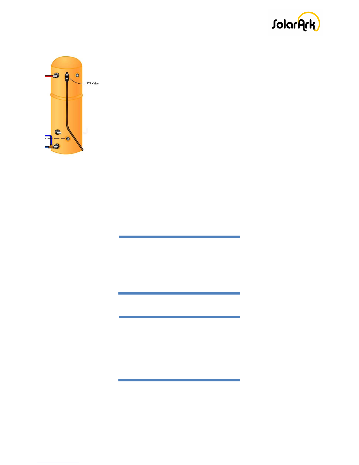
Pressure and Te perature Control and Relief
The pressure & temperature Relie Valve is supplied with the water heater
rom the manu acturer. The valve must be installed into the socket marked
“RELIEF VALVE”. No hot water storage tank should be operated without the
PTRV itted and unctional. The PTRV should be checked or correct
operation or replaced at intervals not exceeding 5 years. .
The lever on the relie valve must be li ted and lowered very slowly to
operate the valve at least once every 6 months. Failure to operate the relie
valve at least once every six (6) months may result in the water heater
exploding.
The relie valve and its drain outlet pipe must not be sealed or blocked.
Water Quality
All hot water storage tanks have been manu actured to suit water conditions o most Australian
metropolitan supplies. Water supplies outside o the speci ications speci ied can have a damaging
e ect on the water heater and its longevity. In ormation can be obtain rom your local water supply
authority regarding water quality details
Water Acceptability Co position Range for Stainless Steel Tanks
Water Quality
Total Dissolved Solids <600 mg/litre or ppm
Total Hardness <200 mg/litre or ppm
Chloride <250 mg/litre or ppm
Sodium <150 mg/litre or ppm
Magnesium <10 mg/litre or ppm
PH Levels 6.5 – 8.5
Electrical Conductivity 850 µS/cm
Water Acceptability Co position Range for Vitreous Ena el Tanks
Water Quality
Total Dissolved Solids <600 mg/litre or ppm
Total Hardness <200 mg/litre or ppm
Chloride <300 mg/litre or ppm
Sodium <150 mg/litre or ppm
Magnesium <10 mg/litre or ppm
PH Levels 6.5 – 9.5
Calcium 20 mg/Litre
Iron 1 mg/litre
The water heater is designed or use in areas where the Total Dissolved Solids (TDS) content o the
water supply is less than 2500 mg/L. In areas where the TDS exceeds 600mg/L it is possible that the
magnesium alloy anode (supplied in glass lined heaters only) may become over reactive.

Copyright © SolarArk Installation Manual version 4.6 July 2012 P a g e | 13
To alleviate this, the magnesium alloy anode should be replaced with an aluminium alloy anode,
available rom your local plumbing supplier. Water can also be very corrosive, the measure o this
is the saturation index, i the water saturation index is greater than 0.40 an expansion control valve
should be itted and where the index is greater than 0.80 the water heater installed should be a
Hard Water Model. Please consult SolarArk or advice i required. In regions with “hard” water
(<200mg/L or ppm), it is advisable to install a water so tening device. This will ensure the long term
e icient operation o the solar collector.
Corrosion
When high concentrations o chloride are present, both copper and stainless steel are susceptible
to corrosion. There ore, the use o this system to heat chlorinated pool or spa water will void
warranty. SolarArk will not warrant any equipment ailure due to corrosion related damage.
Chloride levels present in most reticulated public potable water supplies are sa e or use in the solar
collector provided there is no use o bore waters in the reticulated supply.
Freeze protection and Snow Loading
The solar collector is protected by a rost protection controller. Evacuated tubes are impenetrable
against damage due to cold weather. A low mani old temperature pump circulation eature turns
the pump on i the mani old temperature drops to 4°C and turns o again when the temperature
rises to 6°C.In areas prone to heavy snow all, the solar collectors should be installed at an angle o
50° or greater to promote snow sliding o the tubes. Each tube is tested to withstand >50kg o
loading.
Water is the most suitable heat trans er luid in regions where reeze protection is not a concern.
A closed loop system should be used in regions subject to reezing temperatures, a ood grade heat
trans er luid to be used normally polypropylene glycol or glycerine based product.
POWER TO THE CONTROLLER SHOULD NEVER BE INTERRUPTED AS IT IS ESSENTIAL FOR THE
OPERATION OF THE FREEZE PROTECTION FEATURE.
WARRANTY WILL BE VOID IF DAMAGE OCCURS DUE TO POWER SUPPLY INTERRUPTED
Hail Resistance
The SolarArk evacuated tubes are able to handle signi icant impact rom hail o up to 25mm/1” in
diameter. The ability o the evacuated tubes to withstand impact rom hail is greatly in luenced by
the angle o impact and so installing collectors at low angles will reduce their impact resistance.
Wind Stress
When installing the SolarArk collector please consider the ollowing points: wind resistance caused
by high strength winds and the stress applied upon attachment points due to these winds. The

Copyright © SolarArk Installation Manual version 4.6 July 2012 P a g e | 14
pitched roo rame and angle rame are designed to withstand high wind speeds without damage.
However the roo attachment points may not be as strong. For areas with the possibility o high
winds, additional arrangements or rein orcing attachment points should be considered.
Lightning Protection
Where the solar collector is installed in an area that is prone to lightning it is recommended to earth the
solar collector copper circulation loop to aid in avoiding lightning related damage and sa ety issues,
installers should re er to the local building codes and regulation regarding lightning protection and
grounding.
Collector Di ensions & Weights
Collector Size:
Gross Weight (Empty):
Absorber Area:
Aperture Area:
Gross Area:
Fluid Capacity:
Overall Width:
Overall Height:
Overall Length:
Distance between Inlet
a
nd Outlet
10 tubes
45 Kg
0.8m²
0.94m²
1.57m²
754ML
810mm
155mm
2000mm
930mm
20 tubes
78Kg
1.6m²
1.88m²
2.96m²
1546ML
1560mm
155mm
2000mm
1680mm
30 tubes
115 Kg
2.4m²
2.82m²
4.35m²
2338ML
2310mm
155mm
2000mm
2435mm
Roof Structural Integrity
Collector weight is minimal and will not cause excessive weight stress on the roo structure. No
rein orcement o the roo structure is required or lush mounted collectors. The SolarArk collectors
weigh approximately 78kg or 20 tubes and 115kg or 30 tubes.
I installing at a raised angle (adjustable rame) in a high wind region, high winds will cause vertical
and horizontal loads on the rame. Please ensure that the roo structure is able to withstand such
orces.
Stagnation and Excess Heat
Evacuated tube solar systems have the ability to heat water well above 100°C during periods o high
solar radiation and minimal hot water usage. The controller has an inbuilt guard against hot water
entering the storage tank. Once the bottom sensor has reached the pre-determined setting o 65°C,
or 70°C (known as TOPOUT) power is no longer sent to the pump. This is needed as it is a
requirement that heat in storage tanks does not exceed 80°C. During these periods o high solar
contribution and minimum hot water usage, the solar collector can generate more heat than is

Copyright © SolarArk Installation Manual version 4.6 July 2012 P a g e | 15
required at these times, the controller will turn o the pump to prevent the tank rom overheating
and the hot water tank temperature will not increase urther, when water is no longer circulating
through the solar collector that would cause stagnation due to the energy still getting absorbed and
not getting used, the temperature will rise in the mani old there or pressure will start to build-up.
In some cases a crackling noise may be heard in the pipes when the hot water tap is opened i
steam had ormed in the solar collector. This noise may occur recurrently i the cold water supply
pressure is low <400 KPa. Installation o a pressure pump may help reduce the occurrence o this
noise.
Not having the pump cycling will cause stagnation in the mani old. This could potentially occur
during periods o high radiation and little to no water usage in the home. Throughout these
conditions the mani old will reach around 160°C. At this temperature the water does not boil as it is
under pressure, the pressure relie valve on the tank is set to 850kPa. This means that the water
would have to reach roughly 180°C be ore any steam could orm. Whenever the hot water in the
home is used pressure in the system will drop equalizing with the water supply pressure which is
normally between 500 to 800 kpa depending on your local water pressure supply and the pressure
limiting valve. Due to that pressure drop steam may orm.
I the pump stops running due to power blackout or pump ailure, a Pressure Temperature Relie
Valve (PTRV) is incorporated into the hot water storage tank as a sa ety precaution which releases
high temperature water and steam rom the tank should it reach 95°C or 850KPa. The PTRV must
have a downward acing copper pipe connected, running expelled water to an appropriate drainage
point. It is important to ensure the relie valve or drain tube not be sealed or blocked. A regular
maintenance check at six month intervals is recommended.
During stagnation conditions or or households with a cold water delivery <400kPa, large amounts
o steam may be ormed in the collector when the hot water tap is opened causing a loud
“banging” sound within the copper pipes and the storage tank. Installing a pressure booster pump
that can achieve >400kpa pressure is recommended. An air eliminator should be installed on the
water return outlet o the solar collector to help reduce or eliminate this problem. This is applicable
or installations with main water supply or tank water. A check valve must also be installed on the
cold main line be ore the tank.
I noises is heard when hot water is not used that may indicate a ault with the cold water supply
check valve (duo-valve) or check valve not installed. A check valve must be installed to allow the
system to operate at high pressure and prevents hot water lowing back down the cold water inlet
line damaging low temperature rated components.
SolarArk can provide a closed loop system or application with low water pressure situation to
eliminate the noisy piping, as a closed loop system is not governed by the water supply pressure it
has a constant pressure with an independent pressure relie valve rated at 850kpa. Solar loop has
an operating pressure between 650 to 750kpa.

Copyright © SolarArk Installation Manual version 4.6 July 2012 P a g e | 16
Water Boiling Point
When operating a hot water system under pressure the boiling point at which the water will turn to
steam will change as per the ollowing chart.
Auto atic Air Eli inator
An automatic air eliminator should be installed on the solar collector to provide an escape point or
any air that may be trapped in the solar loop supply and return lines. It will aid in preventing the
solar collector rom overheating in high levels o solar gain and low water usage also in the event o
a power outage.
An automatic air eliminator should also be installed or systems with low water pressure supply and
systems with water supply booster pumps to aid in venting steam rom the solar collector mani old.
Piping Connection and Valves
Only well insulated copper piping to be used or solar low and return lines as per AS/NZS
3500.4:2003 Section 8 details insulation requirements. Any material used or the solar loop must be
appropriately rated or high temperatures and operating pressures that a SolarArk system capable
o producing in normal and high stagnation conditions. Fitting should be temperature rated to
>180°C. Component within a 50cm o collector inlet or out let should be >230°C rated.
Always use copper or brass ittings or the installation o a SolarArk solar hot water system never
use plastic olives or synthetic piping.
Brazing copper piping directly to mani old ports is not recommended as brazing may damage
rubber components on solar collector header .do not over tighten or twist the copper piping on
mani old that could also cause damage only use brass compression ittings supplied.
There are two 22mm ports on the mani old o the solar collector both ports have a 6mm sensor
well located near them that can be used or inlet or outlet. The roo sensor should be installed on
mani old outlet (solar return) an air eliminator also to be installed on solar return.
Gauge Pressure KPa Boiling Point °C
0 100
100 120
200 133
300 143
400 152
500 159
600 165
700 170
800 175
850 177

Copyright © SolarArk Installation Manual version 4.6 July 2012 P a g e | 17
There are two compression ittings supplied with the solar collector mani old 22mm compression to
½ inch lare connection i connecting multiple collectors or commercial applications a 22mm
compression to ¾ BSP brass ittings may be used. Only Australian standard approved brass ittings
should be used. For domestic heating application up to 60 tubes DN 15 / ½” copper piping can be
used.
For applications above 60 tubes or with a pipe run longer the 40m o combined low and return
lines it is recommended the use o DN18 / 3/4” copper piping.
Applications with the use o multiple collectors a speci ied pipe size should be used based on the
low rate and pressure props o the system.
Flexible connection should always be used when connecting multiple collectors to avoid damage
due to expansion and contraction o the copper header with temperature changes.
Flow control valve should be used to insure the correct solar loop water low. The system
per ormance is based on the correct water low passing through the solar collector and returning to
the hot water storage tank.
An expansion control valve (ECV) can be installed as it limits the maximum pressure in pressurised,
unvented water heating systems by reliving excess pressure to an approved drain point.700KPa
rated ECV should be used.
Expansion control valve to be installed on the cold water supply into the hot water storage tank.
One o the bene its o installing an expansion control valve, it releases pressure at the cold water
supply saving energy by not purging heated water. It is mandatory to install an expansion control
valve in some states in Australia where the water heater is installed in scaling water area. It is also
mandatory to install a non return and an isolating valve or the installation o pressurised water
heaters throughout Australia.
A combined non return isolating valve can be installed to prevent the back low o water rom a
water heater to the main cold water supply. This serves the dual purpose o protecting the mains
supply rom contamination and the loss o water that has already been heated. The isolating valve
component is use ul as a means o controlling inlet water supply to unvented storage water
heaters.
A pressure limiting valve o 500-550KPa must be itted to reduce the main water supply pressure to
protect the storage tank rom damage, ailure to install a pressure limiting valve will void the
warranty .
Pip
e
Sizing
Reco ended Total Pipe Run Flow +
Return
DN 15
Up to
40 Metres
DN20
Up to
60 Metres

Copyright © SolarArk Installation Manual version 4.6 July 2012 P a g e | 18
For closed loop system an expansion vessel/tank should always be used to prevent the system rom
dumping the heat trans er luid. For domestic use o up to 90 tubes a 10-12L expansion vessel
should be used. The expansion vessel will accept system pressure increase; re er to expansion
vessel manu actures or correct sizing on large systems.

Copyright © SolarArk Installation Manual version 4.6 July 2012 P a g e | 19
Storage Tanks
The storage tank is typically an insulated metal tank with an electric heating element in the bottom
or middle o the tank. Gas boosting is also available as an alternative option to electric boosting.
The storage tanks promote thermal strati ication that prevents incoming cold water rom mixing
with the hot water at the top o the tank.
Gas boosted systems provides optimum energy conservation, as it is only required when the
temperature in the tank alls below 55°C.
A thermostatically controlled electric element in the bottom o the cylinder can be connected to ull
tari or "o Peak" power supply. The heated water rises up the cylinder by natural convection to
the top where it is ready or use. As hot water leaves the storage cylinder, it is replaced by cold
water, which enters at the bottom o the cylinder. SolarArk recommends lushing the water heater
at regular intervals as advised by your licensed plumber lushing will clear any build up solids that
have escaped the line strainer. The tank may be used either indoor or outdoor and should be
installed by and located in accordance with your licensed plumber’s recommendation, but usually
close to the outlet where there is the greatest usage o hot water. Installation must comply with
Australian Standard AS 3500.4 and any local authority regulations.
Galvanic Reaction
Some metals can cause corrosion when in direct contact with one another, Zinc or Zn/AL galvanised
components should not be installed in direct contact with the collectors’ stainless steel rame.
Always use stainless steel roo ing screws along with the rubber rame mounting blocks provided, i
using di erent metals to ix the collector in place always use neoprene washers or contact
separation.
Safety Re inders
•Water heater and control box access covers will expose 240V wiring high risk o
electrocution only to be removed by authorised personnel.
•Care should be taken when handling evacuated glass tubes, i knocked or dropped they may
break. Do not expose the tube to direct sunlight during installation, as the heat pipe will get
very hot in just a short exposure to sunlight.
• Always wear leather gloves and sa ety glasses at all times during installation and
commissioning
•Solar pipes and ittings can reach temperatures o over 100°C extreme care should be taken
when installing or servicing SolarArk solar hot water systems
•I hot water system is not used or two weeks or more, a quantity o highly lammable
hydrogen gas may accumulate in the water heater. To discharge this gas sa ely, it is
recommended to turn on a hot water tap or several minutes until all gas discharge is
ceased. A sink, basin or bath outlet should be used. DO NOT USE THE DISHWASHER, CLOSE

Copyright © SolarArk Installation Manual version 4.6 July 2012 P a g e | 20
WASHER.DRYER OR ANY OTHER APPLIANCE. During this procedure there must be no,
SMOKING OPEN FLAMES OR ANY ELECTRICAL APPIANCES OPERATING NEARBY. I hydrogen
is discharged through a tap similar to air escaping noise will be herd.
• All sa ety percussion should be taken be ore any parts o the installation are started.
Tanks – Stainless Steel
Stainless steel storage tank can be heated using “ ull” or "o -peak" Tari electricity.
Long li e marine grade stainless steel capable o handling high temporisers up to
95°C
The latest aspects o design and material selection include:
Hi-grade stainless steel cylinder
Control o thermal strati ication
Dual Positive Domed Cylinder resulting in optimum location o element(s)
water supply and delivery and lushing-through o suspended solids
Highest level o insulation due to the use o a polymeric external casing
combined with thick polyurethane insulation
Tanks – Vitreous Ena el (Glass Lined)
The Vitreous Enamel (glass lined) tanks are an e icient option or water
heaters. Some eatures include:
Glass lined tanks have a magnesium sacri icial anode that ensures
potable water quality. Suitable to poor water quality areas as an
aluminium anode can be installed to extend the li e o the tank.
The release o hydrogen can sometimes occur i the water is not used or
long periods o time. To combat hydrogen built up, all water heaters
have a pressure and temperature release (PTR) valve itted to Australian
Standards.
I the water has been stagnant or two or more weeks, pull the lever on
the PTR valve to “purge” the system or 30 seconds. This will expel any
hydrogen built up. Caution need to be taken when purging as the water
will be HOT.
This manual suits for next models
7
Table of contents
Popular Water System manuals by other brands

Spectra Watermakers
Spectra Watermakers LB-20000 Installation and operating manual

Thermo Scientific
Thermo Scientific Barnstead Nanopure TOC - UV Operation manual

Nalco
Nalco 3D TRASAR Series Installation and operation manual

Auto-Chlor
Auto-Chlor WaterSaver A4 Operation guide

Santevia
Santevia MINA quick start guide

Everpure
Everpure ROM 10 Cartridge EV9273-91 Specification sheet


