Watts Premier 5 SV DELUXE User manual

Page 1
INSTALLATION, OPERATION AND MAINTENANCE MANUAL
5 SV DELUXE
WATTS PREMIER 25
CRO-TFM-5SV
ULTRA 5
RO-TFM-4SV
RO-TFM-5SV
PUR-TEK
Refertoenclosedwarrantyforoperatingparameterstoensureproperusewithyourwatersupply.
WattsPremier, Inc. 1725 W. Williams Drive C-20 Phoenix,AZ 85027
Phone:800-752-5582 www.wattspremier.com Fax: 623-931-0191
Save manual for future reference
MODELS
Warning
Pleasereadcarefullybeforeproceedingwithinstallation. Yourfailuretofollowanyattachedinstructions
oroperating parameters may lead tothe product’sfailureand possible damage toproperty.
SystemTestedandcertifiedbyNSFInternationalagainst ANSI/NSF
Standard 58 for thereduction of claims specified onperformance datasheet.

Page 2
Thankyouforyour purchase of a Premier ReverseOsmosissystem.With proper installation and mainte-
nance,thissystemwillprovideyouwithhighqualitywaterforyearsto come.AllofPremier'swaterenhance-
mentproducts are rigorously tested by independent laboratories forsafety and reliability.If you have any
questionsorconcerns,pleasecontactourcustomerservicedepartmentat1-800-752-5582(outsideUSA
623-931-1977)orrefertoouronlinetroubleshootingatwww.wattspremier.com.
Table of Contents
OperationalParameters........................................................................................................................ 4
ContentsofReverseOsmosisSystem .................................................................................................. 4
ToolsRecommendedForInstallation ..................................................................................................... 4
Drill a Hole for the Faucet in a Porcelain Sink ........................................................................................ 5
PunchaHole for the Faucetina StainlessSteel Sink ............................................................................ 5
FaucetInstallation ................................................................................................................................. 6
AdaptaValve Installation ....................................................................................................................... 7
ReverseOsmosisModule Mounting ...................................................................................................... 7
DrainSaddleInstallation........................................................................................................................ 8
TankTeeInstallation............................................................................................................................... 8
GreenTubeConnection ........................................................................................................................ 9
BlueTubeConnection ........................................................................................................................... 9
BlackTubeConnection ....................................................................................................................... 10
RedTubeConnection.......................................................................................................................... 10
6”FinalFilter Installation...................................................................................................................... 10
10"FinalFilterInstallation.....................................................................................................................11
StartupInstructions ............................................................................................................................. 12
6Month System Maintenance.............................................................................................................. 13
AnnualMaintenance ............................................................................................................................ 14
MembraneMaintenance...................................................................................................................... 15
CheckAir Pressure in theTank............................................................................................................ 16
5Stage Reverse Osmosis System ...................................................................................................... 19
CaliforniaCertification ........................................................................................................................ 21
OtherProductsfrom Watts Premier ..................................................................................................... 22
WarrantyRegistration.........................................................................................................................................25
ServiceRecord ................................................................................................................................... 27
LimitedWarranty.................................................................................................................................................28
Page 3
Hardness: Recommendedhardnessnottoexceed10grainspergallon,or120ppm. Systemwilloperate
with hardness over 10 grains but the membrane life may be shortened.Addition of a water softener may
lengthenthe membranelife.
Do not use with water that is microbiologically unsafe or of unknown quality, without adequate
disinfection before or after the system.
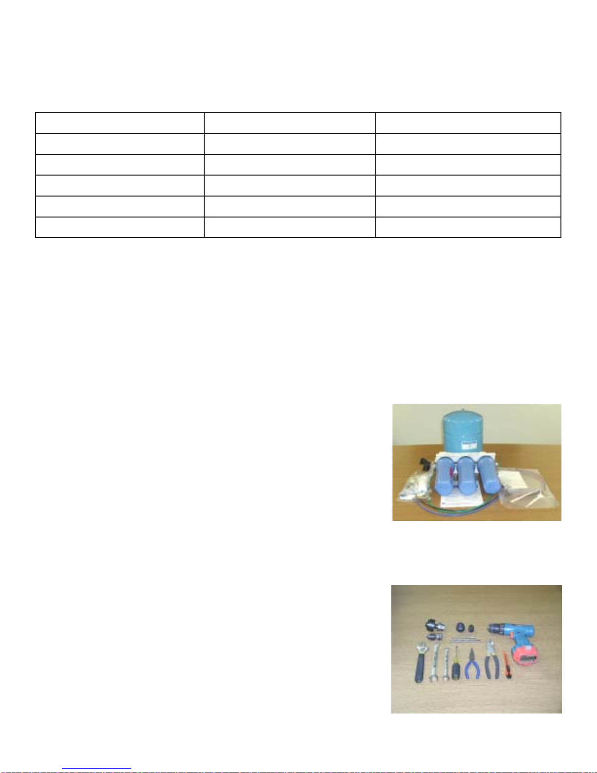
1Tank – Blue or White
1Module – Blueor White
1 Parts Bag – With a 6" or 10" Final Filter
1 Faucet Bag
1Manualand WarrantyCard
5StageRO System has 3 bowls. 4 StageROSystem has twobowls.
If any of the items are missing please contact Premier prior to installing.
Tools Recommended For Installation
√ 1 1/4" Hole Saw Bit for Faucet opening
√Round Knock outPunchfor StainlessSinks,½”& 1 ¼”
√AdjustableWrench
√ Sharp Knife
√ 1 / 2" - 5/8" Open End Wrenches
√Phillips Screw Driver
√ Needle Nose Pliers –Adjustable Pliers
√ Electric Drill
√ 1/8", 1/4" & 3/8" Drill Bits
Contents of Reverse Osmosis System
:serutarepmeTgnitarepO)C°8.73(F°001mumixaM)C°4.4F°04muminiM
:erusserPgnitarepO)2mc/g34.7(isp001mumixaM)2mc/gk08.2(isp04muminiM
:sretemaraPHp11mumixaM3muminiM
:norImpp2.0mumixaM
:)sdiloSdevlossiDlatoT(SDTmpp0081<
:ytidibruTUTN5<
Note: ReverseOsmosiswatershouldnotberun through copper tubing as the purity of the waterwill
leachcopper and cause an objectionaltaste in water andcausepin holes to formin tubing. Be sure to
followanystate or local regulations.
Operational Parameters
Note: Theoperatingpressure in your homeshouldbe tested over a24hour period to attainthe
maximumpressure. Ifit is above 100 psithena pressure regulator willberequired.
Page 4
Note:
Makesurethesurroundingsofthesinkarecooled before mounting the
faucettothesink after drilling. Remove all sharp edgeswithafile.
Step 3
Step 4
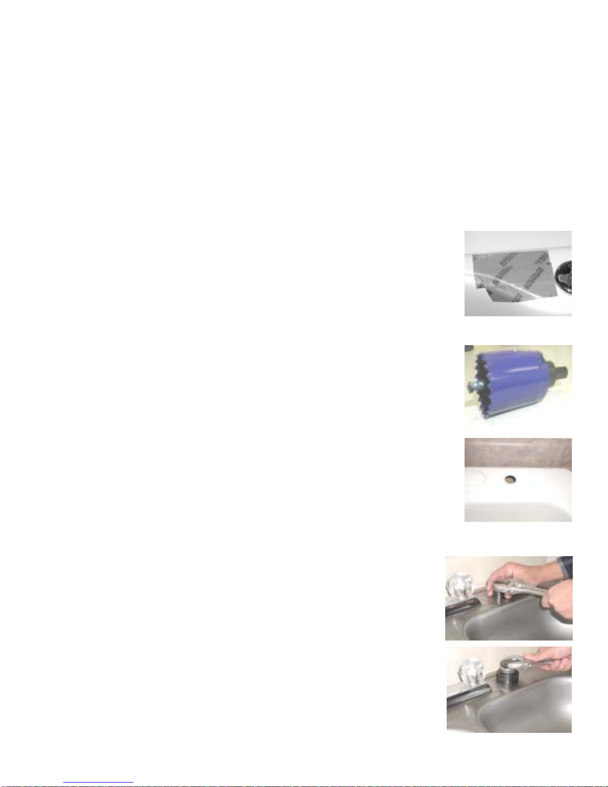
Determinedesired location forthe faucet onyour sink andplace a piece
ofmasking tape on location where the holeis to bedrilled. Mark the
centeroftheholeonthetape.
Step 1
Using a variable speed drill on the slowest speed, drill a 1/8" Pilot
holethroughbothporcelainandmetalcasingofsink at the center of the
desiredlocation. (If drill bit gets hot it maycause the porcelainto crack
orchip).
Using a 1 ¼" hole saw, proceed to drill the large hole. Keep drill speed
on the slowest speed and use lubricating oil or liquid soap to keep the
holesawcoolduring cutting.
Step 2
Drill a Hole for the Faucet in a Porcelain Sink
Porcelainsinksurface material is extremelyhard and can crack orchip quite easily. Use
extremecautionwhendrilling. PremierManufacturedSystemsacceptsnoresponsibilityfor
consequentialdamageresultingfrom the installation of faucet.
Adrippingorgurgling sound may be heard comingfromtheAirGap hole in the faucetwhenthe
systemisrunning. Thisis normal and in compliance withUPCPlumbingCodes.
Most sinks are predrilled with 1 ½" or 1 ¼" diameter holes (if you are already using it for a
sprayer or soap dispenser, see step 1).
See the Faucet Installation section for the proper size hole to drill for a non air gap faucet.
Punch a Hole for the Faucet in a Stainless Steel Sink
Drilla¼”pilothole. Usea½”HolePunchandan adjustable wrench
topunchthe hole in the sink.
Step 5
Thefaucetcannow be installed.
Ifmountingfaucet to a StainlessSteel Sink you willneeda ½" & 1¼"
HolePunch. Thefaucetopeningshouldbecenteredbetweenthe
back splash and the edge of the sink, ideally on the same side as the
verticaldrain pipe.
Note:

Page 5
•Faucetassembly
•BlackShankNut
•Slottedwasher
•Gasket
•3'BlueTube
Ifusingthe WaveAir Gap Faucet (included),a11/4" hole will be required.
Ifusinga Wave non air gapfaucet,a3/4” hole will be required.
Wave Faucet Installation
Removeblackstemnutandinsertthethree tubes (air gap faucet)
throughthewhitegasket withthegrooveonthegaskettowardthe
faucetbase.
Insertthethreetubesthroughthe11/4"hole in the sink. The white gasket
must be on top side of the sink.
Step 6
Step 7
Step 8
GatherandidentifytheWavefaucetpieces.
Viewfromunderthe sink and insert thewhiteplasticspacer as shown. (A
slotted washer is used if it is a non air gap faucet.)
Threadtheblackstemnutbackontothewhitethreadedstemand thighten
within¼”ofplastic spacer. Check theorientationofthefaucetabove the
sinkandtightenthe black plastic washer until white plasticspacerissnug
andfaucetstands securely on top of thesink. (Fora non air gap faucet,
thebluetubewillhavetobepushedinto the faucet fitting at the bottom of
thefaucet. Pushthetubeallthewaytothe“tubestop”insidethefitting.)
Step 9
Step 10
Note:
Air Gap Faucet
Non Air Gap Faucet
Adrippingor gurgling sound maybe heard coming from theair gap hole
onthefaucetorthedrainwhenthesystem is running. This is normal and
incompliancewithUPC(UniversalPlumbing Code).
Note:
•Faucetassembly
•BlackShankNut
•Spacer
•Gasket
Page 6
AG-SS with Monitor Faucet Installation
Step 6
Step 7
Step 8
Gather and identify the M-500 faucet pieces.
Step 10
Note:
Adrippingor gurgling sound may be heardcomingfrom the air gap holeonthefaucet or
the drain when the system is running. This is normal and in compliance with UPC
(UniversalPlumbingCode)requirements.
If using the AG-SS MonitorAir Gap Faucet , a 1 1/4" hole will be
required.
Remove Faucet and small parts from plastic bag.
Slip the Gasket over the threaded Stem to the Faucet Flange.
From above the sink, feed the tubing and Faucet Stem down
through the 1¼ inch mounting hole in the Sink.
From below the sink, slide the Tubing Guide up the threaded Stem
and follow it with the Mounting Nut, turning the nut clockwise until
fullytightened.
Press the blue colored Product Water Tubing, coming
from the RO purification system into the end of the
threaded Stem. Push it all the way in and then pull on it
firmly to verify it is locked in place.
Refer to Black Tube Connection and Red Tube
Connection steps in this manual to complete the faucet
installation.
.
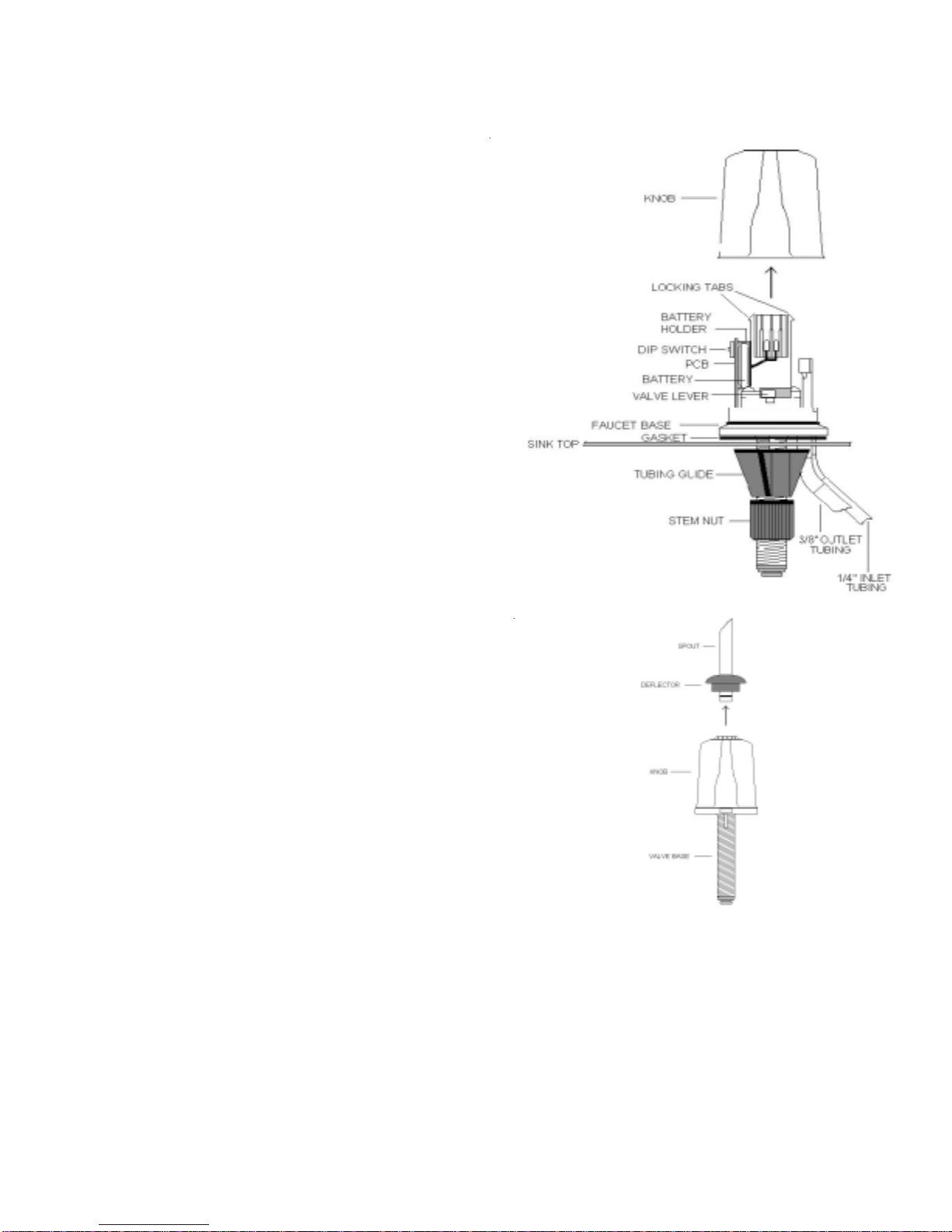
Remove the Spout from the top of the Faucet by pulling it straight
upward.SEE DRAWING
Remove the Faucet Knob by pinching the two locking tabs inward
and then pulling upward on the Knob while the tabs are pinched
inward. Push the coin cell Battery into the Battery Holder behind the
Circuit Board. NOTE: the + side of the Battery goes against the
Gold metal bracket.
Replace the Knob by centering it over the Faucet and aligning the
troughontheinsideoftheFaucetKnobwiththeValveLever.
LowertheKnobmakingsuretheValve Lever slides into the trough,
making sure the Knob top hole is centered over the locking tabs.
Push the Knob all the way down until it locks in place.
Push the Spout back into the top of the Faucet so that it is fully
seated and push the frosted Deflector down until fully seated. You
may have to rotate the Deflector until it is in position to be fully
seated.
With the Knob rotated to the Right about ½ inch, turn the source
water to your RO purification system on and check for leaks. You
should see the Green light flash at the base of the Faucet while water
is flowing through the Faucet (red light may flash when system is
initially producing water, this will turn green following the
initial tank flush). When you see the Red light flash, it means it is
time to replace your filter cartridge(s).
Turn the Knob to the left until water stops flowing and check for leaks.
Step 9
Step 11
Step 12
Step 13
Note:
Page 7
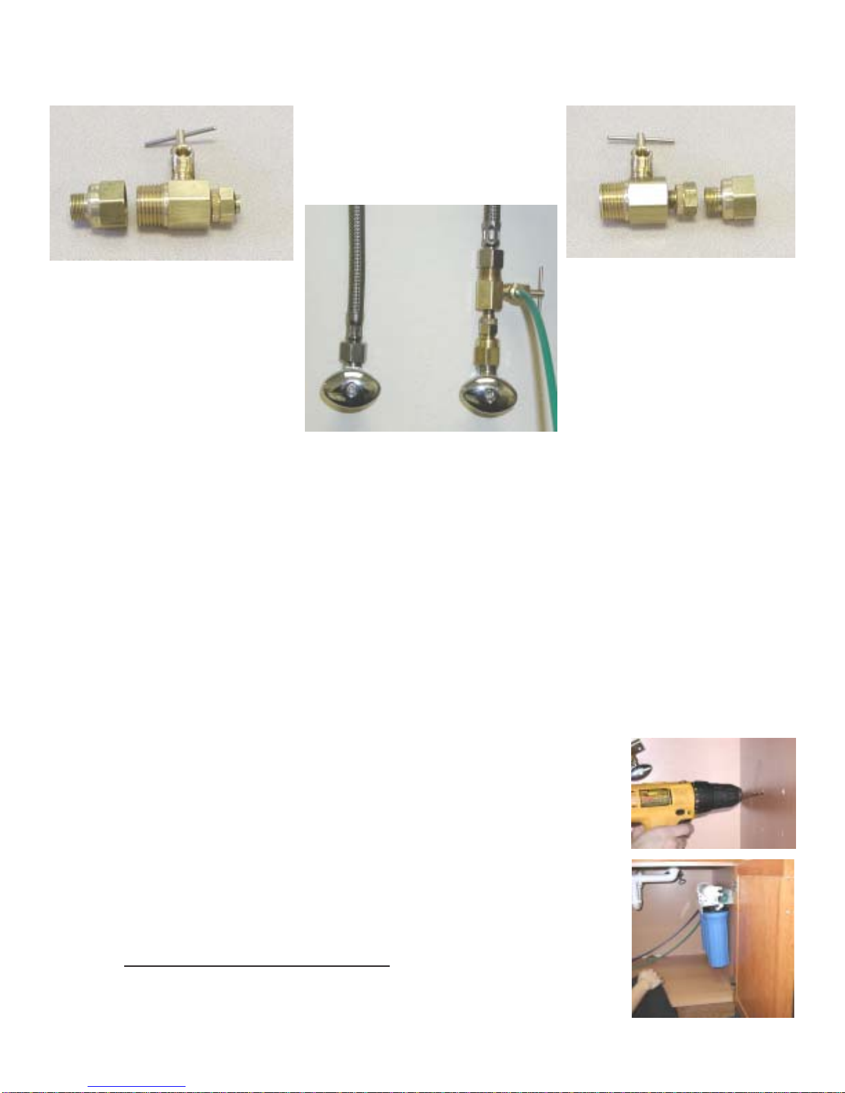
Adapta Valve Installation
Turnoffthecoldwatersupply to thefaucetbyturningtheanglestop valve
completelyoff.
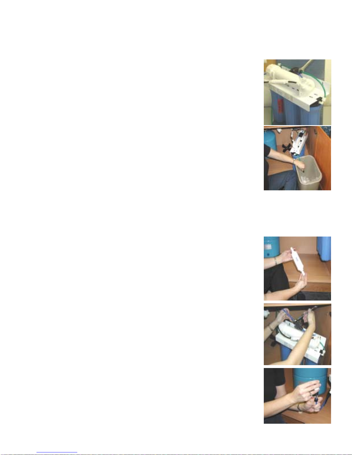
Reverse Osmosis Module Mounting
Step 13 Determinebestlocation for the RO module tobemounted to allow for
futuresystemmaintenance. Thepartsbaghas2 self tapping screws.
Usingaphillipsscrewdriver,screw them into the cabinet wall10¾”
apartand16" from the bottomofthe cabinet.
Step 11
Step 12 Attachadaptavalveasillustrated in the three photos above, choosing the
configurationthatfits your plumbing. (When attaching theadaptavalveto
straightpipe threads, useTeflon tapeon the treads.) The green tubefrominlet side of RO
modulewillbecuttolengthandattachedlater intheinstallation.
Do not cut these tubes at this timeNote:
Caution: Watersupplylinetothesystemmustbefromthecoldwatersupply line. Hot water will
severelydamage your system.
Configurationfor3/8”
compressionfittings Configurationfor1/2”
compressionfittings

Page 8
Drain Saddle fits standard 1 ¼” – 1 ½” drain pipes
Drain Saddle Installation
Step 14
Step 15
Step 16
Threadthebrass tee (supplied intheparts bag) onto the brass
connectiononthetop of tank. Tightenusinganadjustablewrench.
Step 17
Step 18
Teflon tape must be applied in a clockwise direction. Wrap (7 to 12
turns)aroundthemalepipethreads(MPT)ontheStainlessSteel
fittingontop of the tank.
Drilla¼” hole through the drainpipeatleast 1 ½” above thenutof
theP-traptoallowfortheremoval of the P-trap if necessary.
Assemble the drain saddle around the drain pipe. Position the
drainsaddleover the drilled hole in pipe. Insertscrewdriver into
theopeningof the drain saddle andalignwith drilled hole in drain
pipe. UsingPhilipsscrew driver tighten screws evenlyand
securelyon both sides of thedrain saddle. Attachblack
compressionnut,butdonottightenatthistime. The black tubing
willbeinstalledlater.
Thesmallsquare black foam gasket withacircle cut out of themiddle
mustbe applied to the inside of thedrain saddle. Remove sticky tape
backingand stick to thedrain saddle as shown.
1Blackcompression nut
1Semi-circle bracket with opening
2 Screws
1Foam washer
2Nutsforscrews
1 Semi-circle bracket
Gatherthe pieces of the drainsaddle
Tank Tee Installation
Caution: Donotovertightenthescrews. It may crack the drain saddle.
Donotteflontape the compression fitting threads. Iftapeditwill leak.Caution:
Page 9
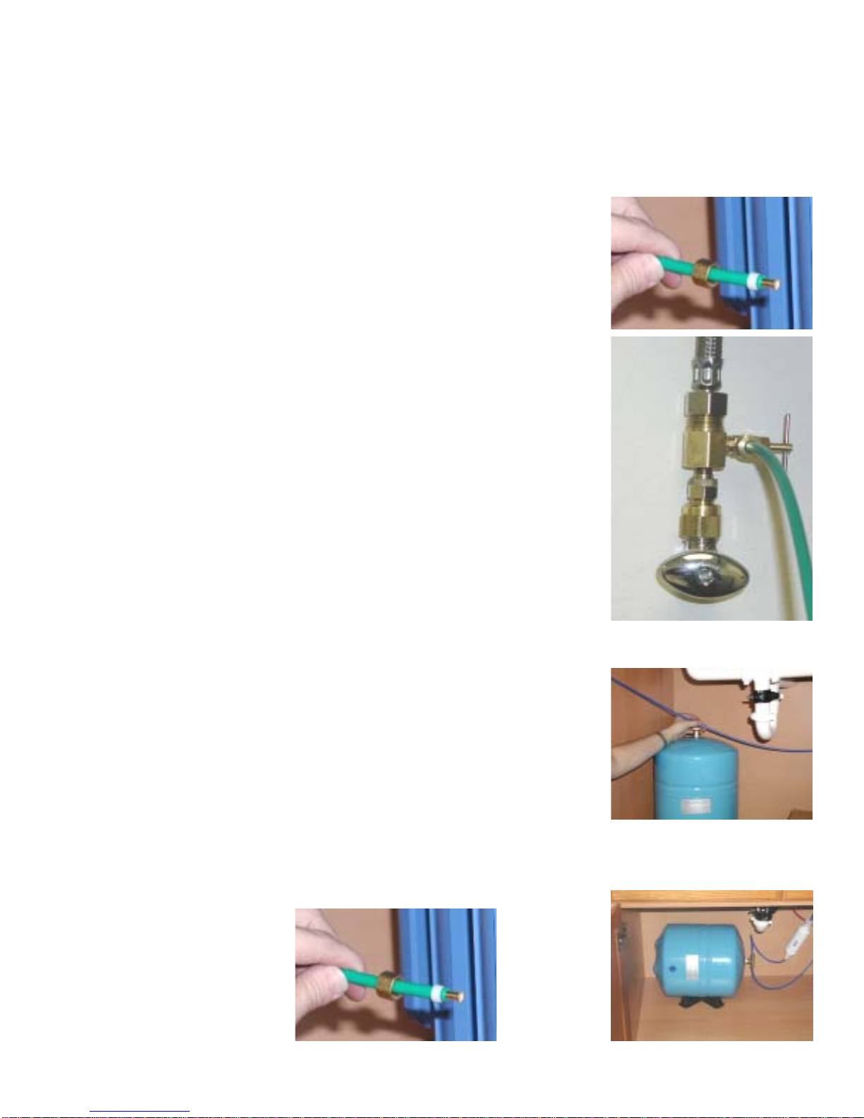
Green Tube Connection
Drape the green tube connected to the 90° Inlet white plastic elbow on the left side of the
Reverse Osmosis Module over to the adapta valve attached to the cold water sink faucet or
attached to the Angle Stop Valve, leaving a gentle curve in the tubing. Cut to desired
length using a sharp knife.
Insertthegreentubeintothe¼”openinguntilit stops. Slide nut
andsleeve down and thread ontothe male pipe threads. Usea
½”wrench tosecurelytighten.
Step 19
Step 21
Blue Tube Connection
Position tank in desired location. Stand it upright or lay it on its
side(usingtheblack plastic stand). Measure the blue tubefrom
theROmoduleovertothe tank and cut it to length.
Removeabrassnut, plastic delrin sleeve and brassinsertfrom
thepartsbag. Placenuton thetube first, then the Delrin sleeve
andtheninsertthe brass Insert into the end of thetube.(Small
taperendofDelrin sleeve must point to the endoftube).
Pushbluetubeinto the brass tee until itstops.Slidebrass nut and
plasticDelrinsleevedown until you can thread nut ontothetee.
Usewrench tosecurelytightenthenut.
Step 20
Step 23
Step 22
Page 10
Black Tube Connection
Measuretheblacktubefrom faucet to the black drain
saddleandmake a straight cutwith a sharp knife
thoughtube.
Removeblack plastic nut from drainsaddle. Slip black tube
throughblacknut. Insert black tube into theopeninginthe
drainsaddleandtightenthe black nut securely.
Thisisa gravity fed line, ifthereisany bend in the tubethe
rinsewaterwillnotflow into the drain properly. Water will back
upand come out the airgap hole in thebackof the faucet
base.
Thetubingmustbeas SHORT and STRAIGHT as possible, making adownwardslopefrom
faucettodrain saddle to allowforproperdrainage.
Step 25
Note:
Step 26
Step 27
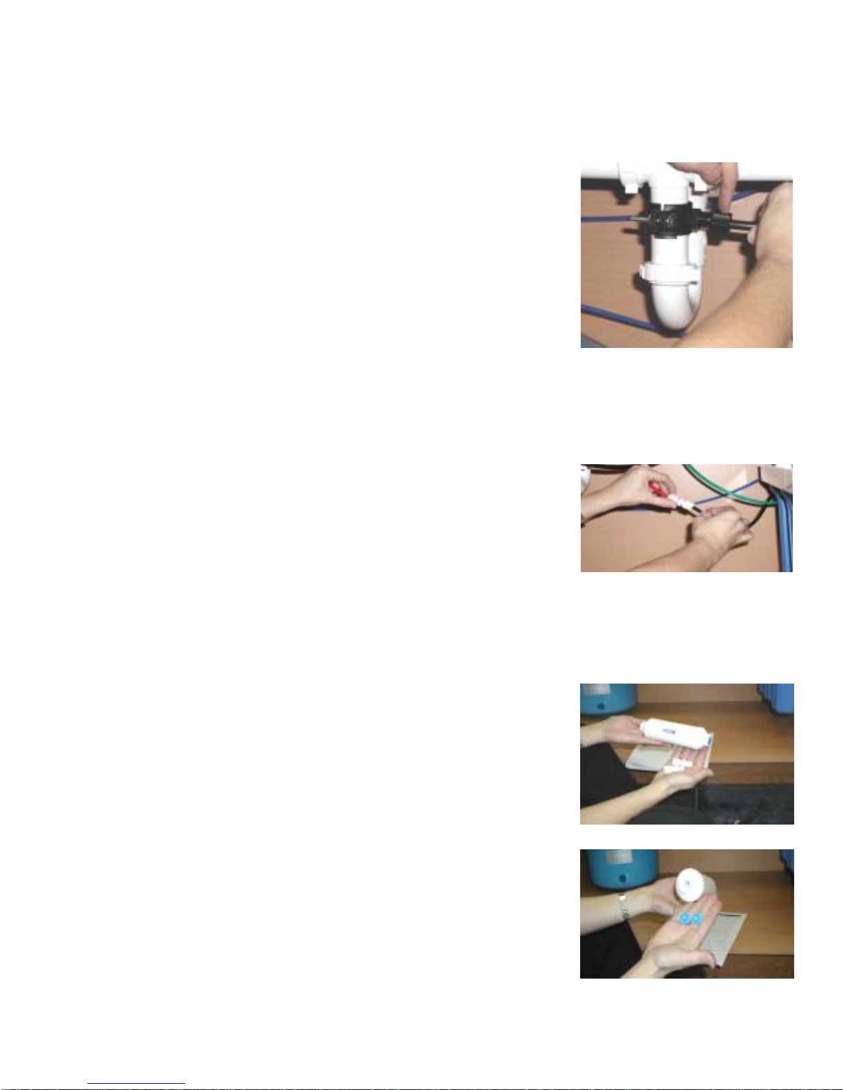
Red Tube Connection
Usingthewhiteplasticunioninthe parts bag, determine where
theredtubingfromthefaucetand theblacktubingfromtheRO
membranehousingwouldjoin together comfortably. Cutthe
tubesleavingastraightcutonbothtubes. Inserttheredtubein
oneendofthewhiteplasticunionand the black tube in the other
end. Usea5/8"wrenchtotightenboth of the white plastic nuts
securely.
Gatherthepieces needed for the Final Filterinstallation. Each
unitissuppliedwith a final filter and 2whiteplasticconnectors.
Removethebluecapsfrom the finalfilter.
6”Final Filter Installation
Step 28
Note:
Step 24
Page 11
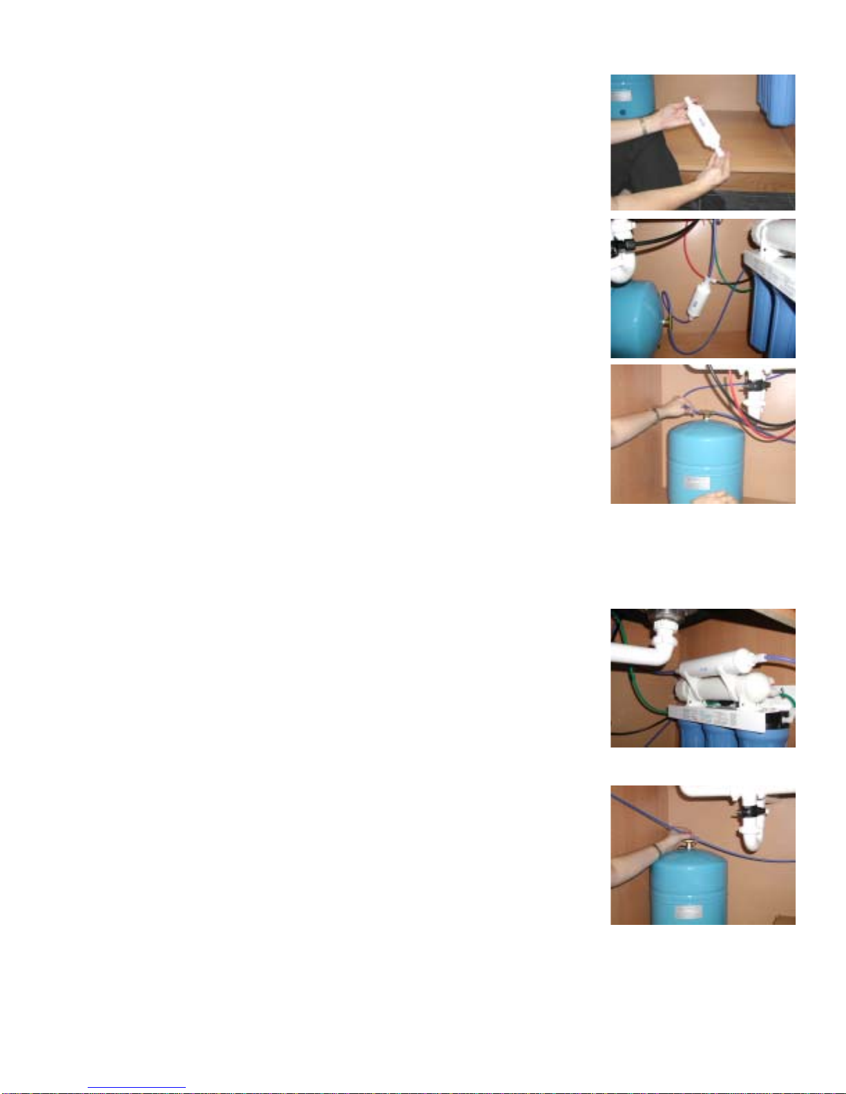
Threadthe2whiteplasticconnectorsintothefinalfilterandtighten.Step 29
Toinstallthe6"filtercutthebluetubefromthefaucetapproximately
inhalf. Insertthebluetube attached to the faucet into the “out” port
ofthefilter. Theflowarrowshouldbepointingtowardthefaucet.
Taketheleftoversectionofblue tube and insert it into the other
whiteconnector.Tightenthewhitecompressionnutswitha5/8"
wrench.
Step 30
Slipthebrassnutoverbluetubingfromfaucet, then slip the white
Delrinsleeveoverthetubingandinsertthe brass insert into the end
ofthebluetubing.(SameasintheGreenTube Connection section.)
Step 31
10" Final Filter Installation
Ifthesystemhasa6"finalfilter, refer to the 6” inch final filter
installation. Ifthe6"finalfilterhasalready been installed skipthis
section.
Removethe2 blue caps from the10" final filter and attachaplastic
connectortoeachendofthefilter.
Step 33
Snapthe 2 white clips fromthe parts bag ontothetop of the
membranevessel. Snapthe 10" final filter into theclips.
Step 32
Measurethebluetubefromthefaucet to the end of the 10" final filter
thattheflow arrow points toward. Useasharp knife to makea
straightcut through thetubing. Insertthetubeinto thewhite
connectorandtightenwith a 5/8" wrench.
Step 34
Insertthetubinginto the brass tank tee until itstops. Slidethebrass
nutanddelrin sleevealongthetubeuntilyou canthreadthenutonto
thetanktee. Use a½”openendwrenchtotightenthenutsecurely.
Note:

Page 12
Start up Instructions
Filloutpostage paid warranty card (phoneno. is necessary for registration)anddrop it in the
mail. Premierusesthis information to provideafree filter change reminderservice. Pre-filters
shouldbechangedeverysixmonths. You may also register your warranty via our website at
www.wattspremier.comor call 1-800-752-5582 (within USAonly).
Step 7
Ifsystemishookedup to an Ice Maker,turnIceMakeroff until tankhasfilled,thenflushedand
refilledbeforeallowingwatertoflowtoIceMaker. The system should have a ball valve
installedbefore the Ice Maker soitcan be closed to prevent waterflowingto the Ice Maker.
Your tankmustbeallowedtofillupinorderfortheunittoshutoff. (Ifyou are installinganIce
MakerKit,teeoffafter the final filter).
Note:
Thetankwilltakebetween4 to 6 hours to fill completely (dependingonthesizeofthe
membrane,localwatertemperatureandpressure).AftertheTankhasfilled,opentheRO
FaucetandflushtheTank completely and to remove carbon particlesfromfinalfilter.
Thereisanaverage of 4 gallons of rejectwaterforevery 1 gallon of product waterproduced.
Step 6
OpentheROfaucetandleaveitopenuntilwater begins to trickle out. (it will come out slowly)Step 5
Turnontheincomingcoldwater. Check the system for leaks and tighten any fitting as
necessary. (Check over the next 24 hourstoensurenoleaksarepresent).
Step 4
Reconnectthegreentube to theAutomatic Shut-OffValveandtightenwith5/8"wrench. (If the
systemishooked up to an IceMakersee the note below.)
Step 3
Turnonthecoldwatersupplyandallowwatertoflowintothebucketuntilthewaterisclear (as
showninthe6monthSystemMaintenancesectionsteps10and11.) Then turn offthe
incomingwatersupply.
Step 2
Disconnectthegreentubethatrunsfromthe3rd StageFilter Housing to theAutomatic Shut- Off
Valve and place it in a bucket.
Step 1
Ifunit is supplied withGAC Carbon Filters (hardplastic case) you willneed to startat step # 1
inthissection. If unit is supplied withCarbonBlockFilters (mesh covering) you mayskipto
Step 4 of this section.
Note:
Inspectthereverseosmosissystemperiodically to ensure the unit is functioning properly.Step 8
Page 13
√One 10” sedimentfilter
√Two10” carbon filters
√Bucket to catch water from filter housings.
√Wrenchtoloosen filter bowls. (WattsPremieralso sells a double sided wrench).
Cleanallfilterhousings(bowls)witha mild soap solution and rinse with
water. CheckO-ringsand lubricate with water soluble lubricant. KYJelly®
andotherwaterbased lubricants can be used, butpetroleumbased
lubricants(such as Vaseline®)mustnotbeused.
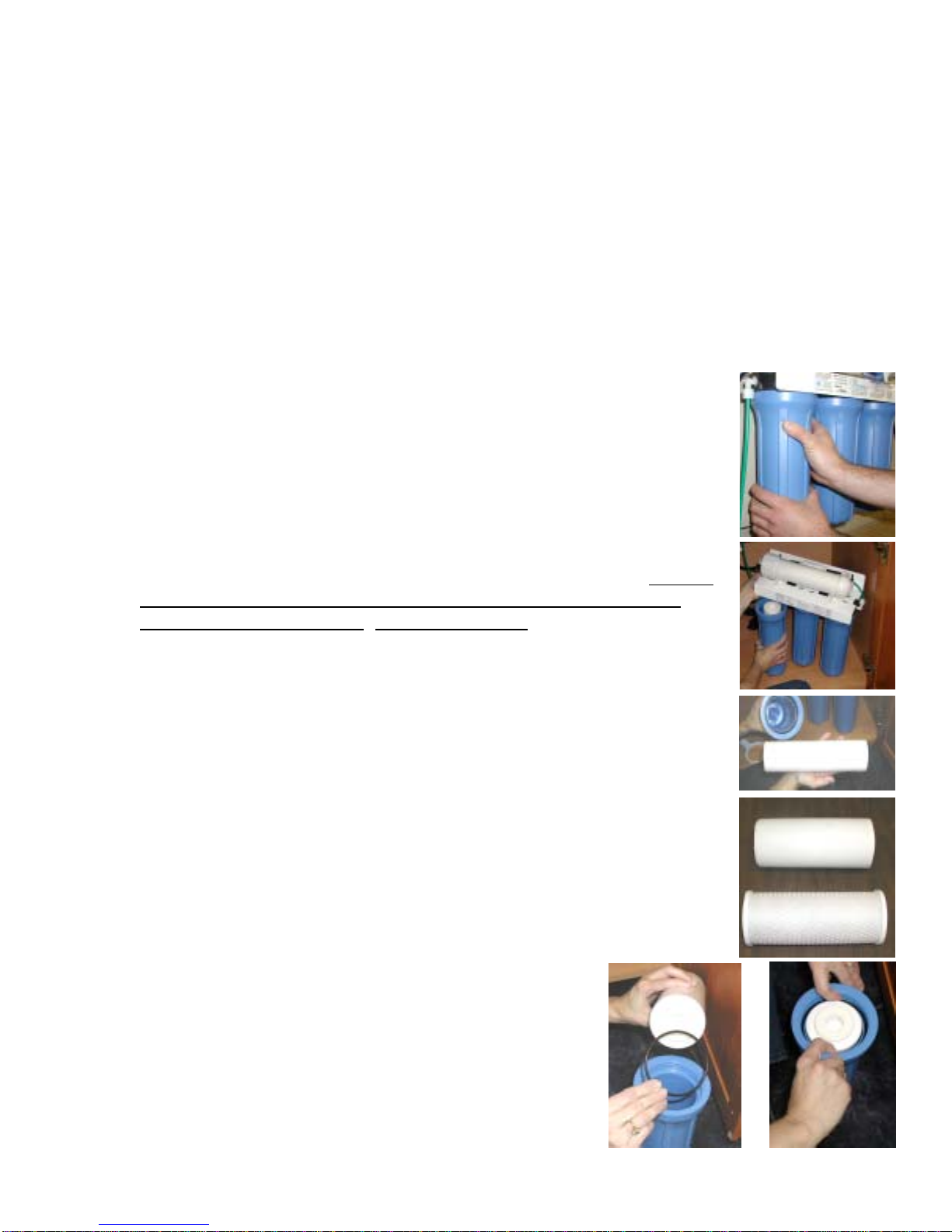
Formoreleverage,leaveROmoduleattached to wall of cabinet. If you are
unabletoaccessthemodule you may remove it to changefilters. Starting
withtheclosesthousing,removeand empty water,thendiscardfilters.
Continueontothe2nd and/or 3rd Bowls.
Thesedimentfilter has a clothlikeappearance. It must be in the1st
Housingonthe left(wherethewaterinletconnects).
6 Month System Maintenance
TurnoffincomingwatersupplytotheRO at needle valve on adaptavalve.
Step 1
Step 3
Step 4
Step 5
Step 6
Letsystem sit for 10 –15 minutes after tankis empty to depressurize beforeattempting to
removefilterhousings.
OpenROFaucettoallowthewatertodrainfromtankuntil completely empty. Watercan
besaved in a container fordrinking or to rinsesystem parts.
Items needed:
GAC Carbon filter is encased in a hard plastic shell and has a white
rubbergasketononeendonly.
CarbonBlockfilter has a meshcovering and a white rubbergasket on
eachend.
KeepROModule in an uprightpositionwhile replacing bowl inorderto
keepO-ringsproperlyseated.
Note:
InserttheCarbonFilter with gasket facing up. (GAC filter
hasa gasket onone end only. Carbon Block filter has a
gasket on each end). Be sure to Seat Black the O-ring
properlyinthe housing bowl.
Step 7
Step 8 Repeatthisstepfor3rd housing(5Stageunitsonly).
Step 2
Page 14
Important: Follow Step 10 –11 only ifyou have GAC (hardplastic carbon filter.)If carbon particles are
notrinsedouttheymayclog theflowrestrictorwhichcould then foul the membrane. The carbon block
filterdoesnotneed to be flushed.
Performsteps4, 5 and 6 inthestart up instruction section.
Holdgreentubeovera bucket. Turnon incoming water atAdapta
Valveand flush out all carbon particlesfromthefilters. Assoon as the
waterrunsclear,turn offtheincomingwaterandre-attachgreen tube to
theAutomaticShut-Off Valve.Usinga5/8" wrench tighten black nut
securely.
Afterchanging pre-filters, disconnect the green tube at theAutomatic
Shut-Off Valve,using a5/8"wrenchtoloosennut.
Step 9
Step 10
Step 11
Annual Maintenance
Watts Premier sells a filterchangekitwhichincludespre-filters,orings, a final filter,connectors, and a
wrench. Call1-800-752-5582orbuyonlineat www.wattspremier.com.
Perform6monthsystemmainenance. (previous section)
TheFinalFiltershouldbereplacedannually. Remove White Nutsat
bothendsof the filter to replace theoldFinal Filter. Replace with new
filterandconnectors.
AnnualSanitizingofunitisrecommendedtopreventbacteriagrowth.
RemovetheBlueTubefromtheleftside of theAutomatic Shut Off
Valve (Marked“OUT”).
Usingaclean eye dropper insert½teaspoon of 3% hydrogenperoxide
orcommonhouseholdbeachintothebluetube. Thiswill flow into the
tankoncewateristurnedback on to unit. Reattach blue tube to
AutomaticShutOff Valve. Followstartup procedure.
Step 1
Step 2
Step 4
Step 5
Note: FlowArrow on final filter must be pointinginthedirectionofthe out flow
ofwater.

Page 15
Membrane Maintenance
Membraneshavealifeexpectancy of between 2 and 5 years,dependingontheincoming water
conditionsandtheamountofuseof the RO system.
Normally, a membrane would be replaced during a semiannual or annual filterchange. However, if at any
timeyou noticeareduction in water production oranunpleasanttastein thereverseosmosiswater, it
could be time to replace the membrane. Asample may be sent into Premier for a free test or a TDS
(totaldesolvedsolids)monitorcan be purchased from WattsPremier to test the incomingandreverse
osmosiswater.
To send awatersample, include ½ cupoftapwater and ½ cup ofthe system’sreverse osmosis water in
cleancontainers.Clearly mark each container. WattsPremierwill test the water and call ormailyouthe
results.
To change the membrane, use a 5/8" wrench to remove the Green
Tubeontheleftside of themembranehousing(theendwithonlyone
elbow).
Removethecap from thewhitehorizontalmembrane housing. Turn
Capcounterclockwiseto loosen.
Usingapair of pliers, grip andpullfirmlyon the membrane to remove
fromthehousinganddiscard.
Unwrapnewmembraneand lubricate the o-rings with water soluble
lubricationsuchasKYJelly® before inserting into housing. Insert
endwiththetwoblackO-rings into the membrane housing.
Oncemembranehasbeeninsertedintothehousingyoumusttake
yourthumbsandgiveafirmpushtoproperlyseatthemembrane.
Replacemembranehousingcapandtighten.
Step 1
Step 2
Step 3
Step 4
Step 5
Adoublesided wrench can be purchasedfromPremier.
Note:
Page 16
To be properly seatedthetip of the Membrane mustbebelow the
housingedge.
Afterreplacingmembranehousingintoclips,attach the green tube to
theelbowoncapusing5/8"wrench.
Theflowrestrictormustbechangedeachtimeyouchangethe
Membrane. Replacetheexistingflowrestrictorwiththenewoneby
removing theWhiteCompression Nuts. Be sure to orientate theFlow
withthearrowpointingtoward the faucet.
Step 8
Step 9
Tip of Membrane
Edge of Housing
Note:
Step 10 Followthe StartUpInstructions.
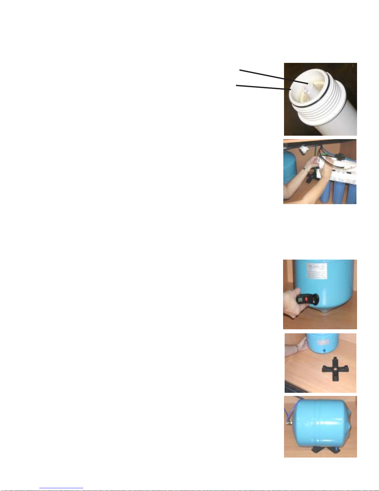
Checkairpressure when tank is empty!
Check Air Pressure in the Tank
Usingadigitalair gauge check the airpressure in the tank. You should
alwayshavebetween 5 -7 psi. If youhavemore than 7 psi releaseair
andrecheck. Ifyou have less than 5 psi,addair. Air can be addedwith
abicyclepump.
Yourunitcomeswithastandfor yourstoragetanktositonifyouneed
toturntheunitonitsside.
Thisallowsforairflowunderthetankkeeping moisture and standing
waterfromrusting on the bottomofyourtankwhichwouldvoidyour
warranty.
Step 1
Step 2
Step 3
Note:
Membrane Maintenance (Continued)

Page 17
TROUBLE SHOOTING
MELBORPESUACSNOITULOS
noitcudorPwolS/woL.1erusserPretaWwoL .erusserpretawgnimocniisp04fomuminimaerussA sierusserpretawemohfipmupretsoobasllesreimerP atpadAdnanodenrutsiylppusretawerusekaM.wol .nepoyawehtllasievlaV
gnibutnispmirC .yrassecensariaperronethgiartsdnagnibutkcehC
sretlif-erpdeggolC.sretlif-erpecalpeR
enarbmemdeluoF.rotcirtseRwolFdnaenarbmemecalpeR
retaWderoloCykliM.2metsysniriA tratslaitinihtiwecnerruccolamronasimetsysehtniriA gnirudraeppasidlliwkoolyklimsihT.metsysORehtfopu retfasruccoernoitidnocfI.skeew2-1nihtiwesulamron .semit2ot1knatniard,segnahcretlif
yltnatsnocretaW.3 tinu/gninnur ffotuhstonlliw
erusserpretawwoLevoba1#eeS
ebutylppusnipmirC .yrassecensariaperronethgiartsdnagnibutkcehC
erusserpretawhgiH tonseodtierusekamoterusserpretawgnimocnikcehC .yrassecenebyamevlavfeilererusserpA.isp08deecxe
nierusserphgiH 5oterusserpriaknatteS.retawfoknategarotsytpmE .egapsuoiverpeeS.isp
niardrotecuafmorfesioN.4tecuafpagriA.stecuafpag-riahtiwdnuostnerehnI
elddasniardfonoitacoL .elddasniardfonoitacolreporprofmargaideeS
ebutniardninoitcirtseR morfsirbedybdesuacsemitemosegakcolbraelC .rehsawhsidrolasopsidegabrag
erusserpretawhgiH .isp08sdeecxeerusserpfideriuqerrotalugererusserP
morfskaeltecuaF.5 erutaefpagriaeht enilniardnipmirC.gnibutkcehC
enilniardninoitcirtseR ynaffotuC.egakcolbraelC.senilniardllanethgiartS .gnibutssecxe
deggolcebutniarD .lasopsidegabragrorehsawhsidmorfdesuaC "8/3ehtnaelc,niardehttaenilkcalb"8/3ehttcennocsiD riagniwolB.tcennoc-erneht,eriwahtiwtuoenilkcalb .golcehtevomersyawlatonlliwenilehthguorht
niretawfotnuomallamS.6 knategarots pugnitratstsujmetsyS woL:etoN.knatllifotsruoh01-6sekattiyllamroN ecuderyllacitsardnacerutarepmetro/dnaerusserp .etarnoitcudorp
erusserpretawwoLevoba1#eeS
reddalbknatniriaevissecxE isp5ebdluohsdnayrotcafehttatessierusserpknaT .isp5evobafideelbdnaisp5wolebfiddA.ytpmenehw .egapsuoiverpeeS.ytpmesiknatnehwylnokcehC
ehtmorfskaelretaW.7 gnisuohretlifetihw/eulb denethgitylreporptoNlwobehtnethgiT
gnirodekniK .erusserpehtesaelerdnaylppusretawehtffonruT dnatietacirbulnehT.yrassecenfigniroehtecalpeR ylreporplwobretlifehtnidetaessigniroehterusekam .lwobretlifehtgnillatsniererofeb

Page 19
Item # Part # Description
16 125041 UNI-PL-1/4CX1/4C
17 131002 NUT-BR-1/4C”
18 131012 SLEEVE-DELRIN-1/4"
19 131017 INSERT-BR-1/4"
20 131021 HEX NIPPLE-BR-1/4 HEAVY DUTY
21 131023 TEE-TANK-BR-1/4CX1/4CX1/4F
22 134002 VALVE-SHUT OFF 1/4MPT (RES.)
23 a 134007 VALVE-ADAPTA VALVE
24 134011 VALVE-CHECK-PLA-ELBOW1/4CX1/8M
25 a 137013 BRACKET-4SV-STEEL-WHITE
25 b 137026 BRACKET-5SV-STEEL-WHITE
26 146001 SCREW-#10-3/4" PHIL PANHEAD
27 146004 SCREW-#10-1" PHIL PANHEAD
28 164006 CLIP-MTG-MEM-VESSEL
29 164010 CLIP-DOUBLE-MEM TO IL (OPTIONAL)
30 164016 DRAIN SADDLE 3/8"
31 119028 TANK STAND
32 113029 O-RING FILTER HOUSING
33 199328 MANUAL 4SV & 5SV PR-14
34 140007 GREEN TUBING
35 140005 BLACK TUBING
36 140004 BLUE TUBING
Item # Part # Description
1 a 100004 GAC-IL-6"-1/4 F (1M-6)
1 b 100014 GAC-IL-10"-1/4 F (PREMIER)
2 104017 SED-SPUN-10"-5M-CTG(5M-10)
3 a 101009 CARBONBLOCK-10"-5M-CTG
3 b 100036 GAC 10” - 56 Cu In CPG
4 a 110004 *MEM-TFM-18 GPD
4 b 110005 *MEM-TFM-25 GPD-DRY
5 a 113004 LID-BLACK 1/4" FPT UNASSEMBLED
5 b 113007 LID-WHITE 1/4" FPT UNASSEMBLED
6 a 113017 HOUSING-FILTER 10" BLUE
6 b 113024 HOUSING-FILTER 10" WHITE
7113032 VESSEL-MEM-HOUSING-RES
8 a 116001 FAUCET-AG-CHROME (TF)
8 b 116002 FAUCET-AG-WAVE BLK ON SS
8c116007 FAUCET-AG-WAVE WHT ON SS
9 a 119004 TANK-PRES-3 GAL-BLUE
9 b 119007 TANK-PRES-3 GAL WHITE
10 a 122004 FLOW RESTRICTOR 150 ML
10 b 122017 FLOW RESTRICTOR 250 ML
11 125002 NUT-PL-1/4C-WHITE-CELCON
12 125005 NUT-PL-1/4C-BLACK-NYLON
13 125017 CON-PL-1/4CX1/4M
14 125031 ELB-PL-1/4CX1/8M-90
15 125034 ELB-PL-1/4CX1/4M-90
* The reverse osmosis system contains a replaceable treatment component, critical for the effective reduction of total
dissolved solids and that the product water shall be tested periodically to verify that the system is performing properly
Parts List for 5 Stage Reverse Osmosis System
Rev 1/31/02
3 32
8
9
20 20
21
22
24
55 5
14
1011 11
12 12
12
12
17
18
19
23
171819
17 18 19
1
30
15
15
28 28
4 7
14
32
3232
BLACK
RED
BLUE
BLUE
BLUE
BLUE
GREEN GREEN
GREEN
Serial # NSF Premier ........
27 26 27
16
25
29
29
31
13
13
BLACK
6 6 6

Page 19
California Certification

Page 20
RECOMMENDED REPLACEMENT PARTS AND CHANGE INTERVALS:
Note: Depending on incoming feed water conditions replacement time frame may vary.
Description Change time Frame Price
Sediment Pre-filter: #5m-10 6 Months $4.50
Carbon Pre-filter: #GAC-410-56/#5MCB 6 Months $9.00/10.50
Final Carbon filter #1m-6/#1M-10 12 Months $9.00/11.95
R.O. Membrane: #TFM-24 2 to 5 years $82.95
This system has been tested according to NSF/ANSI 58 for reduction of the substances below. The concentration of the indicated substances in water
entering the system was reduced to a concentration less than or equal to the permissible limit for water leaving the system as specified in NSF/ANSI 58.
This system has been tested for the treatment of water containing pentavalent arsenic (also known as As (V), As (+5), or arsenate) at concentrations
of 0.30 mg/L or less. This system reduces pentavalent arsenic, but may not remove other forms of arsenic. This system is to be used on water
supplies containing a detectable free chlorine residual at the system inlet or on water supplies that have been demonstrated to contain only pentavalent
arsenic. Treatment with chloramine (combined chlorine) is not sufficient to ensure complete conversion of trivalent arsenic to pentavalent arsenic,
Please see the Arsenic Facts section of the Performance Data Sheet for further information.
Avg. In. Avg. Eff. % Reduction pH Pressure Max Eff. Inf. challenge Max Allowable
concentration concentration
mg/L mg/L
Arsenic (Pentavalent) 334.615 ug/L 5.0385 ug/L 98.4% 50psi 19 ug/L 0.30±10% 0.010 mg/L
Barium Reduction 10.2 mg/L 0.207 mg/L 97.9% 7.24 50psi 0.3 mg/L 10.0±10% 2.0
Cadmium Reduction 0.036 mg/L 0.0005 mg/L 98.6% 7.49 50psi 0.0007 0.03±10% 0005
Chromium (Hexavalent) 0.15 mg/L 0.013 mg/L 91.3% 7.24 50psi 0.03 0.03±10% 0.1
Chromium (Trivalent) 0.17 mg/L .01 mg/L 94.1% 7.24 50psi 0.01 0.03±10% 0.1
Copper Reduction 3.1 mg/L 0.03 mg/L 99.0% 7.64 50psi 0.04 3.0±10% 1.3
Cysts 222,077#/ml 10 #/ml 99.99% 58 minimum 50,000/mL
Fluoride Reduction 8.0 mg/L 0.5 mg/L 93.9% 7.49 50psi 0.7 8.0±10% 1.5
Lead Reduction 0.15 mg/L 0.002 mg/L 98.6% 7.49 50psi 0.003 0.15±10% 0.010
Radium 226/228 25pCi/L 5pCi/L 80.0% 7.24 50psi 5pCi/L 25pCiL±10% 5pCiL
Selenium 0.10 0.008 92.0% 50psi 0.011 0.10±10% 0.05
TDS 96.8% 7.84 750±40mg/L 187
Turbidity 10.2 mg/L 0.26 mg/L 97.5% 0.83 11±1 NTU 0.5 NTU
Note: Depending on water chemistry, water temperature, and water pressure Watts Premier’s R.O. Systems production and performance will vary.
Efficiency rating means the percentage of the total water required to operate the system that is treated and available to the user.
REFER TO OWNER’S INSTALLATION/SERVICE MANUAL FOR FURTHER MAINTENANCE REQUIREMENTS AND WARRANTY INFORMATION.
GENERAL USE CONDITIONS:
1. System to be used with municipal or well water sources treated and tested on regular basis to insure bacteriological safe quality. DO NOT use with
water that is microbiologically unsafe or unknown quality without adequate disinfection before and after the system. Systems certified for cyst
reduction may be used on disinfected water that may contain filterable cysts.
2. Operating Temperature: Maximum: 100°F (40.5°C) Minimum: 40° (4.4°)
3. Operating Water Pressure: Maximum: 100 psi (7.0kg/cm2) Minimum: 40 psi (2.8kg/cm2)
4. pH 3 to 11
5. No iron present in incoming feed water supply.
6. Hardness of more than 7 grains per gallon (120 ppm) may reduce TFM membrane life expectancy.
7. Recommend TDS (Total Dissolved Solids) not to exceed 1800 ppm.
Model No. Avg. Avg. Avg. TDS DPR
Influent Effluent IN/EFF RECOVERY GALLONS EFFICIENCY
TDS TDS REDUCTION
765 mg/l 23mg/l 96.8% 15.5% 9.06gpd 8.35%
Watts Premier Inc.
1725 W. Williams Drive C-20
Phoenix, AZ 85027 USA
California Certification # 00-1452
Watts Premier Product Data Sheet
5 SV Deluxe, CRO-TFM-5SV, Ultra 5 and Pur-Tek, Watts 25, Watts RO-4, Watts RO-5, RO-TFM-4SV, RO-TFM-
This manual suits for next models
6
Table of contents
Other Watts Premier Water System manuals


Popular Water System manuals by other brands

Hog Technologies
Hog Technologies SK5500 Operation manual

Reverse Osmosis
Reverse Osmosis Economy RO75 owner's manual

Yamato
Yamato CF800 instruction manual

Halsey Taylor
Halsey Taylor WCFS G L R Series owner's manual

Alpha
Alpha OKU Instructions for installation, use and maintenance

RadonAway
RadonAway AIRaider EZ95 Installation instructions manual


