Challenger Lifts CLM16-W User manual

Installation, Operation & Maintenance Manual
MOBILE COLUMN LIFT
MODELS CLM16 & CLM16-W
16,000 LBS. CAPACITY PER COLUMN
200 Cabel Street, P.O. Box 3944 Louisville, Kentucky 40201-3944
Email:[email protected] Web site:www.challengerlifts.com
Office 800-648-5438 /502-625-0700 Fax 502-587-1933
IMPORTANT: READ THIS MANUAL COMPLETELY BEFORE
INSTALLING or OPERATING LIFT
CLM16 IOM.DOC 5/8/09

MODELS CLM16 & CLM16-W
OPERATION AND MAINTENANCE MANUAL
CLM16 IOM.DOC 5/8/09
1
Safety
IMPORTANT SAFETY INSTRUCTIONS
1. Thoroughly read all decal and manual instructions before installing, operating or
maintaining the lift. They are provided to prevent personal injury and property damage.
Replace any decal unreadable or missing on your lift.
2. Care must be taken as burns can occur from touching hot parts.
3. Do not operate equipment with a damaged cord or if the equipment has
been dropped or damaged – until it has been examined by a certified
service technician.
4. To reduce the risk of fire, do not operate equipment in the vicinity of open
containers of flammable liquids.
5. Adequate ventilation should be provided when working on operating
internal combustion engines.
6. Keep hair, loose clothing, fingers, and all parts of body away from moving
parts.
7. To reduce the risk of electric shock, do not use on wet surfaces or expose
to rain.
8. Only use your lift as described in this manual. ONLY use manufacturer's recommended
attachments.
9. Only use genuine CHALLENGER replacement parts.
10. Always wear safety glasses. Everyday eyeglasses only have impact resistant
lenses, they are not safety glasses.
11. Inspect your lift daily.
12. Only permit qualified personnel to operate, maintain or repair the lift.
13. Only a CHALLENGER certified installer or technician is allowed to install the lift.
14. Do not allow anyone to climb on lift, stay inside or under vehicle during lift operations.
15. Always keep lift and lift area clean and free of tools, parts, debris, grease etc.
16. Never overload your lift. The rated load capacity is indicated on the lift nameplate.
17. Always use vehicle manufacturer's recommended lift points.
18. Only have Certified CHALLENGER Service Technicians or certified electricians (with prior
written consent of CHALLENGER LIFT, INC.) maintain or repair the electrical equipment.
19. Carefully observe all national and international health and safety regulations.
SAVE THESE INSTRUCTIONS
MODELS CLM16 & CLM16-W
OPERATION AND MAINTENANCE MANUAL
CLM16 IOM.DOC 5/8/09
2
Safety Instructions
SAFETY
INSTRUCTIONS
Read operating and safety manuals before using lift.
SAFETY
INSTRUCTIONS
Proper maintenance and inspection is necessary for
safe operation.
SAFETY
INSTRUCTIONS
Do not operate a damaged lift.
SAFETY
INSTRUCTIONS
If attachments, accessories or configuration modifying
components that are located in the load path, affect operation
of the lift, affect the lift electrical listing or affect intended
vehicle accommodation are used on this lift and, if they are not
certified for use on this lift, then the certification of this lift shall
become null and void. Contact the participant for information
pertaining to certified attachments, accessories or configuration
modifying components.
Cautions
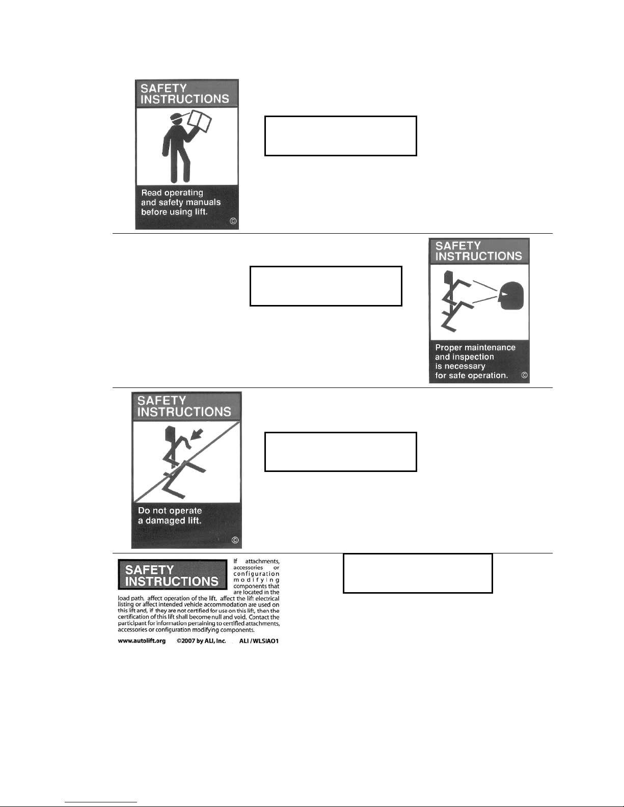
CAUTION
Lift to be used by trained operator only.
CAUTION
Authorized personnel only in lift area.
CAUTION
When moving lift, be careful to avoid tipping.
CLM16 IOM.DOC 5/8/09
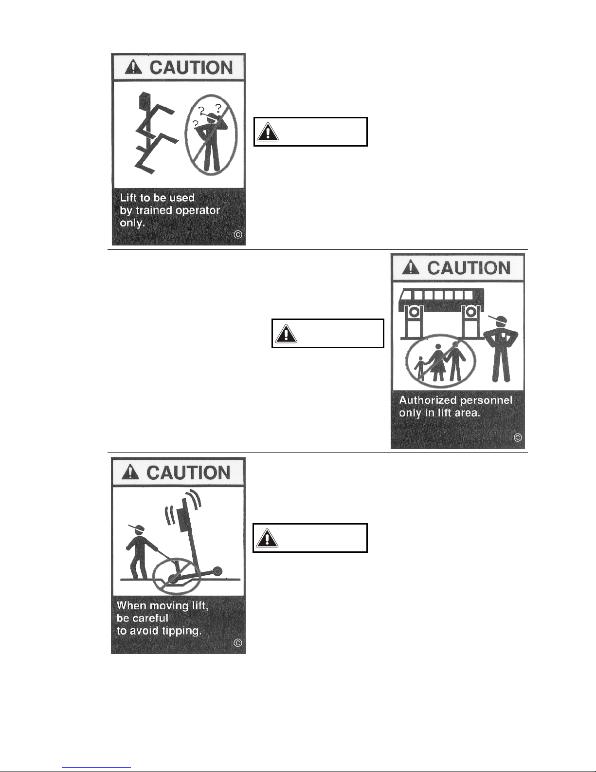
CAUTION
Check for overhead obstructions before raising vehicle.
Warnings
WARNING
Clear area if vehicle is in danger of falling.
WARNING
Remain clear of lift when raising or lowering vehicle.
CLM16 IOM.DOC 5/8/09

WARNING
Locate lift on firm, level surface, preferably concrete.
WARNING
Be sure intended lifts are moving together evenly.
WARNING
All lifting forks must properly engage vehicle tires or
supports.
CLM16 IOM.DOC 5/8/09
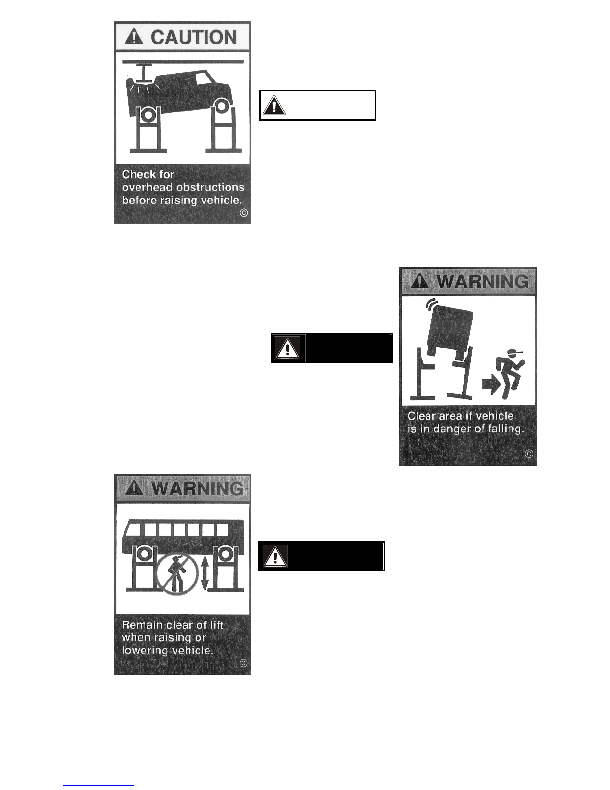
WARNING
Do not drive over or pinch electrical cables.
WARNING
Keep feet clear of lift while lowering.
CLM16 IOM.DOC 5/8/09

CLM16 IOM.DOC 5/8/09
OWNER/EMPLOYER RESPONSIBILITIES
5BLift Operator Qualifications and Training
The owner/employer shall ensure that all lift operators have the appropriate qualifications and that they
are trained in the safe operation of the lift by making use of the following materials: manufacturer
supplied operation & maintenance manual; ALI/SM 93-1, ALI Lifting It Right safety manual; ALI/ST 90
Safety Tips card; ANSI/ALI ALOIM-1994, American National Standard for Automotive Lifts – Safety
Requirements for Operation, Inspection and Maintenance; ALI/WL series, ALI Uniform Warning Label
Decals/Placards; and, if required, ALI/LP-Guide, Vehicle Lifting Points/Quick Reference Guide for Frame
Engaging Lifts.
Operator training shall be appropriately documented in accordance with ANSI/ALI ALOIM-1994.
26BDisplay of Information Materials
The owner/employer shall display the following information materials in a conspicuous location in the lift
area: manufacturer supplied operation & maintenance manual; ALI/SM 93-1, ALI Lifting It Right safety
manual; ALI/ST 90 Safety Tips card; ANSI/ALI ALOIM-1994, American National Standard for
Automotive Lifts – Safety Requirements for Operation, Inspection and Maintenance; ALI/WL series, ALI
Uniform Warning Label Decals/Placards; and, if required, ALI/LP-Guide, Vehicle Lifting Points/Quick
Reference Guide for Frame Engaging Lifts and ANSI/SAE J2184-May2000, Vehicle Lift Points for
Service Garage Lifting.
27BPeriodic Inspection
The owner/employer shall establish a periodic inspection procedure in accordance with the lift
manufacturer's recommendations or ANSI/ALI ALOIM-1994.
The owner/employer shall ensure that all lift inspectors have the appropriate qualifications and that they
are trained in the inspection of the lift.
Periodic inspections shall be appropriately documented in accordance with the manufacturer's
recommendations or ANSI/ALI ALOIM-1994.
28BPeriodic Routine Maintenance
The owner/employer shall establish a routine maintenance procedure in accordance with the lift
manufacturer's recommendations or ANSI/ALI ALOIM-1994.
The owner/employer shall ensure that all routine maintenance personnel have the appropriate
qualifications and that they are trained in the routine maintenance of the lift.
Periodic routine maintenance shall be appropriately documented in accordance with the manufacturer's
recommendations or ANSI/ALI ALOIM-1994.
29BRepair Maintenance
The owner/employer shall perform repair maintenance procedures whenever considered necessary by
lift operator, lift inspector or routine maintenance personnel. Repair maintenance shall be performed in
accordance with the lift manufacturer's recommendations or ANSI/ALI ALOIM-1994.
The owner/employer shall ensure that all repair maintenance personnel have the appropriate
qualifications and that they are trained in the repair maintenance of the lift.
Repair maintenance shall be appropriately documented in accordance with the manufacturer's
recommendations or ANSI/ALI ALOIM-1994.
The owner/employer shall provide appropriate lockout/tagout means for all energy sources in
accordance with ANSI Z 244.1-1982 (R 1993), Safety Requirements for the Lockout/Tagout of Energy
Sources. This shall be done before any repair work is performed.
30BModifications
The owner shall not modify or reconstruct any lift without the manufacturer's express written consent.
Safety Features
WARNING Do not use the lift with any safety devices inoperative !!!
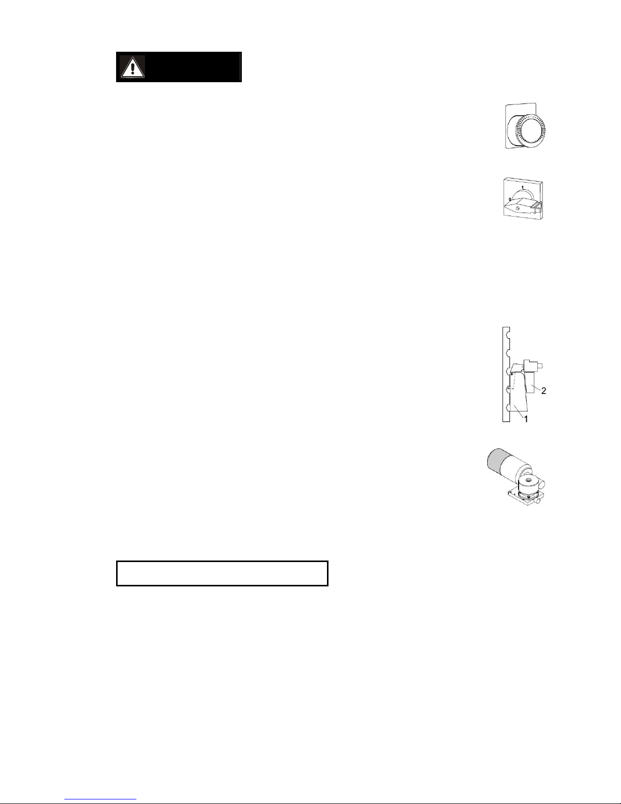
Emergency Stop Button
Serves to disconnect the lift in case of emergency.
Main Switch
Serves to turn the lift ON and OFF.
When in position 0 the switch can be padlocked (also see Lockout/Tag out
Procedure in Maintenance Instructions).
Control Elements
DEAD MAN TYPE CONTROL
The operator is required to hold the switch/button in the engaged position to raise/lower the lift.
CABLE REMOTE CONTROL BUTTONS
The buttons are flush mounted to avoid inadvertent actuation.
Locking Device
The locking device serves to prevent inadvertent lowering motions of the lift
caused by gear, load nut or lifting screw failures. The carriage is blocked by
safety wedge (1) and counterwedge (2).
Electric Drive Motor
The motors are equipped with electrically actuated brakes (plus manual
override). Once the motors are turned off, the brakes engage and prevent any
further lift movements.
Thermal Overload Protection
Overload protection via electronically monitored thermo-switches.
Warning and Information Labels
SAFETY INSTRUCTIONS
Do not change or remove the warning and information labels. Order replacement if
damaged, missing or illegible !!!
CLM16 IOM.DOC 5/8/09
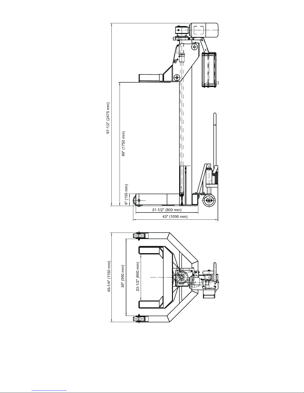
Specifications
CLM16 IOM.DOC 5/8/09
Standard Metric
Rated load capacity (per column) 16,000 lbs 7,273 kg
Raising / Lowering time 113 s
Supply voltage 3~208/230/440/480 V, 60 Hz
Control voltage 24 V
Fuse protection (per column) 7 A @ 208/230V
4 A @ 440/480V
Motor power 2.5 hp 1.8 kW
Weight (per column) 950 lbs 432 kg
Specifications are subject to change without notice.
CAUTION
If the MCL Mobile Column Lifting System contains more than four (4) columns and
is operated at 208/230V, connection cables CC-33-4 or CC-50-4 have to be used !!!
Recommended minimum clearance from lift system including vehicle to nearest
obstruction/wall is five (5) ft.
Ensure adequate clearance above lift to prevent vehicle from making
contact with overhead obstructions.
CLM16 IOM.DOC 5/8/09

Installation
Handling / Location
CAUTION
Make sure the columns are lifted
properly by the structure and NOT by the
carriage.
Make sure all items in use to lift the
column are rated for at least the weight
shown in the specifications.
Screw an eye bolt M16 into the threaded hole
on top of the motor plate of the column. Insert
a chain or strap through the eye and lift the
column using a hoist or forklift.
CAUTION Lift installation by qualified personnel only.
IMPORTANT NOTE:
Lift may be used for both indoor and outdoor applications!
ATTENTION Floor Slope
Ensure that area where columns are installed/used the floor does not slope more than two (2)
degrees in any given direction !!!
ATTENTION Important Information
For further installation information, please refer to ANSI/ALI ALIS, Safety Requirements for
Installation and Service of Automotive Lifts !!!
CLM16 IOM.DOC 5/8/09
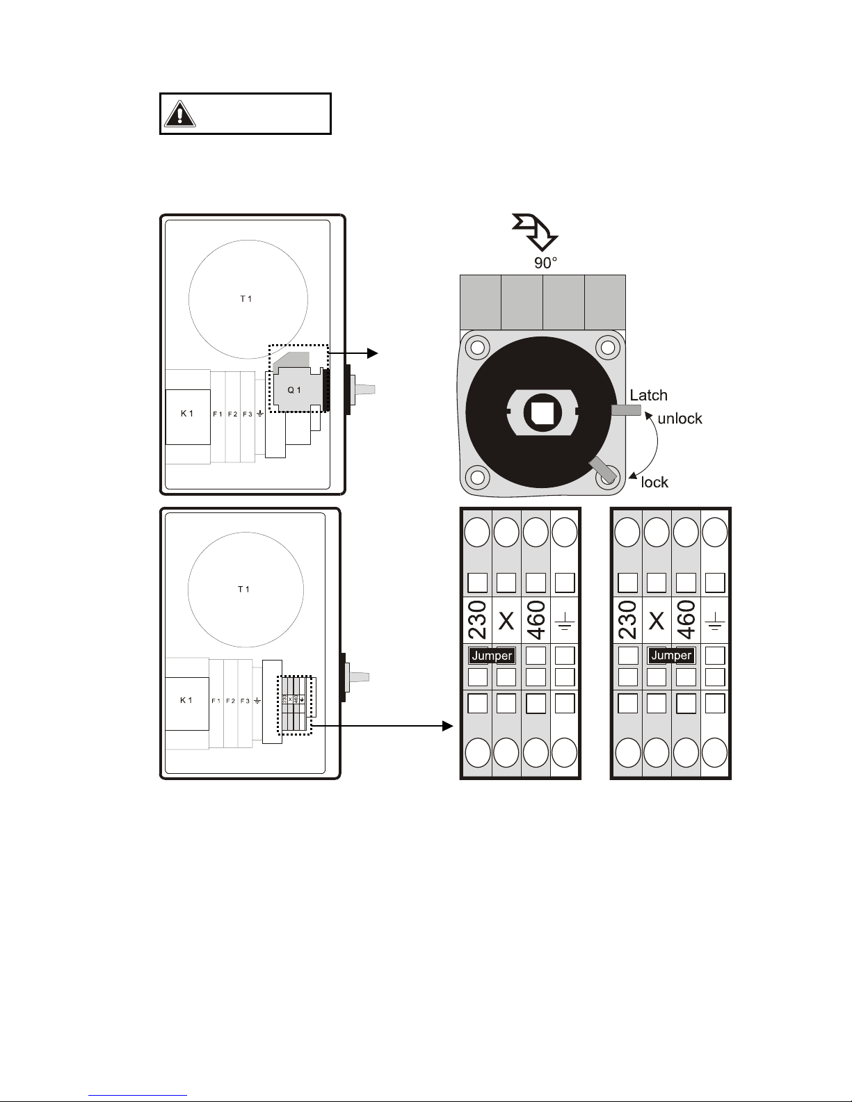
Jumper Setting
CAUTION
Prior to initial operation make sure the jumpers are set correctly. Non-compliance
may result in damage to motor and power supply unit !!!
Power Supply Unit
208/230 V 440/480 V
!!! Before opening power supply unit (MCB), ensure that it is disconnected from the Main
Power Supply (Wall Outlet) !!!
1) Open the power supply unit.
2) For ease of access, unlock main switch Q 1 (see illustration) and pull it off the square pin.
3) Verify the jumper setting corresponds to the line voltage.
4) If necessary, change the jumper setting using needle nose pliers.
5) Reinstall and lock the main switch.
6) Close the power supply unit.
CLM16 IOM.DOC 5/8/09
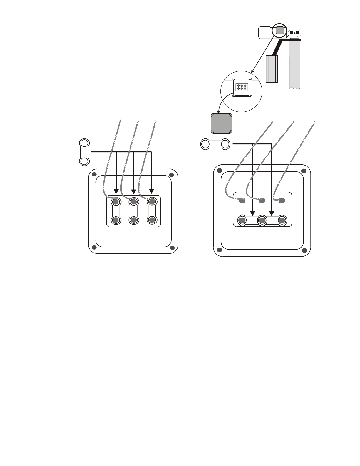
Motor
1) Remove the cover of motor junction box.
2) Verify the jumper setting corresponds to the
line voltage.
3) Reinstall cover of motor junction box.
Motor Cable Motor Cable
#1 #2 #3 #1 #2 #3
CLM16 IOM.DOC 5/8/09
For 208/230 V, three jumpers
must be set vertically. For 440/480 V, two jumpers must be set
horizontally in the lower row of terminals.
Final Checkout Procedure
Visually check the columns for shipping damage.
Run the lift through several full cycles.
Ensure that all controls are operating correctly.
Ensure that carriages are synchronized during the up and down movements.
Operational Test
Load the lift with a vehicle appropriate for this lift.
Run the lift through several full cycles.
Ensure that all controls are operating correctly.
Ensure that carriages are synchronized during the up and down movements.
Operation
CLM16 IOM.DOC 5/8/09
WARNING
In case of defects or malfunctions such as jerky lift movement or deformation of the
superstructure, support or lower the lift immediately !!!
Turn off and lock the main switch. Contact CHALLENGER LIFTS, INC.
Immediately !!!
Use lift only as indicated by the supplied instructions !!! Should you have further
questions, please contact CHALLENGER LIFTS, INC. !!!
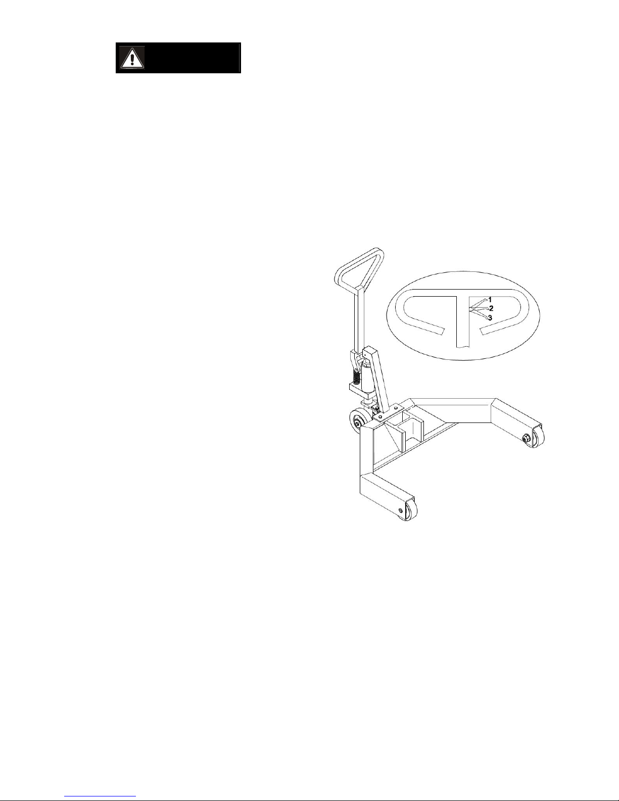
Moving the Columns
Hydraulic Dolly
Close hydraulic valve by putting valve lever in
position 3.
Pump with handle to raise the moving gear.
Move column to desired position.
To lower the moving gear, open the hydraulic
valve by putting the valve lever in position 1.
The column is ready for operation.
Position 2 is the neutral position.

Controls
Overview
P 1Power Supply Unit Main Switch
C Control Unit LED Display 2
Selector Button 3
Seven-Segment Display 4
"Raise" Button 5
"Lower" Button 6
Emergency Stop Button 7
CLM16 IOM.DOC 5/8/09

Installing the Power Supply Unit
Attach the power supply unit (P)
to the left side of the control
unit (C) to ensure easy access to
the main switch.
Main Switch
The main switch can also be used as an Emergency Stop switch. Turn to position 0.
Position 1: Lift is ready for operation.
Position 0: Lift is disconnected from mains supply. In this position
the switch can be padlocked.
NOTE:
After turning the unit ON, wait approx. 3 seconds until the control
has performed a self-test.
The lift is now in automatic mode. (A)
CLM16 IOM.DOC 5/8/09

Control Elements
LED Display
Indicates operating and error states.
Selector Button (on Control Unit)
Use this button to select between:
Automatic mode (A)
Single mode (S)
Group mode (G)
Seven-Segment Display (on Control Unit)
Indicates operating and error codes.
RAISE Button (on Control Unit)
Press and hold this button to raise the lift. Lift stops once button is
released or upward travel stop is reached.
LOWER Button (on Control Unit)
Press and hold this button to lower the lift. Lift stops once button is
released or downward travel stop is reached.
Emergency Stop Button (on Control Unit)
In case of emergency press this button to interrupt all lift functions
immediately.
Pull out the button to make the lift ready for operation again.
Make sure that prior cause of emergency has been resolved
before operating the lift again!
Overload Protection:
The lift control is equipped with an automatic overload protection device, shutting the lift off, in case
the rated load capacity is exceeded. In such case, the control only allows the lowering of the lift.
Always ensure that the operator observes the maximum rated load capacity.
Lift Positioning
Use the lift on a hard, level surface only, preferably concrete (Keep the lifted weight in mind!)
Apply the parking brake after positioning the vehicle.
Push the support forks completely under the wheels/lift points of the vehicle.
Attach the power supply unit (P) to the control unit (C) of the column closest to the main power
supply in your building.
Interconnect the columns using connecting cables (1) between input terminals (IN) and output
terminals (OUT). Connect a dummy plug or the cable remote control (2) to the output terminal of the
last column.
CLM16 IOM.DOC 5/8/09

NOTE:
Secure the connecting cable plugs using the safety clamps.
After connecting all columns plug MCB into wall outlet. Recheck all electrical connections.
Once the main switch is turned on, the lift is ready for operation.
1 PConnecting Cable Power Supply Unit
2 Dummy Plug Control Unit C
3 Main Plug (NOT included) Input Terminal IN
Output Terminal OUT
CLM16 IOM.DOC 5/8/09

Small Wheel Adapter Usage
CAUTION
Please read the following information
carefully before using your lifting system
!!!
Use the following tables to determine
which carriage combined with which Small
Wheel Adapter best fits the size tire on the
vehicle you intend to lift!!!
CLM16 IOM.DOC 5/8/09
This manual suits for next models
1
Table of contents
Popular Other manuals by other brands


Imagine
Imagine OPSS+OP+D Installation and operator's manual

wellbots
wellbots FREEFLY VR instruction manual

ReelCraft
ReelCraft 5635 OLPSW5 operating instructions

Safety 1st
Safety 1st GA048 user guide

Cineroid
Cineroid EVF4CSS user manual

JJM Boiler Works
JJM Boiler Works NBT Series Installation operation & maintenance