JABLOTRON ALARMS a.s.
Pod Skalkou 4567/33 46601 Jablonec n. Nisou
Czech Republic www.jablotron.com
||
|
The JA-112E Bus access module with RFID
The JA-112E Bus access module with RFID 1 MLU51310
The access module is a component of the JABLOTRON JA-100 system.
Its modular architecture enables users to create a combination whose size of
installation perfectly meets their needs. The device should be installed by a
trained technician with a valid certificate issued by authorized distributor.
The module comprises first control segment (1) and an RFID card / tag
reader (3). The JA-192E segments can be used to extend the
JA-112E unit by the required number of segments (the max. allowed amount
is 20 on one unit).
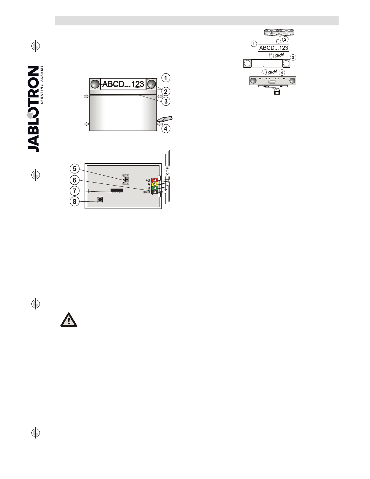
Figure 1: 1 – control segment; 2 – segment buttons; 3 – backlit activation
button with RFID reader; 4 – tabs for module opening
Figure 2: 5 – connector for control segments; 6 – BUS terminals,
7 – production code; 8 – tamper contact
Installation
1. Press the four tabs (4) on the sides one by one and release the module
from the plastic base.
2. When installing more control segments, first remove the socket cover on
the 1st segment.
3. Remove the transparent plastic cover from the segments (by levering
on both sides of the segment near the buttons).
4. Always connect the segment wires to the connector of the previous
segment and click them into each other (we recommend coiling the wires
by turning the segment by 360° – this will prevent any possible damage to
the wires between the plastic parts). Use this method to install all the
required segments. Finally push the socket cover in.
5. Push the cable through the plastic base and attach the base to the
selected place together with the segments using screws. If more
segments are required fix them onto the wall using screws as well.
6. Connect the BUS cable to the bus terminals (6).
When connecting the module to the bus,
always switch the power off.
7. Connect the segment wires to the internal connector of the module (5).
8. Insert the RFID module into the base.
9. Proceed according to the control panel installation manual. Basic
procedure:
a. When the device is switched on, the yellow backlit activation button
(3) starts flashing repeatedly to indicate that the module has not
been enrolled into the system.
b. Go to the F-Link software, select the required position in the
Devices window and launch the enrollment mode by clicking on
the Enroll option.
c. Press the backlit activation button (3) – the access module
is thus enrolled and the yellow LED indicator goes off.
10. When you have completed the installation, insert descriptive labels onto
the segment transparent covers and close them, see figure 3. Label
printing is a part of the F-Link software (Devices window, at the module
position – Internal settings).
Notes:
The module can also be enrolled to the system by entering its production
code (7) in the F-Link software or using a bar code scanner. All numbers
stated under the bar code shall be entered (1400-00-0000-0001).
To comply with the EN 50131-3 norm it is necessary to fix the cover tabs
(4) by the screws from the accessories. In picture no 1 the cover tabs are
displayed and marked by the arrows.
Figure 3: Insertion of a label into a control segment
Unit modifications
If you need to change the unit’s individual segments, it is possible to
separate them by levering the corresponding separating gaps from one side
(sideways from the buttons). Make sure the system BUS is disconnected.
Setting the properties
Go to the Devices window in the F-Link software. When you are at the
module position, use the Internal settings option. The particular unit is
displayed and it is possible to set its properties. Internal settings is separated
into 2 basic tabs: Segments and Settings.
It is possible to set the required functions for individual segments (control
of sections, section status signalling, alarm triggering, PG output control, PG
output status signalling, etc.). More details are available in the F-Link
software.
3rd optional setting tab Common segment – settings and function
description
Acommon segment (up to 2 of them allowed on one module unit)
simulates the simultaneous pressing of several segments which are placed
on this module and which control sections. In the Segments tab and select
the specific segment function called Common segment A (B). Then in the
new tab Common segment select the segments which will be operated en
bloc.
Note: A module has to be equipped with a minimum of 3 segments otherwise
this function cannot be used.
The selected sections will all be set / unset after pressing a button on the
common segment.
If the states of the segments which are operated by the common segment
are mixed, then only the segments that need changing will be set / unset.
If partial setting is enabled for some segments, then the common segment
respects this: 1st press = partially setting, 2nd press = full setting. It is not
suitable to combine a common segment with a common section
The indication of the common segment is: all segments unset = green,
some set (partially set) = yellow, all sections fully set = red.
In the Settings tab you can set all other module functions like acoustic
signalling, backlight intensity, RFID reader mode, optical and acoustic
indication, etc. Details related to settings can be found in the installation
manual of the control panel and of course in the tooltips displayed by the
F-Link software.
Optical indication
Activation button – indicates the system status. No light – sleep mode,
green light – everything OK, green flashes – authorisation performed, red
flashes – alarm, yellow light – fault, yellow flashes – not enrolled to the
system, yellow double flash – Service mode.
Note: The activation button doesn´t indicate module tamper activation in
Service mode.
Segments – don´t indicate a thing when Service mode is entered or when
the segment has the function None. The optical indication of a PG segment
can be inverted.
Module can be preset to the following 6 indication levels:
1. Indicates permanently – BUS modules indicate permanently only if
an external power supply is connected. Without an external power
supply it indicates the same as option 2. When the mains is restored
module again indicates permanently.
2. Section / PG status change on keypad – the module indicates
when the section / PG status has been changed. The status change
is indicated on the specific segment. Entrance delays and alarms are
indicated by the whole module.
3. Section / PG status change on segment – the module indicates
when a section / PG output status has been changed. A segment
status change, an entrance delay and an alarm is indicated on a
specific segment.
4. Segment status change on keypad – The module indicates when
the status of a segment has been changed (setting, unsetting, PG
ON, PG OFF). The change of the status is indicated only on the
specific segment.
5. Entrance delays / alarms on segment –themoduleindicates
entrance delays and alarms on a specific segment.