Challenger EPS0412 User manual
Imported exclusively by Pacific Hoists Pty. Ltd. & Pacific Hoists Ltd.
In support of cancer charities in Australia & New Zealand
INSTRUCTION
MANUAL
ELECTRIC LIFTER
TROLLEY

www.jbstools.com
2WWW.CHALLENGERHOISTS.COM.AU

www.jbstools.com 33
INTRODUCTION
Thank you for purchasing your new Challenger Electric Lifter Trolley. The Challenger Electric Lifter
Trolley is made of high quality steel which is designed to be durable, reliable and easy-to-use. Also
choosing the Challenger brand directly supports cancer charities in Australia and New Zealand.
It is important that this manual be kept in a safe place where any operator of the Challenger
Electric Lifter Trolley can refer to it and understand the operating principles of this device. All
users of this Challenger Electric Lifter Trolley should read this manual in full and understand the
safe operating principles of the device.
IMPORTANT
PLEASE READ THIS OPERATION MANUAL BEFORE USING THIS PRODUCT. THIS MANUAL CONTAINS
IMPORTANT INFORMATION REGARDING SAFETY, OPERATION, INSTALLATION & MAINTENANCE.
ALWAYS OPERATE, INSPECT AND MAINTAIN THIS PRODUCT IN ACCORDANCE WITH
INSTRUCTIONS IN THIS MANUAL,
Model EPS0412 EPS0415 EPS0417
Stock code CES120 CES150 CES170
Rated capacity (kg) 400
Max. height (A) x width (B) (mm) 1425 x 600 1725 x 600 1925 x 600
Max. platform height (C) (mm) 1200 1500 1700
Min. platform height (D) (mm) 85
Platform length (E) x width (F) (mm) 650 x 576
Lifting height (mm) 1115 1415 1615
Lifting speed with load (mm/sec) 0 - 80
Lowering speed with load (mm/sec) 0 - 115
Storage battery DC12V - 60AH
Motor DC12V - 700W
Max. trolley length (G) (mm) 1100
Net weight (kg) 118 126 130
SPECIFICATIONS

www.jbstools.com
4WWW.CHALLENGERHOISTS.COM.AU
SPECIFICATIONS

www.jbstools.com 55
GENERAL PRECAUTIONS
■The operator should read the instructions before using this electric lifter trolley to avoid any
injuries
■This electric lifter trolley is used to lift and lower loads within it’s rated capactiy
■The electric lifter trolley should only be operated by persons who are authorised to do so
■Examine the electric lifter trolley before use
■Do not overload the electric lifter trolley
■Pay attention to and ensure all loads are secured correctly
■If the load moves when the electric lifter trolley is in use, brake immediately
■Distribute the weight of the load across both forks evenly, do not use a single fork only
■Do not load the electric lifter trolley with imbalanced or unstable loads
■Ensure correct maintenance of the electric lifter trolley according to the service instructions
■Do not modify or repair the electric lifter trolley without first consulting the distributor
■Check the battery before use and recharge in case of low power in a dry, well ventilated area
■Lower the forks once loading has been completed to avoid any injuries
■When servicing the electric lifter trolley ensure all loads are removed and use the safety
stopper to prevent the platform from lowering
■This electric lifter trolley is not designed to be weather resistant. When not in use store in
dry conditions and ensure the forks are lowered

www.jbstools.com
6WWW.CHALLENGERHOISTS.COM.AU
MAINTENANCE
REGULAR INSPECTION OF YOUR CHALLENGER ELECTRIC LIFTER TROLLEY WILL HAVE A
TWOFOLD RESULT BY ENSURING THE UNIT IS SUITABLE FOR SAFE OPERATION AND WILL
ASSIST WITH EXTENDING THE OPERATING LIFE OF THE UNIT. THE FOLLOWING INSPECTION
SHOULD BE PERFORMED BOTH PRIOR TO, AND AFTER, EVERY USE:
■Check for any bending or cracking on the electric lifter trolley
■Check for any oil leakage from the cylinder
■Check the subside of the electric lifter trolley while the platform is lifted to the highest position
■Check that the wheel movement is smooth
■Check the function of the brake
■Check all the bolts and nuts are tightened firmly
■Check the voltage of the battery indicator
■Check the hydraulic oil and lubrication periodically
■Check the oil mass every month
■Ensure equipment is serviced and maintained
CAUTION: DO NOT use the electric lifter trolley if any malfunction or fault is found
WARNING
■Do not place hands or feet under the platform
■Do not move the electric lifter trolley when the forks are lifting
■Do not move the electric lifter trolley unless the forks are lowered to a safe position
■Do not place feet in front of the swivel wheel, this may cause harm as the load is being
lowered
■Do not overload the electric lifter trolley
■Do not use the electric lifter trolley on uneven surfaces
■Never use the electric lifter trolley for the trasportation or movement of personel

www.jbstools.com 77
OPERATING INSTRUCTIONS
■To brake, press the brake pedal located on the left side of the swivel caster
■To release the brake, lift the brake pedal
■To lift the forks, turn the emergency stop button on the control panel clockwise and operate
the up button in the centre of the control panel
■To immediately stop the forks rising or lowering, push the emergency stop button
■To lower the forks, press the down button on the control panel
■To stop the forks lowering, release the down button on the control panel
■Do not overload the electric lifter trolley, ensure the load is within the rated capacity
■Do not side or end load. The load must be distributed on at least 80% of the platform area
CHARGING THE BATTERY
■Charge the battery when the voltage of the storage battery is low
■The electric lifter trolley uses a maintenance free storage battery, which does not involve
adding water
■Charge the battery in a dry, well ventilated area away from sparks and ignition sources
■To charge the battery, pull out the charger plug on the left side of the electric lifter trolley and
insert into a socket with the specified voltage. Remove when the full charge indicator light on
the panel goes on
■During charging, the voltage display on the indicating gauge should be lower than 16V
■Do not use the electric lifter trolley during charging

www.jbstools.com www.jbstools.com
8WWW.CHALLENGERHOISTS.COM.AU
CONTROL PANEL
■Press the emergency button, to disconnect the power supply of the pump station motor
■Turn the emergency button clockwise to connect the motor
■When the voltmeter is below 10V, the storage battery must be charged
■The up/ down buttons are used to raise or lower the forks
EMERGENCY BUTTON UP/ DOWN BUTTONS VOLTMETER

www.jbstools.com www.jbstools.com www.jbstools.com
99
TROUBLE SHOOTING
No. Fault Cause Countermeasures
1The forks cannot
reach the max. height
• Low hydraulic oil level • Inject hydraulic oil
2The forks cannot be
raised
• No hydraulic oil
• Hydraulic oil is impure
• Check hydraulic oil
• Replace the hydraulic oil
3Pump station motor
cannot run
• Emergency button is not
switched on
• Low voltage of the storage
battery
• Wiring terminal of the power
line is loose
• Motor contactor is damaged
• Turn the emergency button
clockwise
• Charge the battery
• Fasten the wiring terminal
• Replace the parts
• Contact you distributor
4The forks will not
lower
• Uneven centre of gravity
of goods or overloading
causes deformation of the
large piston rod or the oil
tank body
• The forks are rusted
and hard to move due to
long-term exposure to air
when the platform stays in
the higher position for an
extended period of time
• The release valve of the
hydraulic pump station is
worn or damaged and thus
cannot be opened
• Replace the large piston
rod or the oil tank body
• Lower the forks to the
lowest position when not
using the crane and make
sure to lubricate the piston
rods
• Replace the release valve
of the pump station
• Contact you distributor
5Oil leakage • Sealing parts are aged or
damaged
• Some parts are broken
• Replace the parts
• Replace the parts
• Contact you distributor
6Forks lower itself • The relief valve is unable to
be shut tightly due to impure
hydraulic oil
• Sealing parts are aged or
damaged
• Release valve is damaged
• Replace the hydraulic oil
• Replace the parts
• Replace the parts
• Contact you distributor
7Storage battery
cannot be charged
• Storage battery is damaged
• Charging plug is loose
• Replace the parts
• Check connections
www.jbstools.com www.jbstools.com 1010
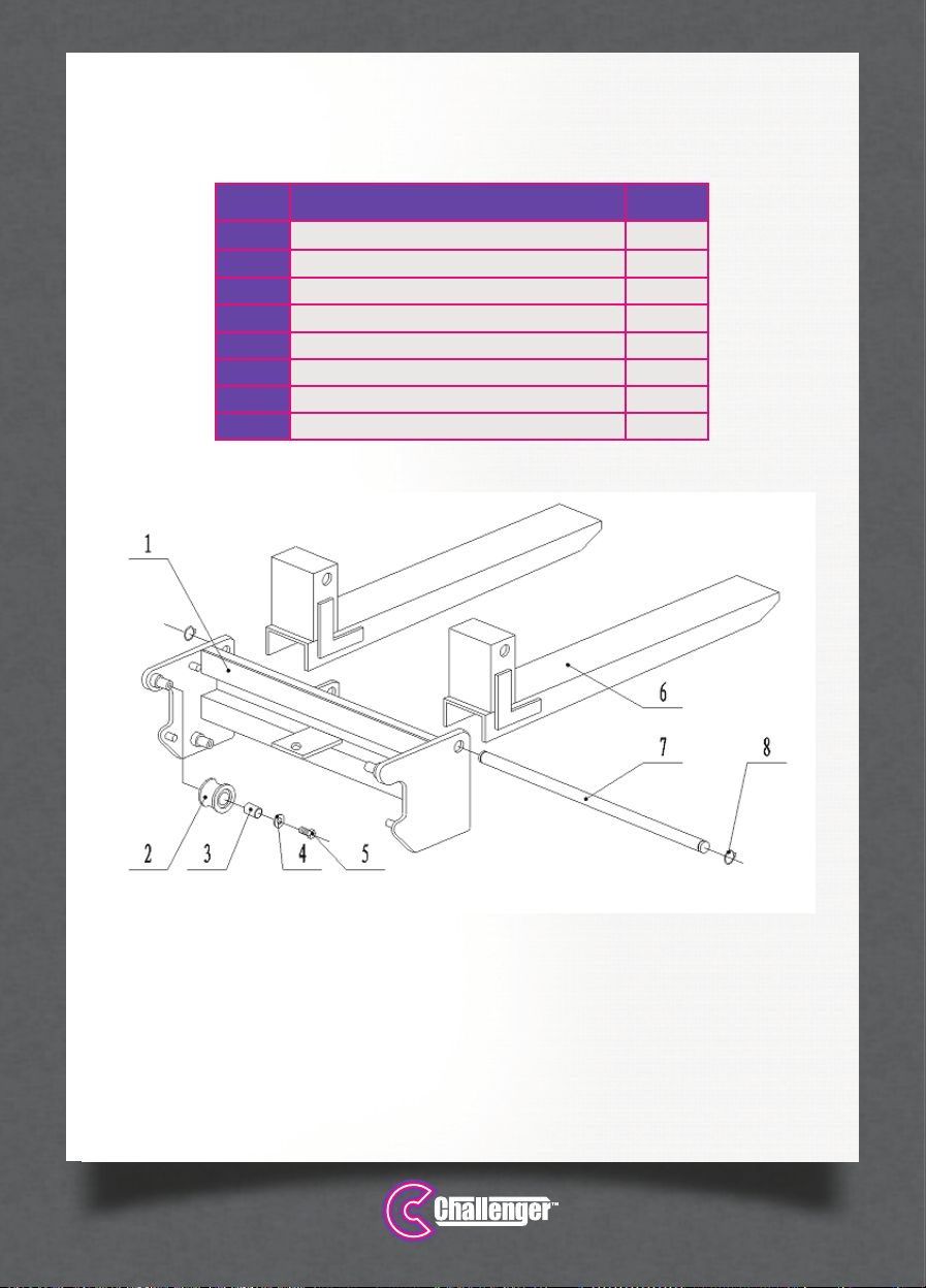
SPARE PARTS
No. Description Qty.
1Bracket 1
2Roller 4
3Composite sleeve 4
4Ultra big washer 4
5Full thread hexagon headed bolt M6X16 4
6Tyne 2
7Long axis 1
8Spring washer for shaft 2

www.jbstools.com 1111
SPARE PARTS
No. Description Qty.
1Handle 1
2Split washer 2
3Chain wheel 1
4Composite sleeve 2
5Chain wheel cap 1
6Chain wheel cap 1
7Chain wheel shaft 1
8Hexagon socket set screws with flat point 1
9Chain 1
10 Chain joint 2
11 Chain tie rod 2
12 Hexagon nut 6
13 Non-metal hexagon lock nut 2
14 Full thread hexagon headed bolt 4
15 Spring washer 4
16 Hexagon nut 4
17 Full thread hexagon headed bolt 4
18 Flat washer 8
19 Spring washer 4
20 Split washer 4
21 Front wheel axel 2
22 Gasket 4
23 Bearing 4
24 Front rollers 2
25 Chasis 1
26 Steering wheel (with brake) 2
27 Cap nut 2
28 Internal tooth lock washer 2

www.jbstools.com
12 WWW.CHALLENGERHOISTS.COM.AU
SPARE PARTS

www.jbstools.com 1313
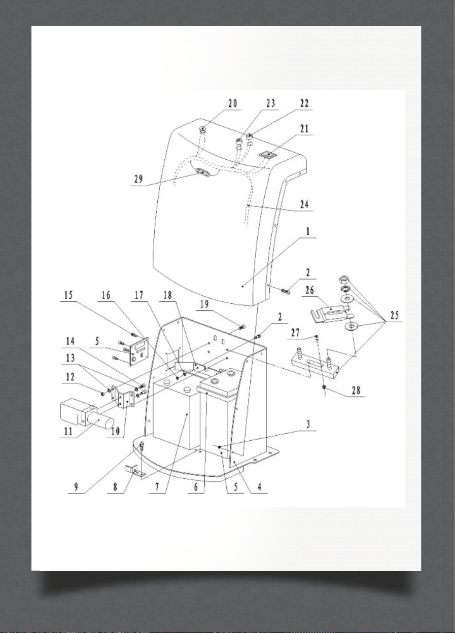
SPARE PARTS
No. Description Qty.
1Electric appliance cap 1
2Cross recess head screw M6X16 11
3Embedded nut 8
4Electric cabinet 1
5Charger 12V/10A 1
6Anchor ear 1
7Storage battery 1
8Fixture 1
9Hexagonal socket head cap screw 2
10 Oil pump installation board 1
11 Pump station 1
12 Hexagon nut 4
13 Spring washer 6
14 Hexagonal socket head cap 2
15 Cross recess head screw 4
16 Hexagon nut 3
17 Flat washer 6
18 Conductor board 1
19 Full thread hexagon headed bolt 4
20 Emergency stop button 1
21 Voltmeter 1
22 Up switch 1
23 Down switch 1
24 Control wiring harness 1
25 Fuse holder 1
26 Fuse 1
27 Screw 2
28 Nut 2
29 Fuse 1
www.jbstools.com
14 WWW.CHALLENGERHOISTS.COM.AU
SPARE PARTS

www.jbstools.com 1515
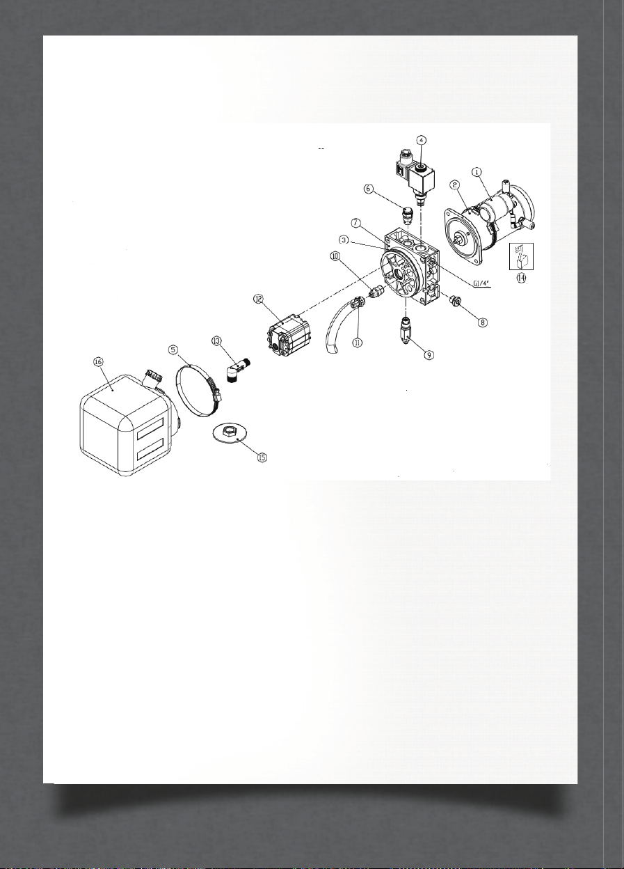
SPARE PARTS
No. Description Qty.
1Start switch 1
2Motor 1
3O-ring 1
4Solenoid pilot actuated valve 1
5Clamp 1
6Stop valve 1
7Central valve body 1
8Screw 1
9Safety valve 1
10 Flow control valve 1
11 Fuel return tube 1
12 Gear pump 1
13 Fuel suction tube 1
14 Carbon brush 1
15 Filter 1
16 Fuel tank 1
www.jbstools.com
16 WWW.CHALLENGERHOISTS.COM.AU
SPARE PARTS

www.jbstools.com 1717
SPARE PARTS
No. Description Qty.
1Piston rod 1
2Steel wire washer for shaft 1
3Piston 1
4Spring washer for shaft 1
5Dustproof ring 1
6Y sealing ring for shaft 1
7End cover 1
8O-ring 1
9Oil tank body 1
10 Composite gasket 1
11 Oil release screw plug 1
12 Composite gasket 2
13 Long joint 1
14 Safety valve 1
15 Joint body 1
16 Single 90° high-pressure oil pipe 1
17 Right angle adjustable joint 1

www.jbstools.com
18 WWW.CHALLENGERHOISTS.COM.AU
SPARE PARTS

www.jbstools.com 1919
INITIAL SERVICE DATE: SERIAL NO:
DATE NOTES AUTH SIGNATURE
Imported exclusively by Pacific Hoists Pty. Ltd. and Pacific Hoists Ltd.
For further information in relation to this product,
please contact the branch where the product was purchased.
HEAD OFFICE
24 Foundry Road, Seven Hills NSW 2147
National Sales & Service P: 02 8825 6900
www.challengerhoists.com.au
INSPECTION LOG
Thank you for choosing the Challenger brand. Not only are you
choosing a quality and reliable brand but you are also helping
to support cancer charities in Australia & New Zealand.

This manual suits for next models
2
Table of contents
Popular Forklift manuals by other brands


NIFTYLIFT
NIFTYLIFT SD50 Operation?and safety

EP Equipment
EP Equipment IMOW ICE251 Operation manual

Dieci
Dieci Apollo 25.6 Operation and maintenance manual

Xtreme Manufacturing
Xtreme Manufacturing XRM945 Operation & safety manual

Daewoo
Daewoo D20S-2 Specifications Systems Operation Testing & Adjusting Disassembly & Assembly

OTTO MOTORS
OTTO MOTORS Lifter V1 Operation and maintenance manual


