Chalmit Curie Elite ATEX Manual
I-CUEE-03.doc Issue 09 28/04/2021 1
IOM – CURIE ELITE - ZONE 1 RECESSED
Curie Elite
IP65 Recessed LED Luminaires
ATEX, IECEx and UKEX
INSTALLATION, OPERATION AND MAINTENANCE INSTRUCTIONS
Important: Please read these instructions carefully before installing or maintaining this equipment.
Good electrical practices should be followed at all times and this data should be used
as a guide only.
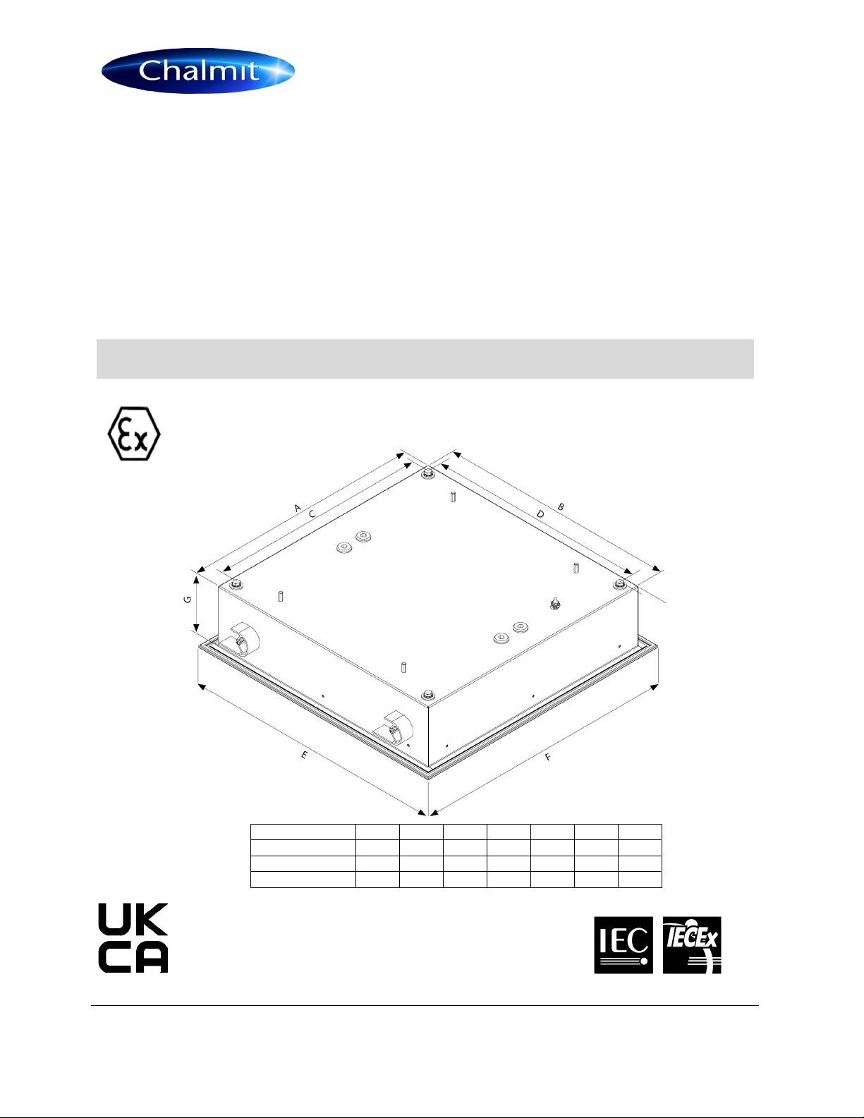
Luminaire Dimensions
A
BCDEFG
/MST 547 547 500 500 599 599 135
/MET 572 572 500 500 624 624 135
STANDARD 572 572 500 500 644 644 135
I-CUEE-03.doc Issue 08 28/04/2021 2
IOM – CURIE ELITE - ZONE 1 RECESSED
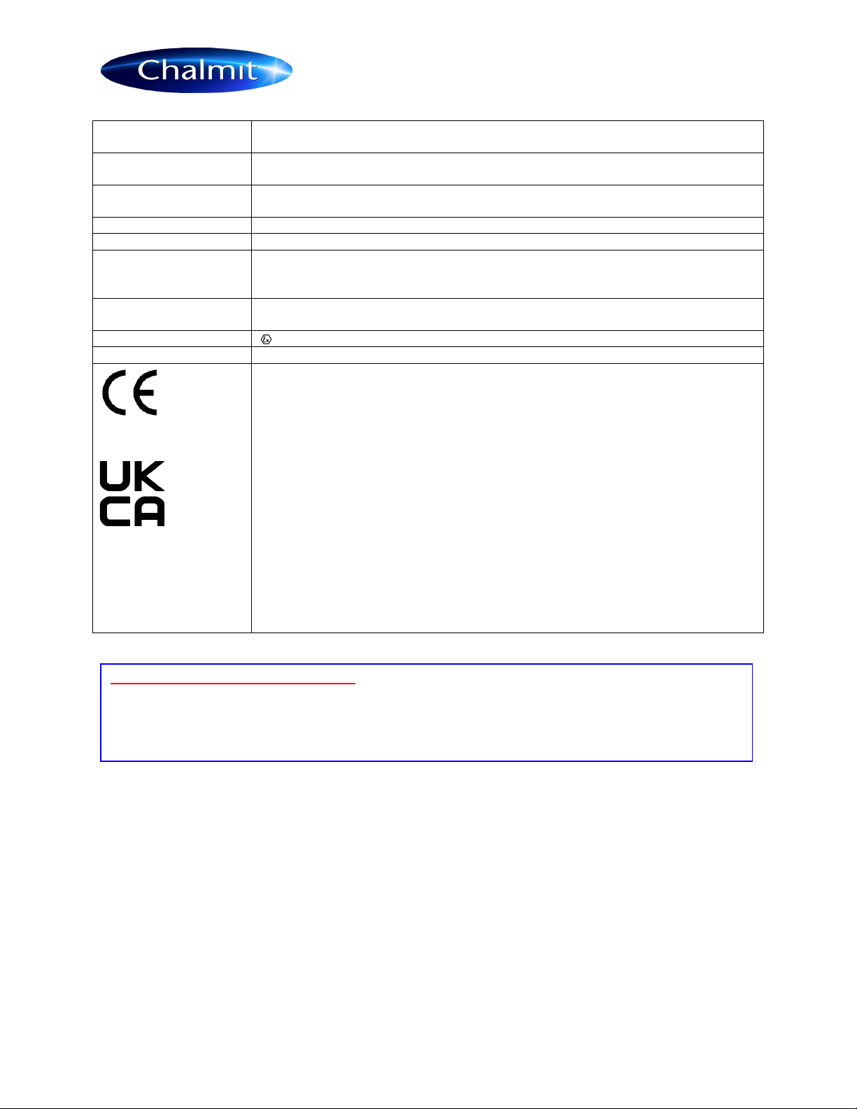
0.0 Specification
Type of Protection Ex eb mb op is qb Increased safety, Encapsulation, optical radiation, powder filling.
(With isolating switch: Ex db eb mb op is qb Flameproof is added)
Protection Standards (IEC) EN 60079-0, (IEC) EN 60079-1, (IEC) EN 60079-5, (IEC) EN 60079-7,
(IEC) EN 60079-18, (IEC) EN 60079-28, (IEC) EN 60079-31
Area Classification Zone 1 and 2 areas to EN 60079-10-1, Zone 21 and 22 areas to EN 60079-10-2.
Installation EN 60079-14
Certificate IECEx Certificate of Conformity IECEx CML 16.0108X
EU Type Examination Certificate CML 16ATEX3335X
UK Type Examination Certificate CML 21UKEX1499X
Equipment Coding Ex eb mb op is qb IIC T4 Gb or Ex db eb mb op is qb IIC T4 Gb
Ex tb IIIC T95°C Db IP6X (-20 to +45°C Insulated, +55°C Uninsulated)
ATEX/UKEXCoding II 2 G D
Ingress Protection IP65 to EN 60529
The CE marking of this product applies to "The Electrical Equipment (Safety) Directive”,
The Electromagnetic Compatibility Directive", the “Waste Electrical and Electronic Equipment
Directive” and the "Equipment and Protective Systems intended for use in Explosive
Atmospheres Directive". [2014/35/EU, 2014/30/EU, 2012/19/EU and 2014/34/EU respectively].
The UKCA marking of this product applies to "The Electrical Equipment (Safety) Regulations
2016", "The Electromagnetic Compatibility Regulations 2016", the “Waste Electrical and
Electronic Equipment Regulations 2012” and the "Equipment and Protective Systems intended
for use in Explosive Atmospheres Regulations 2016
The Equipment is declared to meet the provisions of the ATEX directive (2014/34/EU)
by reason of the Type Examination/EU Type Examination and meets the UK statutory
requirements Sl 2016 No.1107 and compliance with the Essential Health and Safety
Requirements.
M Poutney Technical Manager
Luminaire is supplied with Battery disconnected, just prior to switching power on
connect battery.
1.0 Introduction – Curie Elite
The Curie Elite LED series is available as non-modular and modular recessed clean area luminaire for use with
Ex mb LED strips with the option of an internal battery back up for emergency use. The non-modular is suitable
for cut or prepared aperture ceilings. The modular is suitable for Exposed T and Spring T modular grid ceilings.
The Curie Elite models have Ex q control gear and micro-processor controlled emergency functions. Normal
operation is mains supply with all lamps on, switching to reduced output on battery back up and having local
switching of the mains lamps, the emergency function only being energised on mains failure.
The luminaries are available in for Modular and Non Modular Ceilings.
Refer to the current catalogue for information on product references.
SPECIAL CONDITIONS FOR SAFE USE
- Connections to the terminals must not be made outside the range of -10°C to +80°C.
- Where used, all terminal screws, used and unused, shall be tightened down to between 1.2 Nm and
2Nm.
- The Ex q driver is sealed and must not be opened without returning it to the manufacturer.

I-CUEE-03.doc Issue 08 28/04/2021 3
IOM – CURIE ELITE - ZONE 1 RECESSED
B15 SOLAS The luminaire can be installed to interface with fire resistant ceiling systems to maintain a B15
SOLAS fire rating; the integrity of the ceiling and insulation must be maintained using suitable insulation
materials. The ceiling/fitting and insulation should be continuous (without any gaps), care must be taken to
maintain this classification.
2.0 Electrical Supplies
Nominal Lamp Power and Supply Current
Lamps 03L - 6x 400mm LED Strip
Voltage range AC 110-130V or 220
–
254V
Frequency range Hz 47-63Hz
Power Watts 220-254V 64W EM, 61W NON EM
Current Amps 220-254V 0.30
–
0.26A EM 0.29
–
0.25A NON EM
Power Watts 110-130V 64W EM, 61W NON EM
Current Amps 110-130V 0.61 - 0.51A EM 0.59
–
0.50A NON EM
Batteries 6V 7Ah NiCd
Emergency Duration 90 minutes or 3 hours depending on model specified
Power Factor >0.98 Power is constant over voltage range.
Over voltage 400V ac for 1 min and EN 61000-4-5 > 4kV
Through Wiring The through current rating is 16A. 4mm² terminals are standard (6mm² wiring can be
used in the terminals in accordance with the luminaire certificate).
Tamb Storage -40°C to +80°C
Storage Luminaires and control gear boxes are to be stored in cool dry conditions
preventing ingress of moisture and condensation.
Battery packs in storage should be cycled charged/discharged/charged every 9
months, as per instructions in section 5.6.
Always disconnect battery plug and socket for storage.
Any specific instructions concerning emergency luminaires must be complied
with.
(Warning: Battery packs not cycled and stored for a year may not be
recoverable)
Fuse and MCB Ratings It is recommended that for selection of MCBs users should consult the MCB
manufacturer as this unit contains electronic control gear. MCB ratings can vary
depending on the manufacturer and type and the size of the installation. The electronic
control gear has nominal values of inrush current of 35A for 70µs on 230V and 70A for
70µs on 110V.

I-CUEE-03.doc Issue 08 28/04/2021 4
IOM – CURIE ELITE - ZONE 1 RECESSED
TYPICAL WIRING FOR EMERGENCY VERSION
3.1 General
These instructions should be read fully and carefully before attempting to install the luminaire.
For details of servicing operations, opening etc. see section 6.
Copies of these instructions should be held in a safe place for future reference. It is the responsibility of the
installer to ensure that the apparatus selected is fit for its intended purpose and that the installation, operation
and maintenance of the apparatus complies with applicable regulations, standards or codes of practice.
There are no health hazards associated with this product whilst in normal use, however, care should be
exercised during the following operations.
Installation should be carried out in accordance with EN 60079-14 or with a local hazardous area code of
practice, whichever is appropriate. Any specific installation instructions must be referred to. In the UK the
requirements of the Health and Safety at Work Act must be met and electrical work associated with this product
must be in accordance with the “Manual Handling Operations Regulations” and “Electricity at Works Regulations
1989”. Disposal instructions should be complied with.
The luminaires should be considered Class 1 to EN 60598 and effectively earthed.
The polycarbonate diffuser, if fitted, presents a potential source of ignition by electrostatic electricity. The
diffuser should only be cleaned using a damp cloth. The luminaire should not be mounted very near to any
probable location of fast moving stream of dry air, steam etc. which could generate a propagating brush static
discharge.
To avoid applying static charge or scratching the diffuser:
Never handle the polycarbonate diffuser with bare hands, use lint free gloves and carry using the frame.
Never polish the diffuser with a dry cloth.
If, due to site conditions the diffusers become dirty, they should be cleaned with an airgun. If smears are
difficult to remove use a bucket of lukewarm soapy water and allow to dry naturally with the frame standing
vertically. Do not polish dry as this will reapply static charge. Use only the recommended detergent at the
stated concentration.
Certification details on the rating plate must be verified against the application requirements before installation.
The presence of certain chemicals in the explosive atmosphere may cause a chemical reaction with non-metallic
materials such as the polycarbonate diffuser and silicone/EPDM gaskets that could have detrimental effect on
their performance. Chemical compatibility is highly dependent on concentration, temperature, humidity and other
environmental conditions. The end use will assume responsibility for evaluation of gaseous or direct contact
compatibility at their site prior to product installation. If in doubt please contact Chalmit sales.
The luminaire is tested to EN 60598-1.

I-CUEE-03.doc Issue 08 28/04/2021 5
IOM – CURIE ELITE - ZONE 1 RECESSED
The information in this leaflet is correct at the time of publication. The company reserves the right to make
specification changes as required without notice.
3.1.1 Use in Combustible Dust Atmospheres
Where the equipment is used in combustible dust atmospheres, reference must be made to the selection and
installation standards in order that the equipment is used correctly. In particular this applies to the de-rating of
surface temperature for use where dust clouds may be present.
Refer to EN60079-10-2 & EN 60079-14 for additional details of selection, installation and maintenance
3.1.2 Hybrid Mixtures – Gas plus Dust.
Where Hybrid mixtures exist as defined in EN1127 as a potentially explosive atmosphere, consideration should
be given to verifying that the maximum surface temperature of the luminaire is below the ignition temperature of
the hybrid mixture.
3.2 Tools
12mm , 4mm and 3mm flat blade screwdriver. Socket head torque screwdriver. Suitable spanners for installing
cable glands.
Pliers, knife, wire strippers/cutters.
3.3 Electrical Supplies
Luminaires are supplied with control gear suitable for the following rated supplies
Emergency 110-130V and 220-254V ac
Non-emergency 110-130V and 220-254V ac
The safety limit for surface temperature (T rating) is +/-10% on the rated voltage. Equipment should not be
operated continuously at more than +10/-10% of the rated voltage of the control gear. The power factor
correction gives a minimum of 0.95 lagging. The lamp supply is regulated therefore the change in light output
over the supply range is substantially unchanged.
3.4 Mounting
Luminaires should be installed where access for maintenance is practical and in accordance with lighting design
information. Refer to the note in 3.1 concerning electrostatic charge.
Non-modular types: Prior to mounting remove front cover by undoing screws, releasing the safety chains and
removing the gear tray; put front cover into a safe and clean place so as not to accumulate dust. Remove bag
containing disposable caps from inside the luminaire. Ensure suspension brackets are flush with sides prior to
positioning into the ceiling, ensuring that no cable is trapped. Position luminaire until the front flange meets the
ceiling face.
Support into position from below. The ceiling suspension is activated from in front of the ceiling using a socket
head torque screwdriver. Rotate the suspension bolt heads anticlockwise and the suspension arm will then
activate and swing outwards, it then travels down onto the ceiling batten. Once contact has been made,
gradually tighten until the recommended torque of 1Nm has been reached. Confirm torque of bolts upon
completion of this operation. When the assembly is complete fit the plastic caps.
Modular Types: Remove cover and gear tray and put into a safe place. Remove ceiling suspension cams from
the sides of the luminaire.
Exposed T ceilings: Remove adjacent ceiling tiles from the sides of the luminaire, push the luminaire into the
ceiling aperture and whilst supporting, fit two of the cams on diagonally opposite corners and screw in place. The
luminaire is now temporarily supported and remaining cams may be now fitted. The cam brackets should now be
gradually rotated clockwise until the compression gasket is over half compressed. This should be done in
sequence so as not to buckle the ceiling or damage the fitting by over stressing at any point.
Spring T ceilings: Remove the adjacent tiles from the sides where the ceiling suspension mates. Push the body
of the luminaire into the ceiling aperture ensuring the body sits centrally in the ceiling structure. Fit two of the
cams on diagonally opposite corners and screw in place. The luminaire is now temporarily supported and
remaining cams may be now fitted. The cam brackets should now be gradually rotated clockwise until the front
cover is flush/level with adjacent tiles. This should be done in sequence so as not to buckle the ceiling or
damage the fitting by over stressing at any point.

I-CUEE-03.doc Issue 08 28/04/2021 6
IOM – CURIE ELITE - ZONE 1 RECESSED
Suspension mount holes: If using the 4 additional suspension mount holes on the rear of the fitting, please
ensure the sealing washers are fitted and torqued to a value of 2.5Nm.
3.5 Cabling and Cable Glands
The temperature conditions at the supply cable entry point are such that 70ºC (ordinary PVC) cable can be used.
The installer and user must take responsibility for the selection of cables, cable glands and seals.
The product is certified for ATEX, IECEx and UKEX and to comply with the certification for installation cable glands and
sealing plugs must be ATEX, IECEx or UKEX certified depending on site requirements.
The cable and gland assembly when installed must maintain a minimum IP65 rating.
Where the cable is not reliably clamped externally to the apparatus the cable gland must clamp the cable
against a pull in Newtons of 20 x the cable OD in mm.
Four entries suitable for M20 are provided. Three entries are fitted with suitably approved blanking plugs, the
fourth entry with a transit plug. Other sizes are available on request.
3.6 Electrical Connections and Testing
If work is to be done on any luminaire already connected to the electrical system, the luminaire must be isolated
from the system. Access for the cabling is via removal of front cover and lamp tray. The front cover is secured
using 6/10 off M6 captive screws, care to be taken as there is no suspension on this, and lampholder tray is
secured by M5 screws and keyhole slots, with chain suspension allowing the tray to swing down, giving access
to terminal blocks. Install the conductors in the appropriate terminals. Take care not to cut the conductor
insulation excessively, 1mm of bare conductor outside the terminal throat is a maximum. Before re-fitting
lampholder tray and front cover, the cores/cable should be neatly tucked away and a final check made on correct
connections.
Luminaires are supplied suitable for looping and through wiring.
The through current rating is 16A. 4mm² terminals are standard (6mm² wiring can be used in the terminals as
per the certificate).
Screw type or screw-less “cage clamp” terminals are fitted in the range of luminaires. Mains terminal blocks are
marked L N Earth.
Mains terminal blocks on the emergency luminaires are marked Lc Ls N Earth.
Luminaires can also be supplied with three phase wiring to special order. The marking is L1 L2 L3 L s N Earth
The emergency units can be connected as switched, un-switched or non-maintained units. The switching facility
is to allow the luminaire to be switched off whilst still charging the battery. Where switching is required, the un-
switched line (Lc) is connected to the continuous mains supply. A link is fitted during assembly between Lc and
switched line (Ls); this is removed for the switch-able mode. If the link is removed and Ls not supplied, the unit
will only operate on emergency.
4.0 Emergency Operation
4.1 General description of operation
The luminaire will go seamlessly into emergency mode at not less than 60% rated supply voltage and will remain
in mains mode above 85% of rated supply voltage.
The charging function is monitored continuously, there is a check for over charging and no charging. In case of a
control gear error, the indicator will flash quickly on and off. Batteries will fully charge within 24hrs.
After a complete battery discharge, the unit will switch over to a low discharge current mode.
LED display
The status is displayed by means of green LED signals.
The LED will flash slowly, if the batteries are being charged.
The LED will be steady at full charge.
The LED will flash quickly if there is a fault or a warning.
The LED will be off during emergency operation.
Low Temperature Operation
At battery temperatures below 10°C charge current is reduced and charge time increased. This temperature is
equivalent to the luminaire operating at -5°C with the lamps on or at +5°C with the LEDs off.
Under operating conditions where the ambient temperature is below 0°C for long periods the luminaire should
preferably be used in maintained mode so that the mains supplied LEDs warm up the battery to a normal
working temperature.

I-CUEE-03.doc Issue 08 28/04/2021 7
IOM – CURIE ELITE - ZONE 1 RECESSED
5.0 Servicing and Operation
Safe servicing behind the gear tray requires the mains supply to be isolated.
5.1 Opening and Closing front cover.
The front cover is secured using up to 10 off M6 captive screws. Do not remove plastic caps on non-modular
types by levering with a screwdriver as this will damage the paint finish and create a bacterial trap. Use a self-
tapper to screw into the cap and then pull out.
5.2 Releasing the Reflector/Gear Tray
Loosen the four fixing screws retaining the reflector/gear tray far enough for it to slide over keyhole slots. The
tray will hang on the retaining cords without stressing the wiring between body and tray. Replace in reverse
order.
5.3 Servicing Behind the Gear Tray
The release of the gear tray exposes live mains terminals. Any work behind the gear tray requires that
the supply is isolated to avoid ignition risk and damage to components.
5.4 Replacement of Driver
The driver contains no serviceable parts. Should it be found necessary to replace the driver, the following
procedure should be adopted: Ensure that the luminaire is isolated from the mains supply.
Remove gear tray from body and swing down as previously explained. Disconnect the driver wires from the
terminal blocks (note the connections) and remove the driver from the tray.
5.5 Replacement of battery
Replacement/ connection of Battery can only take place when there is NO Explosive gas or dust
atmosphere present.
The battery is supplied complete with bracket and terminal connections. When removing battery pack,
disconnect wires coming from driver to battery terminal connections (wires from battery pack must stay
connected to the terminal block) and remove battery assembly. Replace in reverse.
Consult wiring diagram supplied with replacement battery pack for details.
The battery packs are not intended to be opened and are replaced as a unit. The battery assembly must be
protected from damage and water ingress then removed from any potentially hazardous area as soon as
practical.
The luminaire must not be operated without the battery connected. If the battery is removed and not replaced,
the control gear supply must be disconnected at the mains terminal block and secured.
5.6 Checking of Battery separately
If the battery is to be checked separately, it should be charged using a constant current charger at 200/400mA
for 30/15 hours for the 4Ah (02L) or 350/700mA for 30/15 hours for the 7Ah (04L). Discharge measurement is
not easy as the current is proportional to the voltage for resistance loads, so it has to be averaged. Discharge
the battery at 1 to 2A and multiply current by time. Do not discharge below 1 volt per cell, which is 5V. The
capacity should be 75% or more of normal.
6.0 Routine Maintenance
Visual tests and checks should be carried out at intervals described by the appropriate regulations, EN 60079-
17, and should include the following:
Check for mechanical damage/corrosion.
Check connections, fixings, glands and plugs.
Check for undue accumulations of dust, dirt or moisture.
Check for unauthorised modifications.
Periodic inspection of the enclosure seal should be carried out to ensure that the seal is sound. If the luminaire
has been subject to abnormal conditions, for example, severe mechanical impact or chemical spillage, it must be
de-energised until it has been inspected by an authorised and competent person

I-CUEE-03.doc Issue 08 28/04/2021 8
IOM – CURIE ELITE - ZONE 1 RECESSED
6.1 Cleaning
The body of the luminaire may be cleaned with a mild solution of household detergent and water, after cleaning
the body should be washed and wiped with clean water. The diffuser should not be polished or wiped with a
dry cloth as a risk of ignition due to electrostatic discharge may result. Cleaning of the diffuser with any
chemical or hydrocarbon solvent based cleaner may result in severe damage.
7.0 Disposal of Material
General Disposal of Material
Any disposal must satisfy the requirements of the WEEE directive [2012/19/EU and Regulations 2012] and
therefore must not be treated as commercial waste. The unit is mainly made from incombustible materials. The
control gear contains plastic resin and electronic components. All electrical components may give off noxious
fumes if incinerated.
7.1 Battery Disposal
Nickel cadmium batteries are defined as 'controlled waste' under the hazardous waste regulations and the
person disposing needs to observe a 'duty of care'.
Batteries can be returned to the manufacturers for recycling. They must be stored and transported safely and
any necessary pollution control forms completed prior to transportation. Take care to fully discharge batteries
before transporting, or otherwise ensure that there can be no release of stored energy in transit. For further
details refer to our Technical Support Department.
To comply with the Waste Electrical and Electronic Equipment directive 2012/19/EU and
Regulations 2012 the apparatus cannot be classified as commercial waste and as such
must be disposed of or recycled in such a manner as to reduce the environmental impact.

I-CUEE-03.doc Issue 08 28/04/2021 9
IOM – CURIE ELITE - ZONE 1 RECESSED
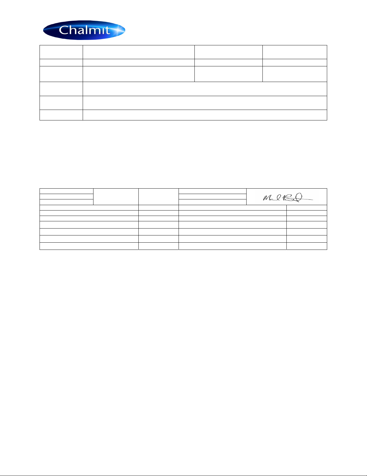
EU/UK-Declaration of conformity
UE-Déclaration de conformité
EU-Konformitätserklärung
Manufacturer Chalmit Address 388 Hillington Road, Glasgow. G52 4BL Scotland UK
Product Curie Elite
(
LED
)
Emer
g
enc
y
Luminaire.
Notified Bod
y
CML B.V. 2776
EU Type Examination Certificate CML 16ATEX3335X
Approved Bod
y
Eurofins CML 2503
UK Type Examination Certificate CML 21UKEX1499X
ATEX/UKEX Coding II 2 GD
ATEX/UKEX Classification Group II Cate
g
or
y
2 GD
Equipment Coding Ex e mb qb IIC T4 Gb or Ex d e mb qb IIC T4 Gb
Ex tb lllC T95°C Db IP6X -20°C Ta +45°C insulated (-20°C Ta +55°C uninsulated)
Ingress Protection IP65
The technical basis, with respect to equivalence of
La base technique, en ce qui concerne l'équivalence de
Die technische Grundlage hinsichtlich der Normen
Protection Standards EN 60079-0, EN 60079-1, EN 60079-5, EN 60079-7, EN 60079-18, EN 60079-28, EN 60079-31
Area Classification EN 60079-10-1 and EN 60079-10-2
of compliance with the EHSRs is valid as there are no chan
g
es which materiall
y
affect the state of technolo
g
ical pro
g
ress of the product.
en conformité avec les EESS est valide puisqu'il n'y a aucun changement qui affecte matériellement l'état de l'évolution technologique du
produit.
zur Erfüllung der GSGA ist gegeben, da keine Änderungen erfolgt sind, die einen Einfluss auf den technischen Stand des Produkts haben.
Terms of the directive: Standard & Date Certified to Standards Date Declared to
Prescription de la directive: Standard & date certifiée à Normes date Déclaré
Bestimmungen der Richtlinie: Standard & Datum Zertifiziert
nach
Standards Datum erklärt
2014/34/EU
Sl 2016 No.1107
Equipment and protective systems intended for use
in potentially explosive atmospheres.
EN 60079-0 : 2012
EN 60079-1 : 2014
2014/34/UE Appareils et les systèmes de protection destinés à
être utilisés en atmosphères potentiellement
explosibles.
EN 60079-5 : 2015
EN 60079-7 : 2015
EN 60079-18:2015
2014/34/EU
Geräte und Schutzsysteme zur bestimmungs-
gemäßen Verwendung in explosionsfähigen
Bereichen.
EN 60079-28 : 2015
EN 60079-31: 2014
2014/30/EU
Regulations 2016
Electromagnetic compatibility EN 55015 : 2019
2014/30/UE Compatibilité électroma
g
nétique EN 61547 : 2009
2014/30/EU Elektroma
g
netische Verträ
g
lichkeit EN 61000-3-2 : 2019
2014/35/EU
Regulations 2016
Low voltage equipment EN 60598-1 : 2015
2014/35/UE Équipements électriques à bas voltage EN 60598-2-22 : 2014
2014/35/EU Niederspannun
g
s
g
eräte / -s
y
steme EN 60529 : 1992+A2:2013
2012/19/EU
Regulations 2012
Waste of electrical and electronic equipment Shell Deluge DTS-01 : 1991
2012/19/UE Déchets d'équipements électriques et électroniques Seismic EN 60068-3-3 : 1993
I-CUEE-03.doc Issue 08 28/04/2021 10
IOM – CURIE ELITE - ZONE 1 RECESSED
2012/19/EU Entsorgung der elektrischen und elektronischen
Geräte / S
y
steme
Nuclear Seismic
IEC 60980-6 : 1993
2011/65/EU
Regulations 2012
RoHS II Directive
Additional
information: The luminaire is capable of withstanding over voltage levels of up to 400V AC for 1 minute and impulse voltage surges
of 4kV.
Informations
complémentaires: Le luminaire peut supporter des niveaux de tensions juqu'à 400V CA pendant 1 minute et des tensions de choc de
4kV.
Zusatzinformation
: Dieser Strahler widersteht Überspannungen bis 400V AC 1 Minute lang sowie Stoßspannungen von 4kV.
On behalf of the Chalmit, I declare that, on the date the equipment accompanied by this declaration is placed on the market, the equipment
conforms to all technical and regulatory requirements of the above listed directives.
En tant que représentant du fabricant Chalmit, je déclare qu'à la date où les équipements accompagnant cette déclaration sont mis sur le
marché, ceux-ci sont conformes à toutes les dispositions réglementaires et techniques des directives énumérées ci-dessus.
Hiermit bestätige ich, im Namen von Chalmit, dass am Tag der Lieferung des Produkts/der Produkte zusammen mit dieser Erklärung das
Gerät/die Geräte alle technischen und regulativen Anforderungen der oben aufgeführten Direktiven erfüllt.
Name and Date
Mark Poutney 28/04/2021
Technical Mana
g
er
Nom et Date Directeur technique
Name und Datum Technischer Leiter
Quality Assurance Notification by: SGS Fimko OY Quality Management System Acreditation: ISO 9001
Notification d'assurance qualité par: 0598 Certification du s
y
stème de
g
estion de la qualité: b
y
/par/durch
Qualitätssicherungsnotifikation durch: Qualitätsmanagementsystem Akkreditierung: Loyd's Register
Certificate No./Certificat N°/Zertifikat Nr. LRQ 4005876
Quality Assurance Notification by: SGS Baseefa
1180
This manual suits for next models
2
Table of contents
Other Chalmit Lighting Equipment manuals


