manuals.online logo
Brands
  1. Home
  2. •
  3. Brands
  4. •
  5. Chamberlain
  6. •
  7. Camera Accessories
  8. •
  9. Chamberlain 923GA User manual

Chamberlain 923GA User manual

BATTERY BOX INSTALLATION
The cold-weather battery kit MUST be located close to the gate
operator’s control box in an area that is not prone to flooding, may be hit
by gate or knocked over.
1. Place the battery box in the selected site near the control box.
2. Remove cover of the battery box. Set the sealed lead-acid battery
(not provided) inside the battery box with the terminals on top.
3. Connect the battery cable with the 20A ATC fuse to the battery (this is
the battery cable harness). Attach the ring terminal on the red wire to
the positive (+) terminal of the battery. Attach the ring terminal on the
black wire to the negative (-) terminal of the battery.
NOTE: Batteries with a capacity other than 75AH may be used. However,
an AH rating significantly less than 75 will decrease cold temperature
performance and is not recommended.
SOURCES
www.batterygiant.com
www.apexbattery.com
www.batteriesplus.com
Manufacturer Part Number Specifications
Jolt XSA12800B 12V, 80AH
Werker WKA12-80C/FR 12V, 80AH
Universal UB12750 12V, 75AH
PowerSonic PS-12750 12V, 75AH
Genesis NP75-12 12V, 77.5AH
CARTON INVENTORY
Wire Tie (4)
Watertight Connector (1)
Battery Box (1) Battery Cable w/ 20A fuse (1) Extension Cable (1)
COLD-WEATHER BATTERY KIT
MODEL 923GA
BATTERIES
Battery Box
Control Box
To reduce the risk of FIRE or INJURY to persons:
• Use ONLY Chamberlain part 923GA.
• DO NOT dispose of the batteries in fire. The cells may explode.
Check with local codes for possible disposal instructions.
• DO NOT open or mutilate the batteries. Released electrolyte is
corrosive and may cause damage to the eyes or skin. It may be
toxic if swallowed.
• Exercise care in handling batteries in order not to short the
battery with conducting materials such as rings, bracelets, and
keys.
• Change the batteries provided with or identified for use with this
product ONLY in accordance with the instructions and limitations
specified in this manual.
• Observe proper polarity orientation between the batteries and
charging circuit.
ATTENTION
AVERTISSEMENT AVERTISSEMENT
AVERTISSEMENT
WARNING
CAUTION
WARNINGWARNING
WARNING
PRECAUCIÓN ADVERTENCIA
ADVERTENCIAADVERTENCIA
The 923GA Cold-Weather Battery Kit is compatible with Chamberlain®
Gate Access Systems GA400D and GA420D. The purpose of the
Cold-Weather Battery Kit is to enable the operator to function in
temperatures as low as -40 °C for short durations. An added benefit of
the kit is to extend the battery backup time for solar powered
applications. The 923GA Cold-Weather Battery Kit is designed to work
with a sealed lead-acid (SLA) battery only (not provided).
BEFORE STARTING
Verify carton inventory below. In addition, a UL Recognized,
BCI Group 24, 12V 75 or 80 AH sealed lead-acid (SLA) battery MUST
be purchased separately. See chart for manufacturers.
NOTES:
• Make sure the battery is fully charged BEFORE installing.
• The battery harness has ring terminals that are to be bolted to the
battery terminals. Select the battery that matches this type of
terminal, otherwise purchase terminals that match the battery.
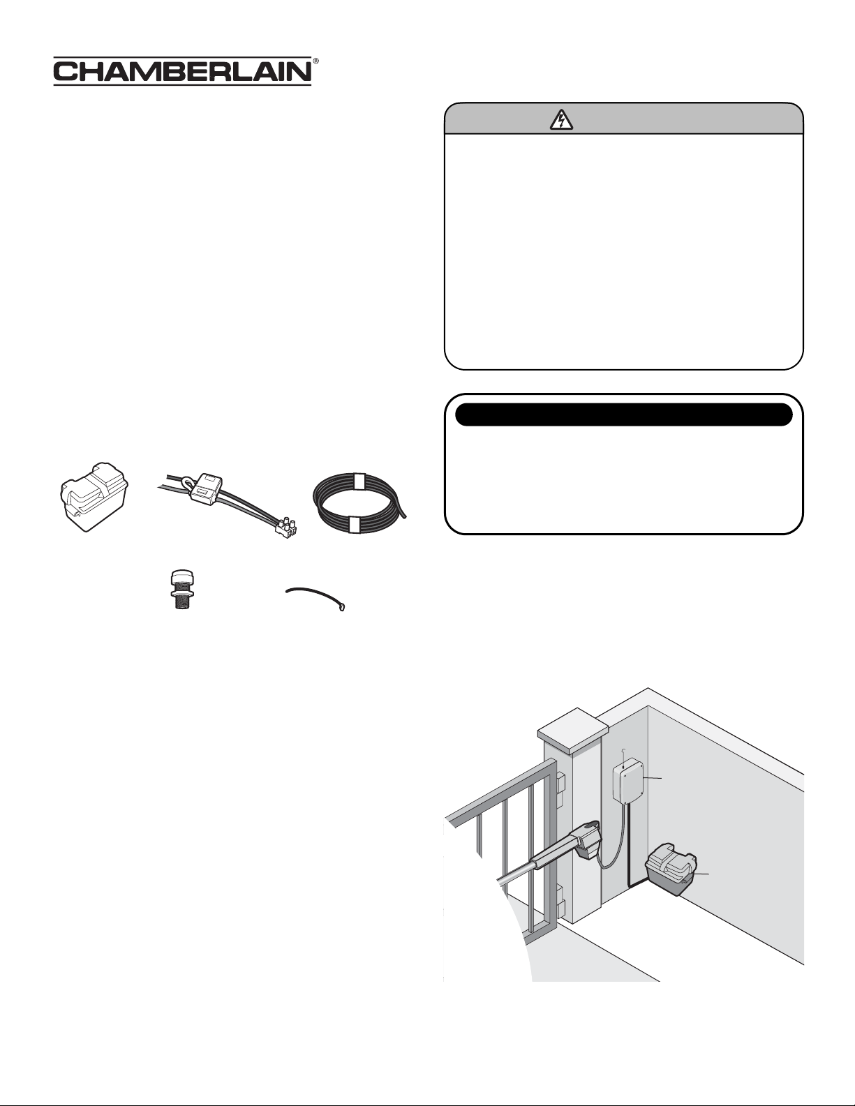
CONNECT TO GATE OPERATOR CONTROL BOX
1. Disconnect all power to the gate operator before proceeding.
2. Use a screwdriver to punch out the plastic knockout at the bottom
of the control box. Install the watertight connector.
3. Feed the non-connector end of the extension cable through the
watertight connector from the inside of the control box. Tighten
the watertight connector until the cable is secure.
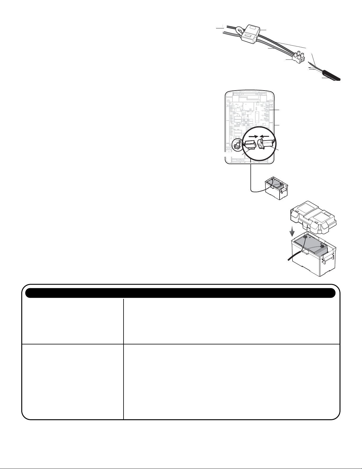
4. Run the extension cable to the battery box and connect the black
wire of the extension cable to the black wire of the terminal block
on the battery cable. Connect the white wire to the red wire.
5. Connect the battery connectors on the control board to the
connector on the extension cable in the control box.
NOTE: Some systems may have both battery connectors in use.
Disconnect one of the internal 7 AH batteries and use the connector to
connect the external battery. The unused 7 AH battery can be removed
from the system.
6. Verify that the gate operator operates correctly.
IMPORTANT NOTE: If the gate operator does not operate correctly, the
wiring may be incorrect. Also, if the battery has been discharged,
disconnect it and charge separately. Refer to troubleshooting for more
tips.
7. Use the wire ties to secure the cables.
8. Reconnect power to the operator.
9. Close the cover on the control box.
10. Place the cover on the top of the battery box. Be sure all drain
holes and air vents are properly opened.
+
–
Terminal Block
Fuse Holder
Black
Red
White
+
–
Control Board
Control Box
18
18
R93
R93
L1
L1
D42
D42
K2
K2
D1
D1
Ø
Z22
Z22
P1
P1
F2
F2
MOV1
MOV1
D1
D1
Q12
Q12
U4
U4
OFF
OFF
MAX
MAX
OPEN
OPEN
SINGLEBUTTON
SINGLEBUTTON
RESET
RESET
STOP
STOP
CHGR
CHGR
OVLD
OVLD
COM
COM
COM
COM
D129
D129
Z4
Z4
U3
U3
D2
D2
D44
D44
C11
C11
C13
C13
C12
C12
D16
D16
F9
F9
R1
R1
Ø
1
R1
R1
ØØ
ØØ
K1
K1
Q22
Q22
F3
F3
K3
K3
K4
K4
R196
R196
F1
F1
Z12
Z12
GATE2
GATE2
GATE1
GATE1
MAGR
MAGR
SOL
SOL
GR
GR
WH
WH
YL
YL
BL
BL
RD
RD
BR
BR
GR
GR
WH
WH
YL
YL
BL
BL
RD
RD
BR
BR
F7
F7
24V
24V
CTRL
CTRL
OVLD
OVLD
TIMER
TIMER
RUNNING
RUNNING
GATE2
GATE2
SET
SET
OPEN
OPEN
LIMIT
LIMIT
SET
SET
CLOSE
CLOSE
LIMIT
LIMIT
LEARN
LEARN
LIMITS
LIMITS
GATE1
GATE1
LEARN
LEARN
XMITTER
XMITTER
LOCK /
LOCK /
ON
ON
OFF
OFF
C69
C69
OFF
OFF
MAX
MAX
J2
J2
Ø
PWR
PWR
ACPWR
ACPWR
/SOLAR
/SOLAR
D8
D8
D4
D4
R9
R9
R329
R329
R27
R27
MOV2
MOV2
R4
R4
C2
C2
BIPARTDELAY
BIPARTDELAY
LOCK
LOCK
GND
GND
Z1
Z1
R1
R1
R2
R2
K5
K5
F12
F12
Q9
Q9
R9
R9
Ø
F8
F8
Q6
Q6
Q1
Q1
J19
J19
R182
R182
C1
C1
Ø1
Ø1
C75
C75
C73
C73
C72
C72
C71
C71
C7
C7
Ø
C66
C66
C65
C65
C68
C68
C33
C33
F11
F11
R186
R186
R42
R42
Ø
R423
R423
J24 J23 3
J24 J23 3
Ø
A 32V
A 32V
3
3
Ø
A 32V
A 32V
J21
J21
30
30
30
30
C64
C64
R22
R22
U2
U2
J18
J18
K6
K6
JU1
JU1
JU1
JU1
JU2
JU2
DB1
DB1
D36
D36
R184
R184
External Battery Connector
Control Board Connector
System does not power up when external
battery is connected.
1. Wires may be swapped. Verify that all wires are properly connected.
2. Battery is not charged. It is possible that the 12V battery (not provided) was not fully charged
when installed. Use a voltmeter to make sure this battery is good and has at least 12V across the
open circuit terminals.
3. Blown fuse. It is possible that a fuse, either in the battery cable harness or on the operator
control board, may have been blown during the installation. If a blown fuse is found, first check
all wiring to make sure it is correct, and then replace the fuse with the same size and type.
System powers up but does not
run correctly.
1. Wires may not be properly connected. Verify all connections for the installation. Batteries are
required for the operator to run.
2. Blown fuse. It is possible that a fuse, either in the battery cable harness or on the operator
control board, may have been blown during the installation. If a blown fuse is found, first check
all wiring to make sure it is correct, and then replace the fuse with the same size and type.
3. Battery is not charged. It is possible that the 12V battery (not provided) was not fully charged
when installed. Use a voltmeter to make sure this battery is good and has at least 12V across the
open circuit terminals.
4. Debris or other obstructions are affecting gate travel. Make sure that the battery box and
connecting wires are clear of the gate. Clear the gate of all obstructions and verify all safety
devices are operating properly.
TROUBLESHOOTING
PROBLEM SOLUTION
FOR TECHNICAL SUPPORT CALL OUR TOLL FREE NUMBER: 1-866-826-4943
© 2008, The Chamberlain Group, Inc.
01-34289B All Rights Reserved
Extension Cable
Battery Cable

Other Chamberlain Camera Accessories manuals

Chamberlain MyQ Business CAPXL Instruction Manual

Chamberlain

Chamberlain MyQ Business CAPXL Instruction Manual

Chamberlain 485EU User manual

Chamberlain

Chamberlain 485EU User manual

Chamberlain 485LM Guide

Chamberlain

Chamberlain 485LM Guide

Chamberlain 922GA User manual

Chamberlain

Chamberlain 922GA User manual

Chamberlain 4228 Guide

Chamberlain

Chamberlain 4228 Guide

Popular Camera Accessories manuals by other brands

for_q FQ-BLT40 manual

for_q

for_q FQ-BLT40 manual

Zacuto 1-EVF-1S user manual

Zacuto

Zacuto 1-EVF-1S user manual

Sony MPK-P9 operating instructions

Sony

Sony MPK-P9 operating instructions

Manfrotto 545B instructions

Manfrotto

Manfrotto 545B instructions

Hohem iSteady MT2 user manual

Hohem

Hohem iSteady MT2 user manual

Westcott 1821 Setup instructions

Westcott

Westcott 1821 Setup instructions

Toshiba IK-TF5H instruction manual

Toshiba

Toshiba IK-TF5H instruction manual

Manfrotto 804RC2 instructions

Manfrotto

Manfrotto 804RC2 instructions

Ikelite DSC-W5 instruction manual

Ikelite

Ikelite DSC-W5 instruction manual

GreenWorks Tools 2918307 manual

GreenWorks Tools

GreenWorks Tools 2918307 manual

Mamiya Mirror-up Cable Release Product Sheets

Mamiya

Mamiya Mirror-up Cable Release Product Sheets

Visceral Psyche Films Leeming LUT PRO III Setup guide

Visceral Psyche Films

Visceral Psyche Films Leeming LUT PRO III Setup guide

VONROC CD801AA Original instructions

VONROC

VONROC CD801AA Original instructions

Light & Motion BLUEFIN HC7 owner's manual

Light & Motion

Light & Motion BLUEFIN HC7 owner's manual

Bosch VGA-PEND-ARM installation guide

Bosch

Bosch VGA-PEND-ARM installation guide

ozonos TRIPOD quick start guide

ozonos

ozonos TRIPOD quick start guide

DeepSea Power & Light HD Multi SeaCam Operator's manual

DeepSea Power & Light

DeepSea Power & Light HD Multi SeaCam Operator's manual

Philips LR14EB4A Specification sheet

Philips

Philips LR14EB4A Specification sheet

manuals.online logo
manuals.online logoBrands
  • About & Mission
  • Contact us
  • Privacy Policy
  • Terms and Conditions

Copyright 2025 Manuals.Online. All Rights Reserved.