Champion-First Electronics GC-318B User manual

Page 1
GC-318BMotherboard
Note to Users
ThisUser’sGuide&TechnicalReferenceareforassistingsystem
manufacturers and end users in setting up and installing the
motherboard.Everyefforthasbeenmadetoensurethattheinfor-
mation in thismanual is accurate. Champion-First Electronics
Limitedisnotresponsibleforprintingorclericalerrors.Informa-
tioninthisdocumentissubjecttochangewithoutnoticeanddoes
notrepresenta commitmentonthepartof Champion-First.For
previousorupdatedmanuals,BIOS,drivers,orproductrelease
information,pleasecontact Champion-First ElectronicsLimited
at http://www.champion-first.com or through any of the means
indicatedonthefollowingpages.
Companiesandproductsmentioned in this manual areforiden-
tificationpurposes only.Productnamesappearing inthismanual
may or may not be registered trademarks or copyrights of their
respectiveowners.
WebSite: http://www.champion-first.com
Email: [email protected]
ProductName: GC-318B
Version: 1.00
Edition: April,2001

GC-318BMotherboard
Page 2
TT
TT
Taa
aa
abb
bb
ble ofle of
le ofle of
le of ContentsContents
ContentsContents
Contents
Chapter 1 Introduction .......................................................3
1.1 Product Features ................................................................ 3
1.2 Features Summary ............................................................. 3
Chapter 2 Installation ......................................................... 4
2.1 InstallationInstructions ....................................................... 4
2.2 MotherboardLayout ............................................................ 5
2.3 Jumper Setting.................................................................... 6
2.4 Function & Installation Instructions...................................... 9
2.4.1ATPowerSupplyConnector........................................... 9
2.4.2ATXPowerSupply Connector ......................................... 9
2.4.3ATKeyboard Connector ................................................. 10
2.4.4Serial(COM1/COM2) PortConnector .............................. 10
2.4.5USB Connector .............................................................. 10
2.4.6PS/2Mouse Connector .................................................. 10
2.4.7Infra-RedConnector........................................................ 10
2.4.8 Reset Switch.................................................................. 10
2.4.9HDD Led ........................................................................ 10
2.4.10Speaker Connector....................................................... 10
2.4.11 Keyboard Lock Switch.................................................. 10
2.4.12Parallel Port Connector ................................................ 11
2.4.13 SDRAM Sockets.......................................................... 11
2.4.14 PCI Slot ....................................................................... 12
2.4.15 ISA Slot ....................................................................... 12
2.4.16FloppyDriveConnector ................................................ 12
2.4.18BIOS ............................................................................ 12
2.4.19ZIFCPU Socket ........................................................... 13
2.4.20CPU Fan Connector ..................................................... 13
Chapter 3 Software Installation.......................................... 14
Chapter 4 AMI BIOS Setup .................................................15
4.1 Standard CMOS Setup ....................................................... 17
4.2 AdvancedCMOSSetup ...................................................... 19
4.3 AdvancedChipsetSetup ..................................................... 19
4.4 PowerManagementSetup .................................................. 19
4.5 PCI/PnP Setup.................................................................... 19
4.6 CPUConfiguration Setup..................................................... 19
4.7 Save Settings and Exit........................................................ 19
4.8 Exit Without Saving............................................................. 19

Page 3
GC-318BMotherboard
Chapter 1
Introduction
1.1 Product Features
The Intel 430VX highest performance motherboard is based on the
all new Intel 430VX chipset with Baby AT form factor to support the
latest Socket 7 including Intel Pentium, AMD K5 / K6 as well as Cyrix
6x86 / 6x86MX processors.
1.2 Features Summary
ThisMotherboardcomes with followingfeatures:
SupportIntelPentium/PentiumwithMMXtechnology,Cyrix6x86/6x86MX,
AMD K5/K6 using Socket 7
Intel430VXChipset
Two DIMM slots Supportingupto64MB Memory Capacity
Support3.3V EDO and SDRAM DIMM
3 x PCI slots, 2 x ISA slots
2x USB ports, 1 xPS/2mouse port, 1 xPS/2Keyboard port, 1 xIrDAport
1 x FDD port, 1 x LPT port, 2 x COM ports
DualIDE ChannelsSupporting FourUltra-DMA33IDE Devices
AdvancedConfigurationPowerInterface(ACPI) Ready.
1MBBIOS, PC99/ACPI/DMI Compliant
AT/ATXPowerSupplyInterface
Baby AT format, 220mm x 173mm PCB

GC-318BMotherboard
Page 4
Chapter 2
Installation
2.1 Installation Instructions
Thissection covers ExternalConnectorsand MemoryConfiguration.Please
refer to the motherboard layout chart for external connectors, slots and I/O
ports. Furthermore, this section lists all necessary connector pin assign-
mentsfor your reference.Thelocations of theconnectors and portsareillus-
tratedin the following figures.Beforeinserting these connectors, pleasepay
attention to the orientations.
NOTICE!!!
1. Makesure to unplug yourpower supply while addingorremoving
system components
2. Alwayswork onanantistatic surfaceto avoidpossibledamage tothe
motherboardor other components fromstaticdischarge.

Page 5
GC-318BMotherboard
PRIMARYIDE(IDE1)
PCI3
PCI2
DIMM1
DIMM2
AT KB Connector
Socket 7
ISA2
1
1
1
1
1
1
PRINTER
USB
COM2
COM1
ISA1
PCI1
430VX
430VX
1
1
1 1 1 1 1
1 1
1
1
1
1
1
JP10
JP9
1
1
J17
J16
J15
J14
J13
1
1
1
1
J
J
J
P4
P2
P3
J
J
J
P45
P41
P42
1
1
JP43
1
1
1
1
1
J6
J7
J8
J9
J1
2.2 Motherboard Layout
1
1
JP10
JP9
JP44-Fan
J3-KB Lock
J11-Speaker
JP18-Fan
JP15-Suspend
JP14-HDD LED
JP19-Reset
JP1-PWR_SW
J10-IR Connector
JP4
JP2
JP3
1
1
1
1
1
1
JP45
JP41
JP42
J17
J16
J15
J14
J13
1
1
1
1
1

GC-318BMotherboard
Page 6
PRIMARYIDE(IDE1)
PCI3
PCI2
DIMM1
DIMM2
AT KB Connecto r
Socke t 7
ISA2
1
1
1
1
1
1
PRINTER
USB
COM2
COM1
ISA1
PCI1
43 0V X
430VX
1
1
1 1 1 1 1
11
1
1
1
1
1
JP10
JP 9
1
1
1
1
1
1
J17
J16
J15
J14
J13
1
1
1
1
J
J
J
P4
P2
P3
J
J
J
P45
P41
P42
1
1
JP 4 3
1
J6
J7
J8
J9
J1
CPUTypeselection:
CPUType&Speed Ratio Bus Freq. RatioJumper
JP42 JP41 JP45 JP3 JP2 JP4
IntelPentium-233 3.5x 66MHz [1-2] [2-3] [2-3] [1-2] [1-2] [1-2]
IntelPentium-200 3.0x 66MHz [1-2] [2-3] [2-3] [1-2] [2-3] [1-2]
IntelPentium-166 2.5x 66MHz [1-2] [2-3] [2-3] [2-3] [2-3] [1-2]
Cyrix6x86MX-PR200GP 166MHz 2.5x 66MHz [1-2] [2-3] [2-3] [2-3] [2-3] [1-2]
Cyrix6x86MX-PR166GP 150MHz 2.5x 66MHz [1-2] [2-3] [2-3] [2-3] [2-3] [1-2]
AMD-K6-PR2-233 3.5X 66MHz [1-2] [2-3] [2-3] [1-2] [1-2] [1-2]
AMD-K6-PR2-200 3.0X 66MHz [1-2] [2-3] [2-3] [1-2] [2-3] [1-2]
AMD-K6-PR2-166 2.5X 66MHz [1-2] [2-3] [2-3] [2-3] [2-3] [1-2]
AMD-K5-PR200 3.0X 66MHz [1-2] [2-3] [2-3] [1-2] [2-3] [1-2]
AMD-K5-PR166 2.5X 66MHz [1-2] [2-3] [2-3] [2-3] [2-3] [1-2]
JP45
JP41
JP42
2.3 Jumper Setting
Remark: Open Close
CPU External Clock(BUS) Frequency Selection
JP45
JP41
JP42
JP45
JP41
JP42
HCLK: 66.8MHz 75MHz 75MHz
PCICLK: 33.4MHz 37.5MHz 32MHz
2.5x3.0x3.5x4.0x4.5x5.0x5.5x
(2/5)(1/3)(2/7)(1/4)(2/9)(1/5)(2/11)
1
1
1
1
1
1
1
1
1
JP4
JP2
JP3
CPU : BUS Frequency Ratio
JP4
JP2
JP3
JP4
JP2
JP3
JP4
JP2
JP3
JP4
JP2
JP3
JP4
JP2
JP3
JP4
JP2
JP3
1
1
1
1
1
1
1
1
1
1
1
1
1
1
1
1
1
1
1
1
1

Page 7
GC-318BMotherboard
CPUTypeselection:
CPUType&Speed Ratio Bus Freq. RatioJumper
JP42 JP41 JP45 JP3 JP2 JP4
IntelPentium-233MMX 3.5x 66MHz [1-2] [2-3] [2-3] [1-2] [1-2] [1-2]
IntelPentium-200MMX 3.0x 66MHz [1-2] [2-3] [2-3] [1-2] [2-3] [1-2]
IntelPentium-166MMX 2.5x 66MHz [1-2] [2-3] [2-3] [2-3] [2-3] [1-2]
IntelPentium-200 3.0x 66MHz [1-2] [2-3] [2-3] [1-2] [2-3] [1-2]
IntelPentium-166 2.5x 66MHz [1-2] [2-3] [2-3] [2-3] [2-3] [1-2]
AMD-K6-III/550 5.5X 100MHz [1-2] [1-2] [1-2] [1-2] [1-2] [2-3]
AMD-K6-III/500 5.0X 100MHz [1-2] [1-2] [1-2] [1-2] [2-3] [2-3]
AMD-K6-III/450 4.5X 100MHz [1-2] [1-2] [1-2] [2-3] [2-3] [2-3]
AMD-K6-III/400 4.0X 100MHz [1-2] [1-2] [1-2] [2-3] [1-2] [2-3]
AMD-K6-2/550 5.5X 100MHz [1-2] [1-2] [1-2] [1-2] [1-2] [2-3]
AMD-K6-2/500 5.0X 100MHz [1-2] [1-2] [1-2] [1-2] [2-3] [2-3]
AMD-K6-2/450 4.5X 100MHz [1-2] [1-2] [1-2] [2-3] [2-3] [2-3]
AMD-K6-PR2-233 3.5X 66MHz [1-2] [2-3] [2-3] [1-2] [1-2] [1-2]
AMD-K6-PR2-200 3.0X 66MHz [1-2] [2-3] [2-3] [1-2] [2-3] [1-2]
AMD-K6-PR2-166 2.5X 66MHz [1-2] [2-3] [2-3] [2-3] [2-3] [1-2]
AMD-K5-PR200 3.0X 66MHz [1-2] [2-3] [2-3] [1-2] [2-3] [1-2]
AMD-K5-PR166 2.5X 66MHz [1-2] [2-3] [2-3] [2-3] [2-3] [1-2]
IBM/CyrixMII-PR366 2.5x 100MHz [1-2] [1-2] [1-2] [2-3] [2-3] [1-2]
IBM/CyrixMII-PR333 3.0x 83MHz [1-2] [2-3] [2-3] [1-2] [2-3] [1-2]
IBM/CyrixMII-PR300 3.0x 75MHz [1-2] [1-2] [2-3] [1-2] [2-3] [1-2]
IBM/CyrixMII-PR300 3.5x 66MHz [1-2] [2-3] [2-3] [1-2] [1-2] [1-2]
IBM/Cyrix6x86MX-PR233 3.0x 66MHz [1-2] [2-3] [2-3] [1-2] [2-3] [1-2]
IBM/Cyrix6x86MX-PR200 2.5x 66MHz [1-2] [2-3] [2-3] [2-3] [2-3] [1-2]
Cyrix6x86MX-PR166GP 2.5x 66MHz [1-2] [2-3] [2-3] [2-3] [2-3] [1-2]
150MHz
Remarks:
- 83MHz & 100MHz Bus Frequency is NOTsuported

GC-318BMotherboard
Page 8
CPUTypeselection:
CPUType&Speed Ratio Bus Freq. RatioJumper
JP42 JP41 JP45 JP3 JP2 JP4
AMD-K6-III/550 5.5x 66MHz [1-2] [2-3] [2-3] [1-2] [1-2] [2-3]
AMD-K6-III/500 5.0x 66MHz [1-2] [2-3] [2-3] [1-2] [2-3] [2-3]
AMD-K6-III/450 4.5x 66MHz [1-2] [2-3] [2-3] [2-3] [2-3] [2-3]
AMD-K6-III/400 4.0x 66MHz [1-2] [2-3] [2-3] [2-3] [1-2] [2-3]
AMD-K6-III/550 5.5X 75MHz [1-2] [1-2] [2-3] [1-2] [1-2] [2-3]
AMD-K6-III/500 5.0X 75MHz [1-2] [1-2] [2-3] [1-2] [2-3] [2-3]
AMD-K6-III/450 4.5X 75MHz [1-2] [1-2] [2-3] [2-3] [2-3] [2-3]
AMD-K6-III/400 4.0X 75MHz [1-2] [1-2] [2-3] [2-3] [1-2] [2-3]
AMD-K6-2/550 5.5X 66MHz [1-2] [2-3] [2-3] [1-2] [1-2] [2-3]
AMD-K6-2/500 5.0X 66MHz [1-2] [2-3] [2-3] [1-2] [2-3] [2-3]
AMD-K6-2/450 4.5X 66MHz [1-2] [2-3] [2-3] [2-3] [2-3] [2-3]
AMD-K6-2/400 4.0X 66MHz [1-2] [2-3] [2-3] [2-3] [1-2] [2-3]
AMD-K6-2/550 5.5X 75MHz [1-2] [1-2] [2-3] [1-2] [2-3] [1-2]
AMD-K6-2/500 5.0X 75MHz [1-2] [1-2] [2-3] [1-2] [2-3] [2-3]
AMD-K6-2/450 4.5X 75MHz [1-2] [1-2] [2-3] [2-3] [2-3] [2-3]
AMD-K6-2/400 4.0X 75MHz [1-2] [1-2] [2-3] [2-3] [1-2] [2-3]
Remarks:
- 83MHz & 100MHz Bus Frequency is NOTsuported

Page 9
GC-318BMotherboard
Thisjumperis used for adjusting CPUworkingvoltage, for this motherboard
design it can auto detect the single voltage CPU or dual voltage CPU.
Thetable of CPUvoltage selection
CoreVoltage J17 J16 J15 J14 J13
2.1V [1-2] [1-2] [1-2] [1-2] [2-3]
2.2V [1-2] [1-2] [1-2] [2-3] [1-2]
2.4V [1-2] [1-2] [2-3] [1-2] [1-2]
2.8V [1-2] [2-3] [1-2] [1-2] [1-2]
2.9V [1-2] [2-3] [1-2] [1-2] [2-3]
3.0V [1-2] [2-3] [1-2] [2-3] [1-2]
3.1V [1-2] [2-3] [1-2] [2-3] [2-3]
3.2V [1-2] [2-3] [2-3] [1-2] [1-2]
3.5V [1-2] [2-3] [2-3] [2-3] [2-3]
J17
J16
J15
J14
J13
1
1
1
1
1
1
1
1
1
1
1
1
1
1
1
1
1
1
1
1
1
1
1
1
1
1
1
1
1
1
1
1
1
1
1
1
1
1
1
1
1
1
1
1
1
PRIMARYIDE(IDE1)
PCI3
PCI2
DIMM1
DIMM2
AT KB Connecto r
Socke t 7
ISA2
1
1
1
1
1
1
PRINTER
USB
COM2
COM1
ISA1
PCI1
43 0V X
430VX
1
1
1 1 1 1 1
11
1
1
1
1
1
JP10
JP 9
1
1
1
1
1
1
J17
J16
J15
J14
J13
1
1
1
1
J
J
J
P4
P2
P3
J
J
J
P45
P41
P42
1
1
JP 4 3
1
J6
J7
J8
J9
J1
2.1V 2.2V 2.4V 2.8V 2.9V
3.0V 3.1V 3.2V 3.5V
J17
J16
J15
J14
J13
CMOS Clear - JP43
JP43 CMOS
(1-2) CMOSClear (momentarily)
(2-3) Normal(Default)
1
1
CPU Core Voltage Selection - J13,J14,J15,J16,J17
Remark: Open Close
GC-318BMotherboard
Page 10
2.4 Function & Installation Instructions
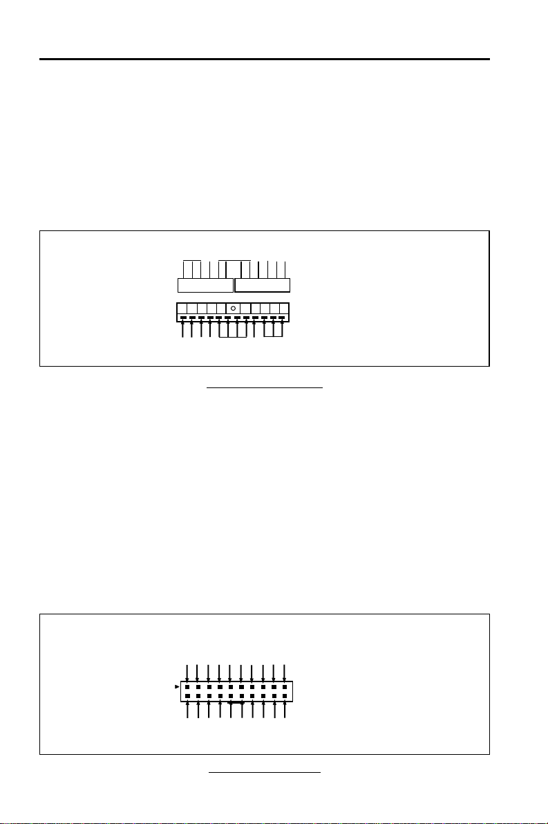
2.4.1 AT Power Supply Connector (12-Pin)
This connector connects to a standard AT power supply. To connect the
leads from the power supply, ensure first that the power supply is not power
on.Most powersuppliesprovide twoplugs, andeachplug containssixwires.
Two of six wires are black and please orient the plugs to the connector so
that 4 black wires are together.
AT Power Connector
At a slight angle, align the plastic guide pins on the lead to their recep-
tacles on the connector. Once aligned, press the lead onto the connector
until the lead locks into place.
2.4.2 ATX Power Supply Connector (20-Pin)
Thisconnectorconnects to an ATX power supply.Theplug from ATXpower
supply will only insert in one orientation because of the different hole sizes.
Find the proper orientation and push down firmly making sure that the pins
are aligned. The system power can be turned off through software control,
like the shut down in Windows 2000 / ME / 98 / 95 start menu. Power man-
agement must be enabled in the system BIOS in order to activate this soft-
off feature. Once the system BIOS receives the power management com-
mand from the OS, it will switch the system power off.
ATX Power Connector
+3.3V
-12V
Ground
PW_ON
Ground
Ground
Ground
-5V
+5V
+5V
Power Connector on
Motherboard
+3.3V
+3.3V
Ground
+5V
Ground
+5V
Ground
PWRGOOD
+5VSB
+12V
PG
+5V
+12V
-12V
Ground
-5V
+5V
Red
White
Black
Blue
Yellow
Red
Orange
Power Plug Power Plug
Power Plugs
fromPower
Supply
Power
Connector on
Motherboard

Page 11
GC-318BMotherboard
2.4.3 AT Keyboard Connector
Thisconnectorsupports a standard IBM-compatiblekeyboard,such as 101/
102 enhanced keyboard (Usea PS/2keyboard adapter inorder toconnect a
PS/2 KB to this AT connector.).
2.4.4 Serial (COM1/COM2) Port Connector
Thismotherboardprovides two compatible serial ports, itcanbe used when
addadditional serial devices.
2.4.5 USB Connector
This 8-pin connector connects to the optional USB ports cable with a
mounting bracket.
2.4.6 PS/2 Mouse Connector (J2)
This 5-pin connector connects to the PS/2 ports cable with a mount-
ing bracket.
2.4.7 Infra-Red Connector (JP10)
This connector supports the optional wireless transmitting and receiving in-
frared module. This module must configure the setting through BIOS setup
and supported by Operation System such as Windows 9x.
2.4.8 Reset Switch (JP19)
This2-pin connectorresetswitch forrebootingyour computerwithouthaving
to turn off your power switch. This method of rebooting is pro-long the life of
the system’s power supply.
2.4.9 HDD LED (JP14)
This connector connects to the hard disk activity indicator, light on when
accessing Hard Disk.
2.4.10 Speaker Connector (J11)
This 4-pin connector connects the system and the speaker.
2.4.11 Keyboard Lock Switch (J3)
This5-pin connector forlocking the keyboardforsecurity purposes,andalso
to connect the system power LED. The system power LED lights when the
7 USB-GND
5 USBDT0+
3 USB DT0-
1 USB-VCC
8 USB-VCC
6 USB DT1-
4 USBDT1+
2 USB-GND
J1 5 MS-CLK
4 GND
3 MS-DATA
2NC
1 VCC
J2
J10
1 VCC
2 NC
3 IRRX
4 GND
5IRTX
GC-318BMotherboard
Page 12
system is powered on.
2.4.12 Parallel Port Connector (26-pin)
Thisconnector supportsthe includedparallelport ribboncable withmounting
bracket. Connect the ribbon cable to this connection and mount the bracket
tothe caseon anopenslot. Itwill thenbeavailable fora parallel printercable.
EXPANSIONCARDS INSTALLATION
Beforeaddingor removing any expansion cards or systemcomponents,
confirmthat you alreadyunpluggedyour power supply.Otherwise,it may
severely damage to your motherboard and expansion cards. Please fol-
lowtheinstallation procedures as below:
1. Checkcarefully if those hardware orsoftwaresettings for your expansion
cards are in the proper position as shown in their User’s Manual.
2. Removeyour computer case’scoverand unscrew the bracketplatefor
those slots needed to insert.
3. Those expansion cards must be aligned on the slots firmly with good
connection.
4. Put on the computer case cover.
5. Ifneeded, setupthe BIOSconfiguration and installthe requireddriversfor
yourexpansion cards.
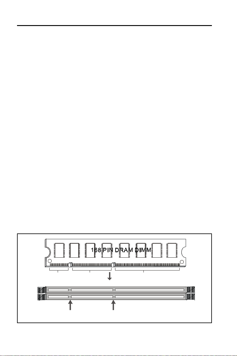
2.4.13 SDRAM Sockets
There are two SDRAM sockets on-board to provide more flexibility for your
systemmemory upgrade. Becausethe number ofpinsare different oneither
sideof the breaks,theDIMM module willonlyfit the 3.3V168-pinunbuffered
forthis motherboard.
3.3V Key
Unbuffered
DRAM Key
20Pins 60Pins 88Pins
Lock
Two DIMM Socket

Page 13
GC-318BMotherboard
168-PinSDRAM ModuleInstallation Diagram
2.4.14 PCI Slot
Thismotherboardprovidesthreefull-length 32-bitPCI slotswith upto133MB/
sec burst data transfer rate.
2.4.15 ISA Slot
Thismotherboard provides two16-bitISA slot.
2.4.16 Floppy Drive Connector (34-Pin)
This connector supports the provided floppy drive ribbon cable. After con-
nectingthe single end to the on-board “FLOPPY”connector, connect the
remainingplugs on the otherendto the floppy drivescorrespondingly.
2.4.17 IDE Connectors (40-Pin)
The IDE connectors support the provided IDE HDD ribbon cable. After
connecting the single end to the board, connect the two plugs at the other
endto yourHDDs.If youinstall twoIDEdevices onthe samecable,you must
configurethe second device toslavemode by settingitsjumper accordingly.
(Refer to your IDE device document for the jumper settings. Pin 20 is re-
movedto preventinsertingin thewrong orientationwhenusing ribboncables
withpin 20 plugged.)
IDEConnectors
2.4.18 BIOS
Pin1 Secondary IDE (IDE2)
Primary IDE (IDE1)
Pin20 be removed

GC-318BMotherboard
Page 14
Themotherboard flashBIOS provides userswith moreflexibilityin upgrading
theirmotherboards.TheflashBIOScanbeeasilyreprogrammedviasoftware.
2.4.19 PGA ZIP CPU Socket
The motherboard provides a ZIF Socket 7. The CPU that attatch with the
motherboard should have a fan on it to prevent overheating. If it is not so,
purchase a fan before you turn on your system.
Notice !!!
Be sure that there is a sufficient air circulation across the processor’s
heatsink by regularly checking that your CPU fan is working. Without
sufficient circulation, the processor could be overheated and it may dam-
ageboththeprocessor and themotherboard.Youmay install an auxiliary
fan,ifnecessary.
Installation step:
1.Turnoff the powerof your system andremoveits cover;
2.Locate the ZIF socket and open it by first pulling the lever sideways away
fromthesocket then upwards to a90-degreeangle;
3.Insertthe CPU with correctorientation
(TheCPU has a cornerpinfor two ofthefour corners, that theCPU only fit
inthe orientation.)
4.Once completely inserted, pull down the socket’s lever to horizontal and
make sure the CPU is firmly locked in the socket.
2.4.20 CPU Fan Connector (JP44)
CPUFancable plug in the 3-pin CPUFanconnector onboard.
Pin1 Sense
Pin2 +12V
Pin3 GND
JP44 CPU FAN
1

Page 15
GC-318BMotherboard
Chapter 3
Software Installation
Note:
Before installation, you must already have Windows 95/98/
2000/MEorWindowsNT4.0installon your computer.
The installation procedure is as below:
1. Make sure that Auto-insert detection is enabled for your CDROM
drive. It should be enabled by default.
2. Insert this CD disk into your CDROM drive.
3. The Explorer screen will then appear, that gives you instructions
forinstallation.
4. There may require restarts of Windows during some software
setup. In these cases, you can just eject then close the CD-tray in
order to get back to the Explorer screen. You can then proceed
with the next step.
You canget moreinformation withopen file:readme.txt in theCD
disk.

GC-318BMotherboard
Page 16
Chapter 4
AMIBIOS Setup
AMIBIOS HIFLEX SETUP UTILITY - VERSION 1.2 1
(C)1998 American Megatrends, Inc. All Rights Reserved
Standard CMOS Setup
Advanced CMOS Setup
Advanced Chipset Setup
Power Management Setup
PCI / Plug and Play Setup
Peripheral Setup
CPU Configuration Setup
Auto-Detect Hard Disks
Change User Password
Change Supervisor Password
Change Language Setting
Auto Configuration with Opti m al Settings
Save Settings and Exit
Exit Without Saving
Standard CMOS setup for changing time, date, hard disk type, etc.
ESC:Exit :Sel F2/F3 :Color F10 :Save & Exit
This GC-318B motherboard comes with the AMI BIOS from AMI
Software Inc. Enter the AMI BIOS program Main Menu by:
1. Turn on or reboot the system. After a series of diagnostic checks,
the following message will appear:
Press <DEL> to enter setup, ESC to skip memory test
2. Press the <DEL> key and the main program screen will appear
as follows.

Page 17
GC-318BMotherboard
3. Using the arrows on your keyboard, select an option, and
press <Enter>. Modify the system parameters to reflect the options
installed in your system. Otherwise you may return to the Main
Menu anytime by pressing <ESC> .
Types of Setup Description
Standard CMOS Setup Sets time, date, hard disk type, types of floppy
drives, monitor type, and if keyboard is installed.
Advanced CMOS Setup Sets Typematic Rate and Delay, Above 1MB
Memory Test, Memory Test Tick Sound, Hit
<Del> Message Display, System Boot Up Se-
quence, and others.
Advanced Chipset Setup Sets chipset-specific options and features.
Power Management Setup Controls power conservation options.
PCI/PnP Setup Sets options related to the PCI bus and Plug
and Play options.
Peripheral Setup Controls I/O Controller-related options.
CPU Configuration Setup This option selects the type of CPU install in the
motherboard. The settings are Auto (AMIBIOS
automatically determines the CPU type).
4. In the Main Menu, “Save Settings and Exit”saves your changes
and reboots the system, and “Exit Without Saving”ignores your
changes and exits the CMOS Setup.

GC-318BMotherboard
Page 18
4.1 Standard CMOS Setup
Selectthe AMIBIOS Setup optionsbychoosing Standard Setup from the
AMIBIOS Setup main menu. Standard Setup options are described be-
low.
FloppyDriveA:andB:
Movethe cursorto thesefieldsvia and andselectthe floppytype. The
settings are 360KB5¼inch, 1.2 MB 5¼inch, 720 KB 3½inch, 1.44MB3½
inch, or 2.88 MB 3½inch.
Primary Master
Primary Slave
Secondary Master
Secondary Slave
Select these options to configure the drive named in the option. Select
AutoDetectIDE toletAMIBIOSautomaticallyconfigurethedrive.Ascreen
witha listofdrive parametersappears.Click on OKto configurethedrive.
AMIBIOS SETUP - STANDARD CMOS SETUP
(C)1998 American Megatrends, Inc. All Rights Reserved
Date (mm/dd/yyyy) : Tue Nov 21,2000 Base Memory: 0 KB
Time (hh/mm/ss) : 16:17:0 6 Extd Memory: 0 MB
Floppy Drive A: 1.44 MB 3 ½
Floppy Drive B: Not Installed
LBA Blk PIO 32Bit
T ype Size Cyln Head WPcom Sec Mode Mode Mode Mode
Pri Master : Auto Off
Pri Slave : Auto Off
Sec Master : Auto Off
Sec Slave : Auto Off
Boot Sector V irus Protection Disabled
A vailable Options: ESC:Exit :Sel
Disabled PgUp/PgDn:Modify
Enabled F1:Help F2/F3:Color

Page 19
GC-318BMotherboard
Type How to Configure
SCSI Select Type. Select Not Installed the drive parameter screen.
The SCSI drivers provided by the SCSI manufacturer should
allow you to configure the SCSI drive.
IDE Select Type. Select Auto to let AMIBIOS determine the param-
eters. Click on OK when AMIBIOS displays the drive param-
eters. Select LBA/Large Mode. Select On if the drive has a ca-
pacity greater than 540 MB. Select Block Mode. Select On to
allow block mode data transfers. Select 32-Bit Transfer. Select
On to allow 32-bit data transfers. Select the PIO Mode. It is best
to select Auto to allow AMIBIOS to determine the PIO mode. If
you select a PIO mode that is not supported by the IDE drive, the
drive will not work properly. If you are absolutely certain that you
know the drive’s PIO mode, select PIO mode 0-5, as appropriate.
CD-ROM Select Type. Select CDROM. Click on OK when AMIBIOS dis-
plays the drive parameters.
StandardMFM Select Type. You must know the drive parameters. Select the
drive type that exactly matches your drive’s parameters.
Non-Standard Select Type. If the drive parameters do not match the drive
MFM parameters listed for drive types 1-46, select User and enter the
correct hard disk drive parameters.
Entering Drive Parameters
Youcanalso enterthehard diskdrive parameters.Thedrive parametersare
Parameter Description
Type The number for a drive with certain identification parameters.
Cylinders The number of cylinders in the disk drive.
Heads The number of heads.
Write The actual physical size of a sector gets progressively smaller as
Precomp- the track diameter diminishes. Yet each sector must still hold
ensation 512 bytes. Write precompensation circuitry on the hard disk
compensates for the physical difference in sector size by boost-
ing the write current for sectors on inner tracks. This parameter
is the track number on the disk surface where write
precompensation begins.
Landing Zone This number is the cylinder location where the heads normally
park when the system is shut down.
Sectors Thenumber ofsectors pertrack. MFMdrives have17sectorspertrack.
RLL drives have 26 sectors per track. ESDI drives have 34 sectors
per track. SCSI and IDE drives have even more sectors per track.
Capacity The formatted capacity of the drive is the number of heads times
the number of cylinders times the number of sectors per track
times 512 (bytes per sector).

GC-318BMotherboard
Page 20
4.2 Advanced CMOS Setup
The AMIBIOS Setup options described in this section are selected
by choosing Advanced CMOS Setup from the AMIBIOS Setup main
menu.
4.3 Advanced Chipset Setup
ChooseChipsetSetupontheAMIBIOS Setup main menu. All Chipset
Setup options are then displayed. AMIBIOS Setup can be custom-
ized.
4.4 Power Management Setup
The AMIBIOS Setup options described in this section are selected
by choosing Power Management Setup from the AMIBIOS Setup
main menu.
4.5 PCI/PnP Setup
Choose PCI/Plug and Play Setup from the AMIBIOS Setup screen
to display the PCI and Plug and Play Setup options.
4.6 CPU Configuration Setup
Thissystem BIOS is capableto detect the CPUtype,say Pentium III,
Pentium II or Celeron. The user is only required to select the CPU
speed. In addition, overclocking option is provided for advanced
users who prefer to run the CPU over the specified clock frequency.
4.7 Save Settings and Exit
Choose Save Setting and Exit from the AMIBIOS Setup main menu.
Type “Y”to exit the BIOS Setup program and saving the values.
Type “N”to return to the Setup program.
4.8 Exit Without Saving
Choose Exit Without Saving from the AMIBIOS Setup main menu.
Type “Y”to exit the BIOS Setup program without saving the values.
Type “N”to return to the Setup program.
The End
Table of contents
Other Champion-First Electronics Motherboard manuals


