100434 - 24 IN. 2-STAGE SNOWBLOWER IMPORTANT SAFETY INSTRUCTIONS
4
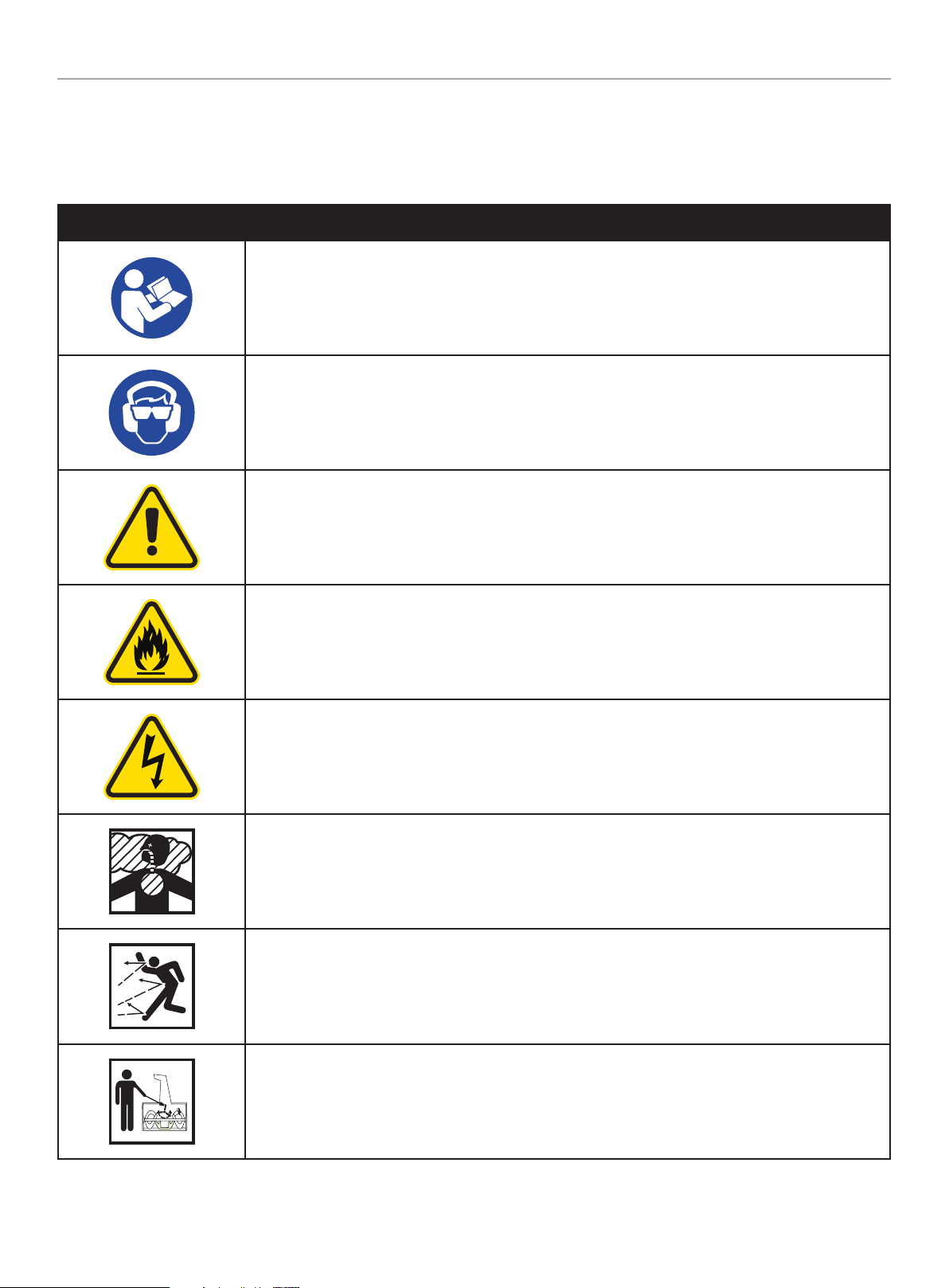
IMPORTANT SAFETY INSTRUCTIONS
WARNING
Cancer and Reproductive Harm – www.P65Warnings.ca.gov
General Safety
1. Read the operating and service instruction manual carefully.
Be thoroughly familiar with the controls and the proper use of
the equipment. Know how to stop the unit and disengage the
controls quickly.
2. Never allow children under 16 years old to operate the
equipment. Never allow adults to operate the equipment
without proper instruction.
3. Thrown objects can cause serious injury. Keep the area of
operation clear of all persons, particularly small children,
and pets. Plan your snow discharge pattern to prevent
throwing material toward cars, structures, roads and people.
4. Exercise caution to avoid slipping or falling, especially when
operating in reverse.
5. Keep in mind that the operator or user is responsible for
accidents or hazards occurring to other people or their
property.
6. Never use the snowblower under the influence of alcohol or
medication, or if you are tired or ill.
Preparation For Use
1. Thoroughly inspect the area where the equipment is to be
used and remove all doormats, sleds, boards, wires, and
other foreign objects.
2. Disengage all clutch handles before starting the motor.
3. Do not operate the equipment without wearing adequate
winter garments. Wear footwear which will improve footing
on slippery surfaces.
4. Adjust the auger housing height to clear gravel or crushed
rock surface.
5. Never attempt to make any adjustments while the engine
is running (except where specifically recommended in the
manual).
6. Let engine and machine adjust to outdoor temperatures
before starting to clear snow.
7. The operation of any powered machine can result in foreign
objects being thrown into the eyes. Always wear safety
glasses or eye shields during operation, or while performing
an adjustment or repair.
Safe Handling of Gasoline
To avoid severe injury or property damage use high levels of care
while handling gasoline. Gasoline is an extremely flammable
substance and the vapors are explosive. Serious personal injury
can occur when gasoline is spilled on yourself or your clothes,
which can ignite. If you come into contact with gasoline, wash
affected areas of skin and change clothing immediately.
1. Use only an approved gasoline container.
2. Extinguish all cigarettes, cigars, pipes and other sources of
ignition prior to working with or near gasoline.
3. Never refuel machine within closed spaces.
4. Never remove gas cap or add fuel while the engine is hot or
running.
5. Allow engine to cool at least two minutes before refueling.
6. Do not over fill fuel tank. Keep fuel level at least ½ inch below
bottom of filler neck to provide space for fuel expansion.
7. Replace gasoline cap and tighten securely.
8. If gasoline is spilled, wipe it off the engine and equipment.
Move machine to another area. Wait 5 minutes before starting
the engine.
9. Never store the machine or fuel container inside where there
is an open flame, spark or pilot light (e.g. furnace, water
heater, space heater, clothes dryer etc.).
10. Allow machine to cool at least 5 minutes before storing.
11. Never fill containers inside a vehicle or on a truck or trailer
bed with a plastic liner. Always place containers on the
ground away from your vehicle before filling.
12. If possible, remove gas-powered equipment from the truck or
trailer and refuel it on the ground. If this is not possible, then
refuel such equipment on a trailer with a portable container,
rather than from a gasoline dispenser nozzle.
13. Keep the nozzle in contact with the rim of the fuel tank or
container opening at all times until fueling is complete.
Do not use gas cans with nozzle lock-open devices.
Operation
1. Do not put hands or feet near or under rotating parts. Keep
clear of the discharge opening at all times.
2. Exercise extreme caution when operating on or crossing
gravel drives, walks, or roads. Stay alert for hidden hazards
or traffic.
3. After striking a foreign object, stop the engine, remove
the spark plug, thoroughly inspect the snowblower for
any damage, and repair the damage before restarting and
operating the snowblower.