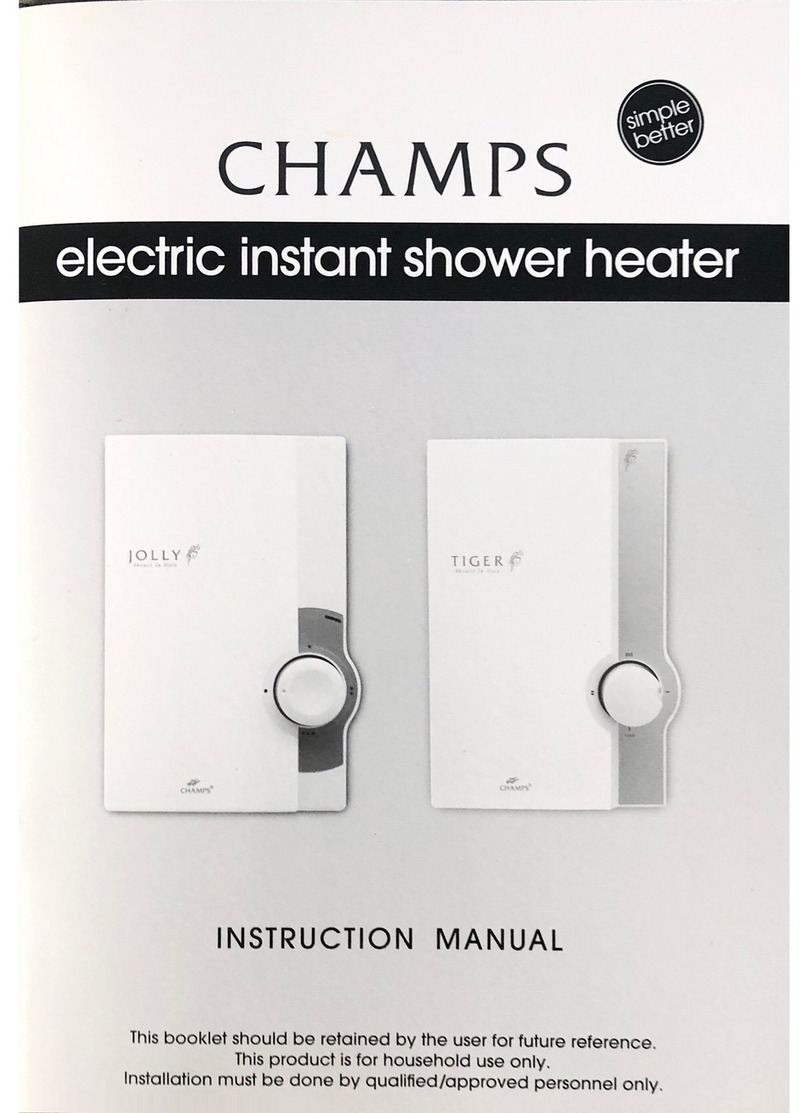
CHAMPS Jolly User manual

11.9.5.3
r“
we“
.—~
v
’f(
w
“WWW”.
.
.
A,
r
n
‘1
g
’4
3
{no—m:
W
'
l
M~MIM.m—'s1.\
INSTRUCTION
MANUAL
Thls
booklet
should
be
relolned
by
the
user
for
future
reference.
This
product
ls
for
household
use
only.
lnclnllnllnn
mud
kn
thn
b“.
n.
ml:
m“;
.
All manuals and user guides at all-guides.com
all-guides.com

Contents
'.
'
I
Introduction
3
2
Package
-
Standard
Contents
4
3
About
Electric
Instant
Shower
Heater
5
A
Site
Requirements
-
Plumbing
&
Electrical
I
7
Product
Installation
5.]
Plumbing
Connections
0'1
G)
5.2
ShowerSet
Installation
IO
‘
5.3
Testing
Plumbing
Connections
II
5.4
Electrical
Connections
I2
5.5
Front
Cover
Mounting
IA
5.6
Testing
Electrical
Connections
I5
Usage
of
Electric
Instant
Shower
Heater
6.]
Operation
Instructions
16
6.2
Safety
Precautions
18
7
Electrical
Information
19
8
Shower
Set
Installation
-
Detailed
Procedure
20
All manuals and user guides at all-guides.com

CHAMPS
JoIIy/
Tiger
Electric
Instant
Shower
Heater
is
intended
for
heating
water
to
the
temperature
suitable
for
a
shower.
Specifications:
CHAMPS
220V]
230V
Ingress
protection
rating
IPX5
’
Inlet
&
outlet
water
connection
w
15mm
(1/2"
ESP)
Minimum
water
row
rate
3t/min
Recommended
water
flow
rate
A
T
belmin
Promissibie
inlet
water
-
0.3MPa
(1-
3
bar)
pressure
‘
,
.
'
'
Recommended
Inlet
water
I
pressure
Dimensions
(LxHxW)
I75x255x105
mm
I75
x255x105
mm
1.4kg
I
4kg
0.1
MPa
(I
bar)
‘
All manuals and user guides at all-guides.com

Bracket
assembly
Hop)
Bracket
assembl
y
(Bottom)
Luxunous
shower
head
Shower
hose
MamUmt
Shower
set‘
Hung
screws
Shower
rod
*
Shower
'
sliding
kit
'
Washer
Stopcock
(optional)
Instruction
manual
All manuals and user guides at all-guides.com

Jolly
Electric
InstantShower
‘
.‘
“
',
Electric
InstantShower.
Heater
Unit
,‘
Heater
Unit
(Frbntview)
t
-
“(Rearview)
Front
cover
Power
selector
knob
Power
indicator
Water
inlet
I
2
3
4
5.
Water
outlet
6
Base
plate
7
Cable
clamp
8
Terminalblock
9
I
Power
selector
(PS)
IO.“
Heating
tank
II.
Thermostat
‘
'
:
;
_
,
Jolly
Electric
Instant
Shower
12.
[Pressure
relief
devrce
(PRD.
optional)
Heater
Unit
(without
Front
Cover)
All manuals and user guides at all-guides.com

Features:
‘1.
’-
a)
High
quality
Polymer
tank:
CHAMPS
tanks
are
constructed
with
high
quality
durable
polymer
material
for
energy
saving
by
minimizing
heat
loss.
IPX5
Splash
Proof
Rating
_
Designed
and
built
with
an
IPX5
rating
that
protects
the
internal
circuits
from
splashing
water.
Energy
8:
Water
Saving
Save
on
utility
bills
as
the
heater
is
only
in
operation
when
in
use.
User-Friendly
Interface
Simple
and
easy
to
use
water
temperature
selector
'
provides
control
over
our
unique
double
heating
elements.
Anti-
Scald
Safety
Device
Prevents
the
water
from
reaching
a
scalding
temperature
for
your
safety.
Massage
Shower
Set
Each
heater
is
equipped
with
a
CHAMPS
massage
shower
set
for
a
complete
shower
experience.
Copper
class
tank:
(models
with
copper
tank
option
only).
CHAMPS
tanks
are
constructed
of
superior
copper.
and
hunt
to
strIngent
specifications
for
reliability,
longevity
and
performance.
All manuals and user guides at all-guides.com
all-guides.com

I
i
ectric
instant
‘3
.
wer
heater
y’
°
Please
check
that
a
20—amp
double
Materials
for
installation:
pole
heater
switch
with
a
minimum
contact
gap
of at
IeaSt
3mm
in
both
poles
is
connected
directly
to
the
mains
and
installed
outside'the
bathroom.
-
If
a
ceiling
rose
connector
is
present,
please
ensure
it
is
rated
for
20-amps
and
the
3
core
cable
between
switch
and
connector
should
be
at
IeaSt
2.5mm2
per
wire.
‘
‘
,
'
Pressure
of
water
supply
from
mains.
Should
be
at
least
0.1
MPa
(I
bar)
and
It
should
not
exceed
0.3MPa
(3bar).
'
Required
minimum
inlet
wgter‘fIOW
rate
is
3Z/min.
.'~‘
.
-
Please
proceed
with
installation
only
if
YOU
meet
the
above
site
requirements.
Flexible
hose
and/or
copper
pipes
Hammer“
Spanner
Cross
head
screw
driver
Power
drill
‘
Flathead
screw
driver
All manuals and user guides at all-guides.com

5.1
Plumbing
Connections
-
Turn
off
electricity
supply.
-
Turn
on
water
supply
and
flush
pipe
to
clear
any
debris
or
impurities.
-
Install
a
mini
valve
at
the
mains
water
supply
in
the
bath
room
for
ease
of
maintenance
and
servicing.
-
Unscrew
the
bottom
and
top
case
mounting
screws
-
Remove
the
front
cover
and
the
knob
together
a,
_
_
.L
,
i
.
Mini
valve
ff:
Ettaglt'mr
-
Take
note
of
the
electricity
and
water
supply
location
and
find
a
suitable
place
for
the
heater
unit.
Make
sure
the
unit
is
in
an
upright
position
All manuals and user guides at all-guides.com

'
Hold
the
heater
over
the
desired
location
and
mark
the
mounting
hole
positions
on
the
wall.
Put
the
heater
down
and
drill
the
holes
as
per
marking.
Insert
wall
plugs
onto
the
-
Align
the
heater
and
screw
it
tightly
onto
the
wall
'
Connect
a
stopcock
to
the
.
.
l
usin
a
flexible
hose
or
co
er
Inlet
pIpe
:5:
2’7)
9
pp
All manuals and user guides at all-guides.com

.
Install
the
shower
set
at
desired
location
with
respect
to
heater
main
unit
-
Note:
Refer
detailed
installation
procedure
given
separately
in
this
booklet.
i
a
-
Connect
shower
hose
to
heater
outlet
-
Place
shower
head
on
shower
holder
(1
1).
-
Completed
plumbing
connections
will
look
like
the
above
picture.
-
Connect
hose
to
shower
head
All manuals and user guides at all-guides.com

5.3
Testing
Plumbing
Connections
.
Turn
on
the
water
supply
and
check
all
connections
for
leakage.
Rectify
if
there
is
any
leakage
found.
-
Test
and
adjust
water
flow
rate
to
approximately
4
to
éllmin.
Contact
us
for
advice
If
water
flow
rate
is
too
high
or
too
low.
Common
errors
to
avoid
for
plumbing
connections:
-
Do
not
add
any
open-close
valve
[stopcock
at
the
outlet.
-
Ensure
heater
unit
is
installed
in
an
upright
position.
-
Do
not
connect
heater
outlet
to
any
mixed
water
faucet.
All manuals and user guides at all-guides.com
all-guides.com

5.4
Electrical
Connections
Proceed
with
electrical
connections
only
after
completing
plumbing
connections.
-
Measure
the
cable
length
required
to
connect
heater
to
the
ceiling
rose
or
heater
switch
-
Cut
the
cable
to
the
measured
length
with
an
allowance
of
10cm.
-
Connect
stripped
end
of
3
wires
one
by
one
to
the
ceiling
rose
[heater
switch
tightly
O
In
order
to
secure
the
cable.
fix
the
conduit
base
along
its
path
from
the
ceiling
rose
/
heater
switch
to
heater
0
Route
the
cable
over
conduit
base
Live
cable
to
terminal
marked
L
.
Neutral
cable
to
terminal
marked
N
Earth
cable
to
terminal
marked
Q
E.
'
Pull
the
cable
inside
the
heater
towards
terminal
block
and
strip
the
cable
to
the
required
length
-
Connect
stripped
end
of
3
wires
(one
by
one)
to
the
terminal
block
using
its
in—built
screws
tightly
All manuals and user guides at all-guides.com

.
Clamp
the
cable
using
the
cable
clamp
with
screws
-
Close
the
ceiling
rose/heater
switch
with
its
cover
and
secure
it
with
screw
-
Cover
the
conduit
base
with
its
cover
I
-
Complete
rest
of
the
electrical
connections
to
be
double
pole
"
heater
switch
located
outside
the
shower
room
All manuals and user guides at all-guides.com

-
Take
the
front
cover
and
cut
the
U-shaped
recess
provided
for
guiding
the
power
cable
at
the
entry
-
Mount
front
cover
on
to
the
base
plate
by
guiding
through
the
ribs
-
Then
secure
casing
using
the
respective
screws
'
Slowly
insert
the
knob
into
the
respective
spindle
-
Completed
installation
of
the
electric
instant
shower
heater.
All manuals and user guides at all-guides.com

5.6
Testing
Electrical
Connections
'
-
Turn
on
water
supply
to
fill
the
tank
with
water,
-
Turn
on
power
supply.
-
Test
for
hot
water
at
different
power
settings.
Common
errors
to
avoid
in
electrical
connections:
-
Do
not
cut
heater
casin
.
to
insert
cable.
Use
only
the
slot
provided
in
the
top
cover.
,
.
Avoid
loose
electrical
connections.
-
Do
not
use
3-pin
power
plug
and
socket
for
electrical
connections.
All manuals and user guides at all-guides.com

6.1
Operationing
Instructions
To
turn
on
the
shower
heater:
-
Turn
on
the
heater
switch.
-
Turn
on
the
water
supply.
'
Turn
the
power
selector
knob
to
LOW,
MEDIUM
or
HIGH.
uni/x.
.
,
«it.
[LOW]
[MEDIUM]
[HIGH]
To
adjust
shower
temperature:
-
Adjust
the
power
selector
knob
to
control
power
settings.
0
(OFF)
-
Cold
setting.
-
[LOW]
—
Low
power
setting
for
economy
and
a
lower
temperature.
-(MEDIUM)
-
Medium
power
setting.
-
[HIGH]
-
High
power
setting
for
maximum
power
and
a
higher
temperature.
To
turn
unit
off:
0
Turn
the
power
selector
knob
to
(OFF).
-
Turn
off
the
water
supply.
-
Turn
off
heater
switch.
All manuals and user guides at all-guides.com
all-guides.com

Jrn
off
stopcock
to
temporarily
turn
off
water
supply:
Ihen
you
want
to
apply
soap
during
shower,
you
can
turn
off
the
water
supply
emporarily
by
turning
off
the
stopcock.
Ie
careful
when
turning
on
the
water
supply
to
resume
using
the
shower
heater.
he
first
flush
of
water
will
be
very
hot.
Urn
the
shower
head
away
from
you
to
avoid
any
contact
from
the
first
flush
of
hot
Mater.Turn
on
the
water
supply
and
test
that
the
water
temperature
is
alright
aefore
you
resume
using
the
shower
heater.
All manuals and user guides at all-guides.com

6.2
Safety
Precautions
-
Do
not
use
shower
heater
if
water
pressure
is
less
than
1
bar.
-
Do
not
use
shower
heater
if
water
flow
rate
is
lower
than
3(lmin
or
higher
than
8!]
min.
-
Children.
elderly,
physically
disabled
or
any
individual
who
has
difticulty
in
operating
the
shower
heater
safely.
should
not
be
allowed
to
use
the
shower
heater
without
supervision.
-
Do
not
use
if
the
spray
head
is
blocked.The
spray
head
must
be
descaled
regularly.
-
WARNING:
Do
not
switch
on
if
there
Is
a
possibility
that
the
water
in
the
heater
is
frozen.
Stop
using
immediately
when:
-
Heater
unit
is
damaged.
-
Shower
head,
shower
hose
or
any
accessory
is
damaged.
-
No
water
flow
during
operation.
-
Heater
functions
significantly
different
from
usual
operation.
Note:
Turn
off
shower
and
Water
supply.
Contact
us
for
assistance
if
any
of
the
above
occurs.
All manuals and user guides at all-guides.com

1.
Terminal
block
4.
Heating
element
1
2.
Thermostat
5.
Heating
element
2
3.
Microswitches
6.
Indicator
lights
All manuals and user guides at all-guides.com

-nsg-gnqgspeiajedisegedl.
C
-
Take
one
bracket,
position
it
as
above
and
open
the
end
cover.
.
Choose
your
preferred
location
with
respect
to
the
heater
unit
and
mark
the
lowest
point
of
bracket
as
shown
-
Take
out
the
bracket
and
mark
a
point
exactly
15mm
abovethe
earlier
marking
All manuals and user guides at all-guides.com
Other manuals for Jolly
1
This manual suits for next models
1
Other CHAMPS Plumbing Product manuals
Popular Plumbing Product manuals by other brands

Finnleo
Finnleo NorthStar Series owner's manual

Moen
Moen T590 Series quick guide

American Standard
American Standard Retrospect Collection Pedestal Sink 0066.000 Specifications

Flomasta
Flomasta 5059340064734 manual

Spirax Sarco
Spirax Sarco FT Series Installation and maintenance instructions

KWC
KWC 1922 10.222.023 Specifications

Hagleitner
Hagleitner XIBU SEAT DISINFECT analog installation instructions

Sanitec
Sanitec Keramag Flushcontrol 1000 N GLT Mounting instruction

Kohler
Kohler K-14402 Homeowner's guide

Kohler
Kohler K-3148 K-3150 Homeowner's guide

Price Pfister
Price Pfister Pfister F-WK1-68 manual

Controlli
Controlli 3F Series quick start guide