Channel Master4 75 User manual
Instruction and Assembly Manual
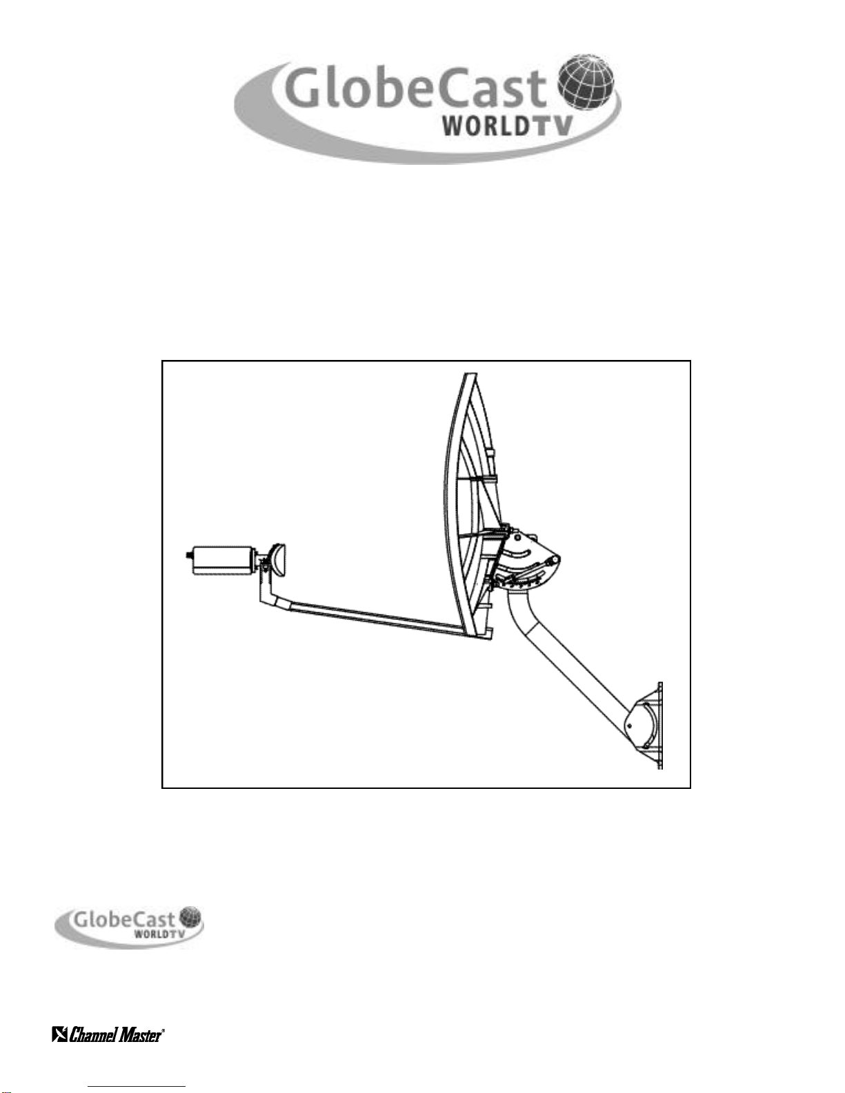
75 Elliptical Antenna System
©2002 Channel Master LLC
Printed in U.S.A.
8000915-02
11/02
7291 NW 74th Street • Miami, FL 33166
GlobeCast Technical Service: (888) 988-5288
Manufactured By:

DANGER!!!
WATCH FOR WIRES! Installation of this product near power lines is dangerous. For your own safety,
follow these important safety rules.
1. Perform as many functions as possible on the ground.
2. Watch out for overhead power lines. Check the distance to the power lines before starting
installation. We recommend you stay a minimum of 6 meters (20 feet) from all power lines.
3. Do not use metal ladders.
4. Do not install antenna or mast assembly on a windy day.
5. If you start to drop antenna or mast assembly, get away from it and let it fall.
6. If any part of the antenna or mast assembly comes in contact with a power line, call your local power
company. DO NOT TRY TO REMOVE IT YOURSELF! They will remove it safely.
7. Make sure that the mast assembly is properly grounded.
WARNING!!!
Assembling dish antennas on windy days can be dangerous. Because of the antenna surface, even slight winds
create strong forces. For example, a 1.0m antenna facing a wind of 32 km/h (20 mph) can undergo forces of 269
N (60 lbs). Be prepared to safely handle these forces at unexpected moments. Do not attempt to assemble, move
or mount a dish on windy days or serious, even fatal accidents may occur. The manufacturer is not responsible or
liable for damage or injury resulting from antenna installations.
WARNING!!!
Antennas improperly installed or installed to an inadequate structure are very susceptible to wind damage. This damage
can be very serious or even life threatening. The owner and installer assumes full responsibility that the installation is
structurally sound to support all loads (weight, wind & ice) and properly sealed against leaks. The manufacturer will not
accept liability for any damage caused by a satellite system due to the many unknown variable applications.
WARNING!!!
Antenna installations requiring the installer to work elevated above the ground level should be performed only by trained
professional installers. Failure to comply may result in personal injury or death.
This Installation Manual provides all the information you require to install your system. The instructions are fairly simple,
providing step-by-step instruction for system installation. However, it will require skills in construction, wiring and
assembly to correctly complete the installation.
WARNING: All satellite dish systems must be properly grounded. National and local electrical codes may
require you to ground the dish directly and to insert a grounding block in the coaxial cables running from the
dish to the receiver inside the building. Before beginning installation, carefully read the section on grounding
the dish.
INTRODUCTION
1
ASSEMBLYTOOLS REQUIRED
This installation requires you to:
• Use hand tools such as a hand drill
• Determine whether water pipes, electrical wiring or gas lines are close to the installation area
• Route coaxial cable through walls and under floors
• Use a compass, protractor and carpenter’s level
• Use a ladder to climb structures
•Know your local and national grounding codes
If you feel you do not have the experience to perform these tasks, contact your satellite retailer to arrange for installation.
You will need the following tools:
• #1 Phillips Screwdriver • Carpenter’s Level
• 1/2 or 13 Hex Wrench, open or combination end • Compass
• Electric Drill and Bits • Protractor
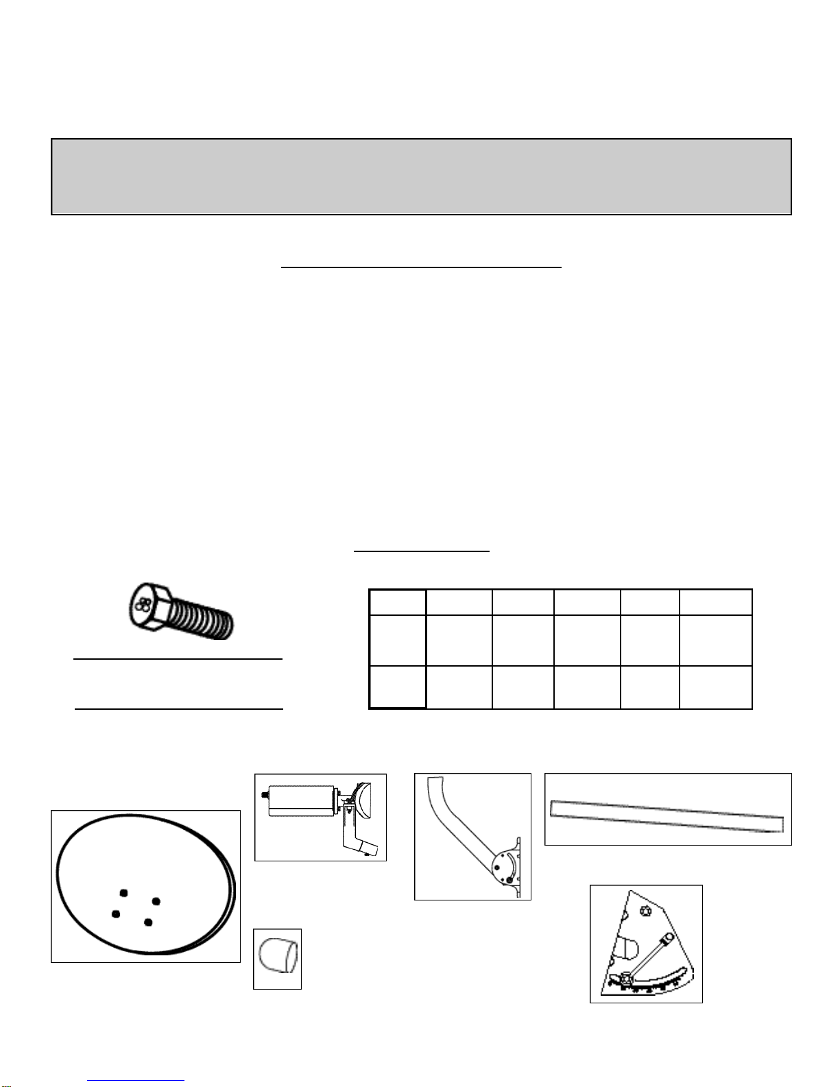
BOLT TORQUE
M6 M8 M10 M12 M16 M20
9.5 24 43 79 195 353
N-m N-m N-m N-m N-m N-m
7 18 32 58 144 260
ft-lbs. ft-lbs. ft-lbs. ft-lbs. ft-lbs. ft-lbs.
GRADE 8.8 (8G) - GOLD COLOR
APPLY 24 N-m (18 ft.-lbs.)
OF TORQUETO M8 BOLT
NOTE:TORQUE FOR M8 ROUND HEAD, SQUARE NECK BOLT IS 16.3 N-m (12 ft-lbs.)
75E Elliptical Dish
75E Az/El Clamp
Mount Assembly
2” diameter
Universal
Mount Assembly
75E Satellite
LNB/Feedhorn Clamp
Assembly
Satellite Feed Support Arm
1 LNB
Weather
Cap
Your 75E Elliptical Dish Kit comes with the following components:

2
MOUNTING LOCATIONS
Key points to remember when installing your 75E Elliptical Antenna System:
•Do not drill any holes until you’ve confirmed the best location for the dish.
• Make sure the installation of the dish conforms to local electrical and building codes, zoning requirements and other
applicable laws and regulations. If you are unsure, contact your local electrician or building inspector for assistance.
•For possible periodic removal of snow, choose a site that is easily accessible.
•Ensure there are no visible obstructions between the dish and your line of sight to the satellites. Keep in mind that trees will
grow up and outward and may eventually block the signal.
•The maximum allowable length for the RG-6 coaxial cable connecting the receiver to your dish is 125 feet.
• Use only RG-6 grade coaxial cable. Using lower grade RG-59 coaxial cable may result in excessive signal loss and
poor reception. Cable grade type is indicated on the outer jacket.
• Do not install the dish:
• Under power lines
• Where it may be easily tampered with
• Where it is exposed to high winds
• During windy or stormy conditions
Your dish must be mounted on a solid base. To ensure your dish doesn’t move in windy conditions, choose a location where
it can be securely fastened. The mounting surface should be rigid and solid.
IMPORTANT:The Elliptical Dish has a minimum turn radius of +/_35 degrees. If you are mounting the dish on the
side of your house, check the assembled dish and mounting pole to see if you can rotate the dish in the desired
azimuth setting. If you can’t rotate the dish, choose an alternate location.
Key things to remember when choosing a mounting location:
•The mounting surface should be flat, even and in good condition.
•If you install the dish on the roof or side of your house, be sure to attach the bolts into a building stud, rafter or other
solid surface.
•When mounting on the roof of your house, use silicon sealant around the holes where the base of the universal mount
meets the mounting surface. This will prevent the roof from leaking.
• We do not recommend:
• Mounting the dish on a railing
• Installing the dish on aluminum or vinyl siding (these are unlikely to be structurally sound)
• Keep grounding requirements in mind.
3
DISH ASSEMBLY
Step 1: To avoid losing any hardware components,
select a clear area on the ground for dish
assembly.
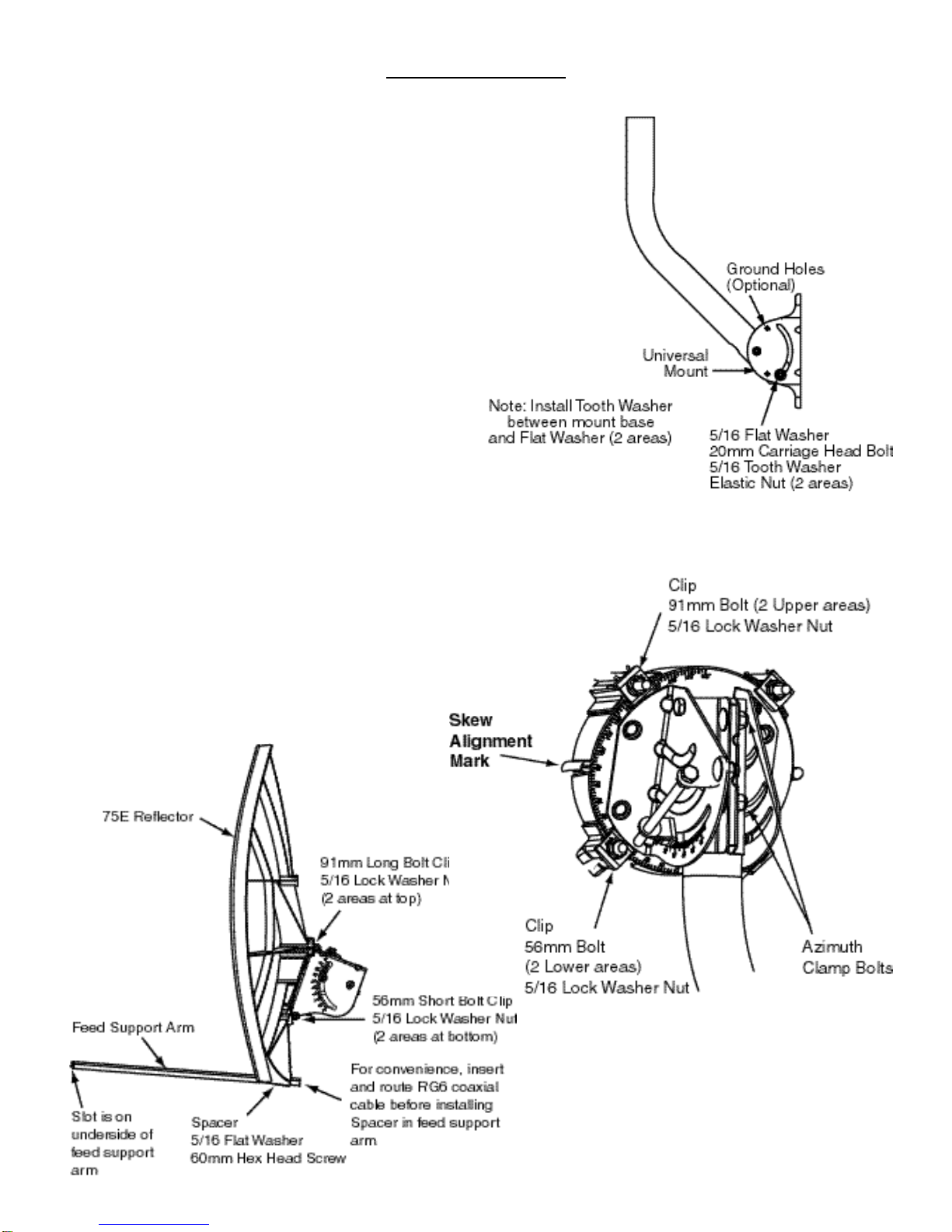
Step 2: On the Universal Mount, insert the (2) 20 mm
Carriage Head Bolts (Mast Adjusting Bolts),
through the mast and the curved slot of the
mount (Figure A).
Step 3: Attach the dish to the Clamp Mount Assembly
using the (2) 91mm and (2) 56mm long
Carriage Head Bolts (Antenna Mounting Bolts-
Painted Head), (4) Skew Lock Clips, (4) Lock
washers and (4) Nuts (see Figure B). Before
tightening the (4) bolts, refer to Skew Setting
Chart on Page 8 & 9 for the correct skew setting
for your geographic location.
Note: For single feed systems, tighten and torque the 4
bolts now as further adjustment will not be required.
Step 4: Pre-route the RG6 Coaxial Cable through the
Feed Support Arm then attach the Feed
Support arm to the dish using the 60mm Screw
Bolt, 5/16 Flat Washer, Spacer and Nut, making
sure the Feed Support Arm and Spacer Sleeve
are positioned as shown in Figure C.
Important: Installation of the Spacer is mandatory to
maintain rigidity. Ensure you tighten the Feed Support
Arm securely.
FIG. A
FIG. B
FIG. C

4
Step 1: Determine the direction in which to point the dish. Refer
to the Satellite Alignment Chart on Page 8 & 9. Record
value below.
“Initial Setting” starting reference from the Locator Chart
Azimuth Elevation Skew
________ ________ Set during Az/El
Mount Attachment
to the Dish
Step 2: Use a compass to determine roughly where to point
your dish.
Step 3: Choose a dish installation location with a clear line of
sight to the satellite based on the settings you recorded
earlier. There should be no trees, buildings or other
obstructions between the dish and the satellite. Do you
have a clear line of sight to the satellite?
•If YES, go to Step 4 and continue with the installation.
•If NO, find another location.
NOTE: To ensure an accurate compass reading, stay away from
large metal objects. To double-check accuracy, take multiple read-
ings several feet apart.
Step 4: At the dish install site, hold a compass level and still in
the palm of your hand. When the needle stops rotating
(dark half of the needle always points north), slowly
rotate the body of the compass so that the "N" marking
is aligned with the dark half of the needle. Locate the
tick mark on the compass edge corresponding to the
SAT azimuth number you wrote down earlier. This is the
direction in which to point your dish to receive signals.
TIP: Use a stick or other distant object to mark the “initial setting”
compass azimuth direction for SAT. Figure D).
Step 5: Estimate the satellite elevation (angle) settings you
recorded earlier, using a protractor. Check any obstruc-
tions at that elevation. If there are obstructions, then
select an alternate location for the dish.
IMPORTANT: When evaluating the install location, make sure
there are no trees, branches or objects visually obstructing the
dish and the general direction of the satellite. Also, keep in
mind that trees grow up and outward and may eventually block
the signal.
LOCATING THE SATELLITE
Azimuth
Elevation
FIG. D
5
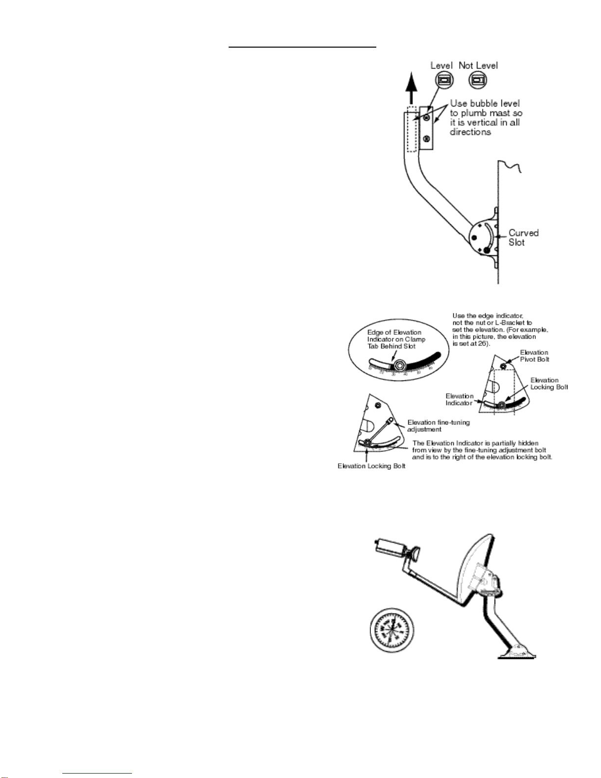
Step 1: Ensure mast is plumb before drilling any holes. Hold
the Universal Mount in place on the mounting area.
Use a carpenter’s level to plumb the antenna mast’s
straight section. If the bubble levels (horizontal and
vertical) are not centered, rotate the mast (in the
curved slot) until it is plumb. Then lock it in place by
securely tightening the Mast Adjusting Bolts (see
Figure E).
IMPORTANT: Initially finding the correct satellite signal and
turning to the satellite will be more difficult if the mast is not
plumb. Ensure the mast is plumb.
Step 2: Drill holes in the structure on which you are mounting
the dish to match the holes in the base of the
Universal Mount.
Step 3: Secure the Universal Mount with appropriate surface
screws (not included). Check the mount for move-
ment. An improperly secured mount will reduce signal
reception and reliability at a later date.
Step 4: Slide the Dish/Clamp Mount Assembly onto the mast
by loosening the (2) Azimuth Clamp Bolts (see Figure
B) and the Elevation Pivot Bolt just enough to slide the
assembly until it makes contact with the Elevation
Pivot Bolt (see Figure F). Tighten the Elevation Pivot
Bolt just enough to hold it in place on the mast.
Step 5: POLARIZATION SETTING:Polarization of the feed is
not needed. It should be set to zero from the factory.
Step 6: ELEVATION SETTING: Loosen the (2) Elevation
Locking Bolts sufficiently about 1 to 2-turns from tight
on either side of the Clamp Mount Assembly. Then
using the Fine Tuning Elevation Adjustment Bolt care-
fully adjust the dish elevation to the setting you record-
ed earlier. Tighten the (2) Elevation Locking Bolts and
re-check the dish elevation setting to ensure the set-
ting has not changed. (See Figure F).
Step 7: INITIAL AZIMUTH SETTING. Using your compass,
point the Feed Support Arm in the direction correspond-
ing to the azimuth setting (see Figure G). Draw a vertical
mark overlapping the Clamp Mount Assembly and the
mast. This mark will provide you with the approximate
starting reference point when you’re ready to find and
tune to the satellite.
ATTACHING THE DISH
FIG. E
FIG. F
FIG. G
6
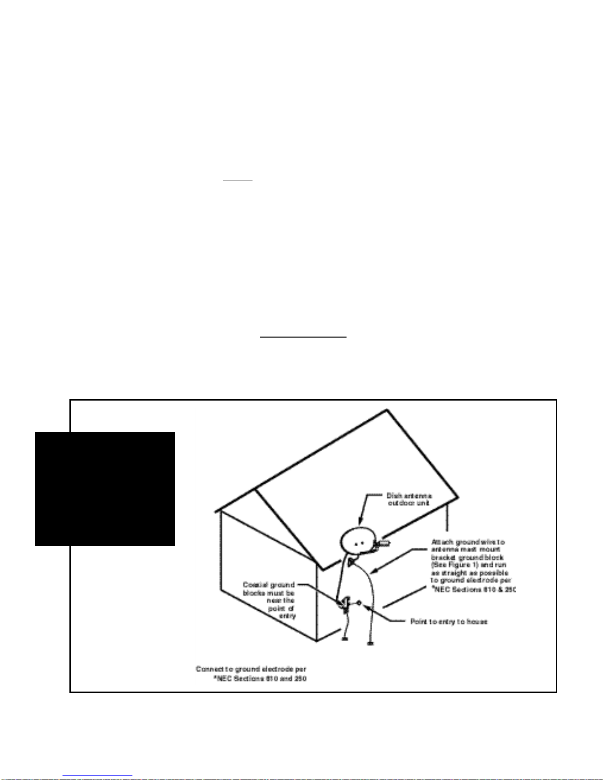
GROUNDING
Step 8: Connect one end of the RG6 coaxial cable to the LNB feedhorn assembly. To install Weather Cap, gently bend the cable
to carefully fit the Weather Cap onto the LNB. Insert cap only about 1/2 inch. Avoid sharp bends to the cable.
Step 9: Before beginning the Tuning to the Satellite process, now is a good opportunity to sufficiently loosen the (2) azimuth
clamp bolts, the elevation pivot bolt and the (2) Elevation Locking Bolts and allow the dish to naturally settle on the
dish pole. While moving the dish back and forth on the pole, slowly and evenly torque all Azimuth Clamp Bolts,
Elevation Pivot Bolt and Elevation Locking Bolts. Eventually tighten all bolts to allow the Azimuth and Elevation Clamp
assembly to be firmly secured on the pole. The dish should not be able to be rotated on the pole with both hands.This
step will be helpful in minimizing dish movement after tuning.
Step 10: FINE TUNING: Follow instructions in the Satellite Receiver Manual or use signal strength measuring device for final
adjustments to obtain maximum antenna performance. Rotate antenna and Az-El cap, pointing to the correct compass
reading that was recorded earlier. Slowlysweep the antenna in azimuth until a signal is found. If desired signal is not
found, increase or decrease the elevation setting (in 1/2˚ increments) and repeat the azimuth sweep. Alternate between
elevation and azimuth fine tuning to reach maximum signal strength until no further improvement is detected. Tighten
and torque all hardware, referring to the Torque Chart on Page 1.
The National Electric Code
is published by the
National
Fire Protection Association
1 Batterymarch Park
Quincy, Massachusetts, 02269-9959
and may be available at
your local public library
General Grounding Requirements for Outdoor Unit
Refer to National Electric and Local Codes for complete requirements.
7
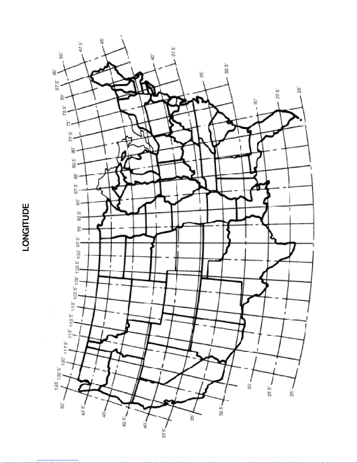
LATITUDE

8
TELSTAR 5 SATELLITE 97˚ W IN 25˚ INCREMENTS
LAT. LONG. AZ EL SKEW
25 80.0 221 55 122
25 82.5 215 57 118
25 85.0 209 58 114
25 87.5 202 59 109
25 90.0 195 60 105
25 92.5 188 60 100
25 95.0 180 61 94
25 97.5 173 61 89
25 100.0 166 61 84
27.5 75.0 230 50 126
27.5 77.5 225 51 123
27.5 80.0 219 53 119
27.5 82.5 213 54 116
27.5 85.0 207 55 112
27.5 87.5 200 56 108
27.5 90.0 194 57 103
27.5 92.5 187 58 99
27.5 95.0 180 58 94
27.5 97.5 173 58 89
27.5 100.0 167 58 84
27.5 102.5 160 57 80
27.5 105.0 154 57 75
30 75.0 229 48 123
30 77.5 223 49 120
30 80.0 218 50 117
30 82.5 212 52 113
30 85.0 206 53 110
30 87.5 199 54 106
30 90.0 193 54 102
30 92.5 186 55 98
30 95.0 180 55 93
30 97.5 173 55 89
30 100.0 167 55 85
30 102.5 161 55 81
30 105.0 155 54 76
30 107.5 150 53 72
30 110.0 144 52 69
30 112.5 139 51 65
30 115.0 135 50 62
32.5 75.0 227 45 120
32.5 77.5 222 47 118
32.5 80.0 216 48 115
32.5 82.5 211 49 111
32.5 85.0 205 50 108
32.5 87.5 199 51 105
32.5 90.0 192 51 101
32.5 92.5 186 52 97
32.5 95.0 180 52 93
32.5 97.5 173 52 89
32.5 100.0 167 52 85
32.5 102.5 162 52 81
32.5 105.0 156 51 78
32.5 107.5 151 51 74
32.5 110.0 146 50 71
32.5 112.5 141 49 67
32.5 115.0 136 47 64
32.5 117.5 132 46 61
32.5 120.0 128 45 58
LAT. LONG. AZ EL SKEW
35 75.0 226 43 118
35 77.5 221 44 115
35 80.0 215 45 113
35 82.5 210 46 110
35 85.0 204 47 107
35 87.5 198 48 103
35 90.0 192 49 100
35 92.5 186 49 96
35 95.0 180 49 93
35 97.5 174 49 89
35 100.0 168 49 86
35 102.5 162 49 82
35 105.0 157 48 79
35 107.5 151 48 75
35 110.0 146 47 72
35 112.5 142 46 69
35 115.0 137 45 66
35 117.5 133 44 63
35 120.0 129 43 61
37.5 75.0 225 41 116
37.5 77.5 220 42 114
37.5 80.0 215 43 111
37.5 82.5 209 44 108
37.5 85.0 203 45 105
37.5 87.5 197 45 102
37.5 90.0 191 46 99
37.5 92.5 185 46 96
37.5 95.0 179 46 93
37.5 97.5 174 47 89
37.5 100.0 168 46 86
37.5 102.5 162 46 83
37.5 105.0 157 46 80
37.5 107.5 152 45 77
37.5 110.0 147 44 74
37.5 112.5 143 44 71
37.5 115.0 138 43 68
37.5 117.5 134 41 65
37.5 120.0 130 40 63
37.5 122.5 127 39 61
37.5 125.0 123 38 59
40 70.0 234 36 118
40 72.5 229 37 116
40 75.0 225 38 114
40 77.5 220 40 112
40 80.0 214 40 109
40 82.5 209 41 107
40 85.0 203 42 104
40 87.5 197 43 101
40 90.0 191 43 98
40 92.5 185 43 95
40 95.0 179 44 92
40 97.5 174 44 89
40 100.0 168 44 86
40 102.5 163 43 83
40 105.0 157 43 81
40 107.5 152 42 78
40 110.0 148 42 75
40 112.5 143 41 72
40 115.0 139 40 70
40 117.5 135 39 67
40 120.0 131 38 65
40 122.5 127 37 63
40 125.0 124 35 61

9
AZ = Azimuth Heading, Direct Compass
Reading (Magnetic Deviation has
been included in the chart.)
EL = Elevation in Degrees, Direct Reading
SKEW = Antenna “Tilt” setting using the Az/El
mount skew scale.
LAT. LONG. AZ EL SKEW
42.5 70.0 233 34 116
42.5 72.5 229 35 114
42.5 75.0 224 36 112
42.5 77.5 219 37 110
42.5 80.0 214 38 108
42.5 82.5 208 39 105
42.5 85.0 203 39 103
42.5 87.5 197 40 100
42.5 90.0 191 40 98
42.5 92.5 185 41 95
42.5 95.0 179 41 92
42.5 97.5 174 41 89
42.5 100.0 168 41 87
42.5 102.5 163 41 84
42.5 105.0 158 40 81
42.5 107.5 153 40 79
42.5 110.0 148 39 76
42.5 112.5 144 38 74
42.5 115.0 139 38 71
42.5 117.5 135 37 69
42.5 120.0 132 36 67
42.5 122.5 128 35 65
42.5 125.0 125 33 63
45 70.0 233 32 114
45 72.5 229 33 113
45 75.0 224 34 111
45 77.5 219 35 108
45 80.0 214 35 106
45 82.5 208 36 104
45 85.0 203 37 102
45 87.5 197 37 99
45 90.0 191 38 97
45 92.5 185 38 94
45 95.0 180 38 92
45 97.5 174 38 90
45 100.0 168 38 87
45 102.5 163 38 85
45 105.0 158 38 82
45 107.5 153 37 80
45 110.0 148 37 77
45 112.5 144 36 75
45 115.0 140 35 73
45 117.5 136 34 71
45 120.0 132 33 69
45 122.5 128 32 67
45 125.0 125 31 65
47.5 70.0 233 29 113
47.5 72.5 229 30 111
47.5 75.0 224 31 109
47.5 77.5 219 32 107
47.5 80.0 214 33 105
47.5 82.5 209 34 103
47.5 85.0 203 34 101
47.5 87.5 197 35 99
47.5 90.0 191 35 96
47.5 92.5 186 35 94
47.5 95.0 180 35 92
47.5 97.5 174 35 90
47.5 100.0 168 35 87
47.5 102.5 163 35 85
47.5 105.0 158 35 83
47.5 107.5 153 34 81
47.5 110.0 148 34 78
47.5 112.5 144 33 76
47.5 115.0 140 33 74
47.5 117.5 136 32 72
47.5 120.0 132 31 70
47.5 122.5 129 30 68
47.5 125.0 125 29 67
LAT. LONG. AZ EL SKEW
50 70.0 234 27 111
50 72.5 229 28 109
50 75.0 225 29 107
50 77.5 220 30 106
50 80.0 215 30 104
50 82.5 209 31 102
50 85.0 204 32 100
50 87.5 198 32 98
50 90.0 192 32 96
50 92.5 186 33 94
50 95.0 180 33 92
50 97.5 174 33 90
50 100.0 169 33 87
50 102.5 163 32 85
50 105.0 158 32 83
50 107.5 153 32 81
50 110.0 147 31 79
50 112.5 144 31 77
50 115.0 140 30 75
50 117.5 136 29 74
50 120.0 132 29 72
50 122.5 129 28 70
50 125.0 125 27 68

MANUFACTURER’S ANTENNA/MOUNT/LNB
LIMITED TWELVE (12) MONTH WARRANTY
This equipment is warranted to be free from defects in material and workmanship under normal use and service.
The manufacturer shall repair or replace defective equipment, at no charge, or at its option, refund the purchase
price, if the equipment is returned not more than twelve (12) months after shipment. Removal or reinstallation of
equipment and its transportation shall NOT be at the cost of the manufacturer except the manufacturer shall return
repaired or replaced equipment freight prepaid.
This Warranty shall not apply to equipment which has been repaired or altered in any way so as to affect its stabili-
ty or durability, or which has been subject to misuse, negligence or accident. This Warranty does not cover equip-
ment which has been impaired by severe weather conditions such as excessive wind, ice, storms, lightning, or
other natural occurrences over which the manufacturer has no control, and this Warranty shall not apply to equip-
ment which has been operated or installed other than in accordance with the instructions furnished by the manufacturer.
Claimants under this Warranty shall present their claims along with the defective equipment to the manufacturer
immediately upon failure. Non-compliance with any part of this claim procedure may invalidate this warranty in whole
or in part.
THIS WARRANTY IS EXPRESSLY IN LIEU OF ALL OTHER AGREEMENTS AND WARRANTIES, ANY IMPLIED
WARRANTY OF MERCHANTABILITY OR FITNESS FOR A PARTICULAR PURPOSE IS LIMITED IN DURATION
TO THE DURATION OF THIS WARRANTY. THE MANUFACTURER DOES NOT AUTHORIZE ANY PERSON TO
ASSUME FOR IT THE OBLIGATIONS CONTAINED IN THIS WARRANTY AND THE MANUFACTURER NEITHER
ASSUMES NOR AUTHORIZES ANY REPRESENTATIVE OR OTHER PERSON TO ASSUME FOR ITANY OTHER
LIABILITY IN CONNECTION WITH THE EQUIPMENT DELIVERED OR PROVIDED.
IN NO EVENT SHALL THE MANUFACTURER BE LIABLE FOR ANY LOSS OF PROFITS, LOSS OF USE,
INTERRUPTION OF BUSINESS, OR INDIRECT, SPECIAL OR CONSEQUENTIAL DAMAGES OF ANY KIND.
In no event shall the manufacturer be liable for damages in an amount greater than the purchase price of the equipment.
Some states do not allow limitations on how long an implied warranty lasts, or allow the exclusion or limitation of
incidental or consequential damages, so the above limitations or exclusions may not apply to you.
Table of contents
Popular Antenna manuals by other brands


Comba Telecom
Comba Telecom RA-5300 user manual

Ubiquiti
Ubiquiti airMAX Omni AMO-5G10 quick start guide

NXP Semiconductors
NXP Semiconductors MFRC52 Series Design guide

Ubiquiti
Ubiquiti AG-HP-5G27 quick start guide

REMO Electronics
REMO Electronics REMO BAS-2307 WiFi Dual Band manual

Renkforce
Renkforce 1404836 operating instructions